DOI:10.32604/cmc.2022.029011
| Computers, Materials & Continua DOI:10.32604/cmc.2022.029011 | |
| Article |
Optimal and Robust Power System Stabilizers in a Multi Machine System
1Department of Electrical Engineering, Jouybar Branch, Islamic Azad University, Jouybar, Iran
2Department of Electrical Engineering, Semnan University, Semnan, Iran
3Department of Electrical and Electronics Engineering, Faculty of Engineering and Architectures, Nisantasi University, Istanbul, Turkey
4Department of Information Electronics, Fukuoka Institute of Technology, Fukuoka, Japan
*Corresponding Author: Mehrdad Ahmadi Kamarposhti. Email: mehrdad.ahmadi.k@gmail.com
Received: 23 February 2022; Accepted: 17 May 2022
Abstract: One method for eliminating oscillations in power systems is using stabilizers. By applying an appropriate control signal in the excitation system of a generator, a power system stabilizer improves the dynamic stability of power systems. However, the issue that is of high importance is the correct design of these stabilizers. These stabilizers must be designed to have proper performance when operating conditions change. When designed incorrectly, not only they do not improve the stability margin, but also increase the oscillations. In this paper, the robust design of power system stabilizers on a four-machine power system has been performed. For this purpose, the differential evolution algorithm has been used. The studies have been repeated as three scenarios by producing different loading conditions for the generators. The performances of the conventional stabilizer and the optimized one have been compared. Simulation results indicate that the designed robust stabilizer outperforms other stabilizers in different conditions and has damped the inter-area and intra-area oscillation modes in the shortest time with minimum amplitude.
Keywords: Power system; dynamic stability; power system stabilizers; robust design; evolution algorithm
The ability of a power system to maintain stability is mainly based on damping the electromechanical oscillations by the controllers existing on the power system. Sometimes, these oscillations are damped after a few oscillations, and in some cases, they continue to oscillate, and their amplitude increases [1]. Finally, they result in losing the generator synchronization with the network or disconnection of lines between areas and lead to system dissociation. These oscillations are an inherent phenomenon in connected power systems. Expansion of power systems, especially connecting them to low-voltage lines, limits the steady-state stability, reduces the security, limits the transmitted power, causes inefficient utilization of power system, and affects the economic performance of the system [2,3]. These oscillations may be local, happen in a generator or generators of an area, or could incorporate several generators that are geographically far from each other. For damping them, it is required to apply proper control on the system. The applied control could be through controlling the machine excitation and/or controlling the reactive power compensators, etc [4]. Local oscillations usually happen when a fast excitation system has been used for the generator. Intra-area oscillations may appear when system load increases along the low-voltage lines. Controlling the synchronous machine excitation is possible with various methods. One of them is using an auxiliary control loop on machine excitation, which is known as the power system stabilizer (PSS) [5]. The amount of damping added by this method is limited by the time constant and saturation issues. Besides in this method, feedback is only provided from one state variable and the effects of other state variables are not considered.
Here, an issue of high importance is the appropriate performance of PSSs in damping inter-area and intra-area mode oscillations whenever operating conditions change. It would be possible when PSSs are designed correctly [6–31]. For this purpose, a robust design method must be used. In this paper, the differential evolution algorithm has been used for the robust design of multi-machine power system stabilizers. An apparent feature of this algorithm is its high accuracy and convergence speed and not being trapped in local optimum points.
This paper is formulated in seven Sections. Section 2 reviews the under study system. Section 3 describes the objective function and constraints. Section 4 explains the differential evolution algorithm. In Section 5, the proposed method is applied to a sample network, and the proposed method is validated through comparison with other methods using the simulation results of each scenario. Analysis of the results review in Section 6. Finally, Section 7 presents conclusions and results.
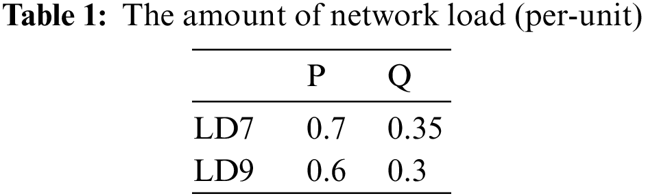
Fig. 1 shows the single-line diagram of the system under study. The system consists of two similar areas connected by a weak connection. Each area consists of two generator units next to each other with rated values of 900 MVA and 20 KV. For each unit, a 900 MVA transformer with 20/230 KV voltage conversion ratio has been used [32]. The values of active and reactive powers LD7 and LD9 are given in Tab. 1.
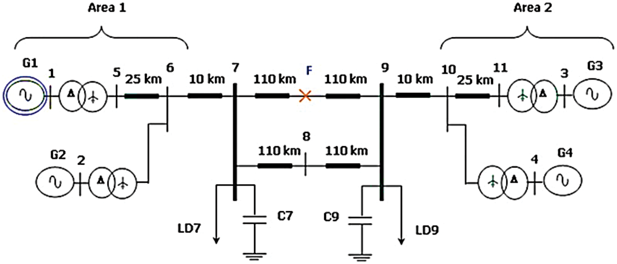
Figure 1: The under study system
It must be mentioned that all generators are equipped with a PSS. The lead-lag PSS is an electronic feedback control from the excitation system of the generation unit; its task is to dampen the oscillations and increase the stability margin of the power system rotor angle by modulating the generator excitation voltage. To provide damping, the stabilizer produces an electrical torque component in phase with rotor speed deviation. Fig. 2 shows the general structure of modeling and performance of the PSS considering the excitation system. Since the PPS must generate in-phase electrical torque with speed variations, the lead-lag block is used in the PSS [33]. The number of lead-lag blocks depends on the nature of the system and how the PSS is adjusted for the required phase variation. The phase compensation block provides the appropriate lead characteristic for lead compensation between the excitation input and the electrical torque of the generator.
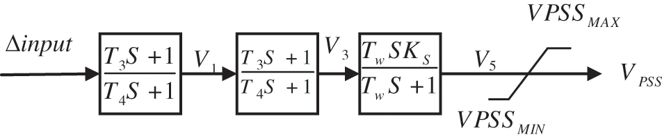
Figure 2: The block diagram of the lead-lag stabilizer
This controller consists of several washout blocks and results in the reduction of responses higher than tolerable limits of the power system in case large distortions occur. Since the PSS must produce in-phase electrical torque with speed variations, the lead-lag block is used in the PSS. The number of lead-lag blocks depends on the nature of the system and how the PSS is adjusted for the required phase variation. The phase compensation block provides the appropriate lead characteristic for compensation between the excitation input and the generator electrical torque. The steady-state effect eliminating block acts as a high-pass filter with a large enough
In simulations, conventional power system stabilizers (CPSS), optimized power system stabilizers (OPSS) also robust design of power system stabilizers (RPSS) optimized by the differential evolution algorithm have been used. To evaluate the performance of the stabilizers in the power system under study, three-phase to ground fault with 200 ms duration at t = 2 s and at the point F specified by a cross in Fig. 1 is applied.
3 The Objective Function and Constraints
In this paper, the following objective function has been used for the robust design of PSSs and producing coordination.
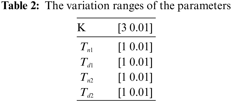
In Eq. (1), N is the number of operating conditions of the system under study, w is the generator angular speed, and t is the time operator. The variation ranges for decision variables are given in Tab. 2 [35]. For the optimum and robust design of PSSs, the differential evolution algorithm has been used.
4 The Differential Evolution Algorithm
Storn and Price first introduced the differential evolution algorithm in 1995. They showed that this algorithm has a good ability for optimizing the non-differentiable non-linear functions. It has been introduced as a powerful and fast method for optimizing problems in continuous spaces. In other algorithms, at first, the crossover operator is applied then the mutation is done. In this algorithm in contrast at first, the mutation is applied then crossover is performed to generate a new population. For applying the mutation operator, no special distribution is used but the mutation step length is equal to the distance among the current members.
The position of members provides valuable information about the space of the value function. For example, when a random initialization method is used for generating the initial population, this population is a good representation of the whole search space that the distance between members is relatively large. By advancing the time and search procedure, the distance between members is reduced until all members converge to a similar solution. It must be remembered that the size of the distance between members is affected by the population size. The higher the number of members in the population, the smaller the length of this distance. The distance between members is a good sign of diversity between the current population also the step size for converging to a point. It means that if the distance between members is large, for the maximum possible exploration of the search space, the members must have a large step size. On the other hand, if distance between members is short, the step size for exploring the local areas must be small. Select a target vector
The smaller the
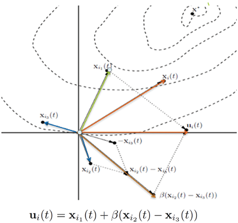
Figure 3: The differential evolution algorithm
Usually, the uniform distribution is used to generate the initial population. The members of the population are distributed uniformly in the space and at each step of the algorithm, they come closer together and this convergence results in approaching the optimum solution. Also, it must be noted that the larger population size could be a proper help to find the optimum solution [36–66].
One of the important factors in this algorithm is determining an appropriate value for the scale coefficient. If it is chosen small, the step size in generating new particle will be smaller and longer time is spent on the search. If the scale coefficient is chosen high for the differential evolution algorithm, the algorithm may skip the proper solutions. After generating a new particle, the mutation is done by generating a random number between 0 and 1. If the generated number is lower than the mutation rate, the desired element in that population member is taken from the mutation part. Otherwise, the element is taken from the initial value of the member. Then, the newly produced matrix is compared with the initial matrix. If the new matrix has a lower cost, it replaces the initial matrix. This is done for all members of the population. Fig. 4 shows the flowchart of the differential evolution algorithm.
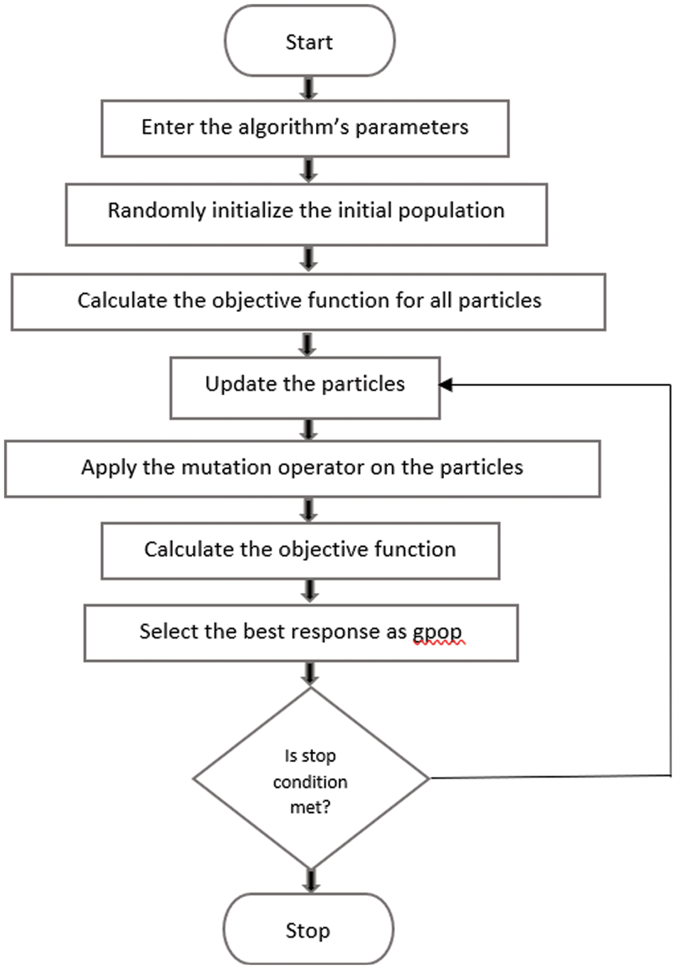
Figure 4: The flowchart of the differential evolution algorithm
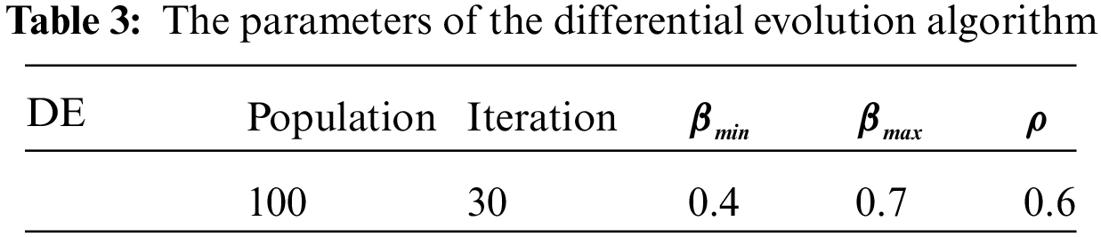
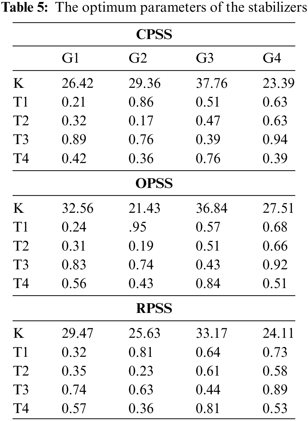
For designing the OPSS and RPSS stabilizers, the differential evolution algorithm has been used. The algorithm’s parameters are given in Tab. 3. The performance of the designed PSS is evaluated at rated load and full load. The values of the generated active and reactive power of the generators in both scenarios are given in Tab. 4 [36]. The values of the parameters after the optimized design of OPSS and RPSS stabilizers with the differential evolution algorithm are presented in Tab. 5.
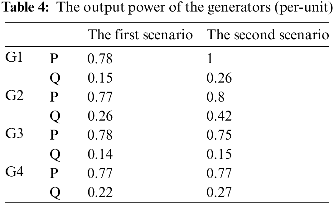
In the first scenario, the output power of the generators is adjusted according to Tab. 4. After installing the OPSS and RPSS stabilizers designed by the PSO and DE algorithms in the generators’ excitation system and applying three-phase to ground fault with 200 ms duration at t = 2 s, studies have been performed. In Fig. 5, the amplitudes of the inter-area mode oscillations are shown as
In Fig. 5, the red dashed line and blue dotted line are corresponding to the power systems that use the OPSS and CPSS, respectively. The black bold line is the inter-area and intra-area mode oscillations in the power system when the stabilizer with designed the RPSS method has been used.
According to the results obtained in Fig. 5, the maximum deviation amplitude of the modes after applying 200 ms fault at t = 2 s is
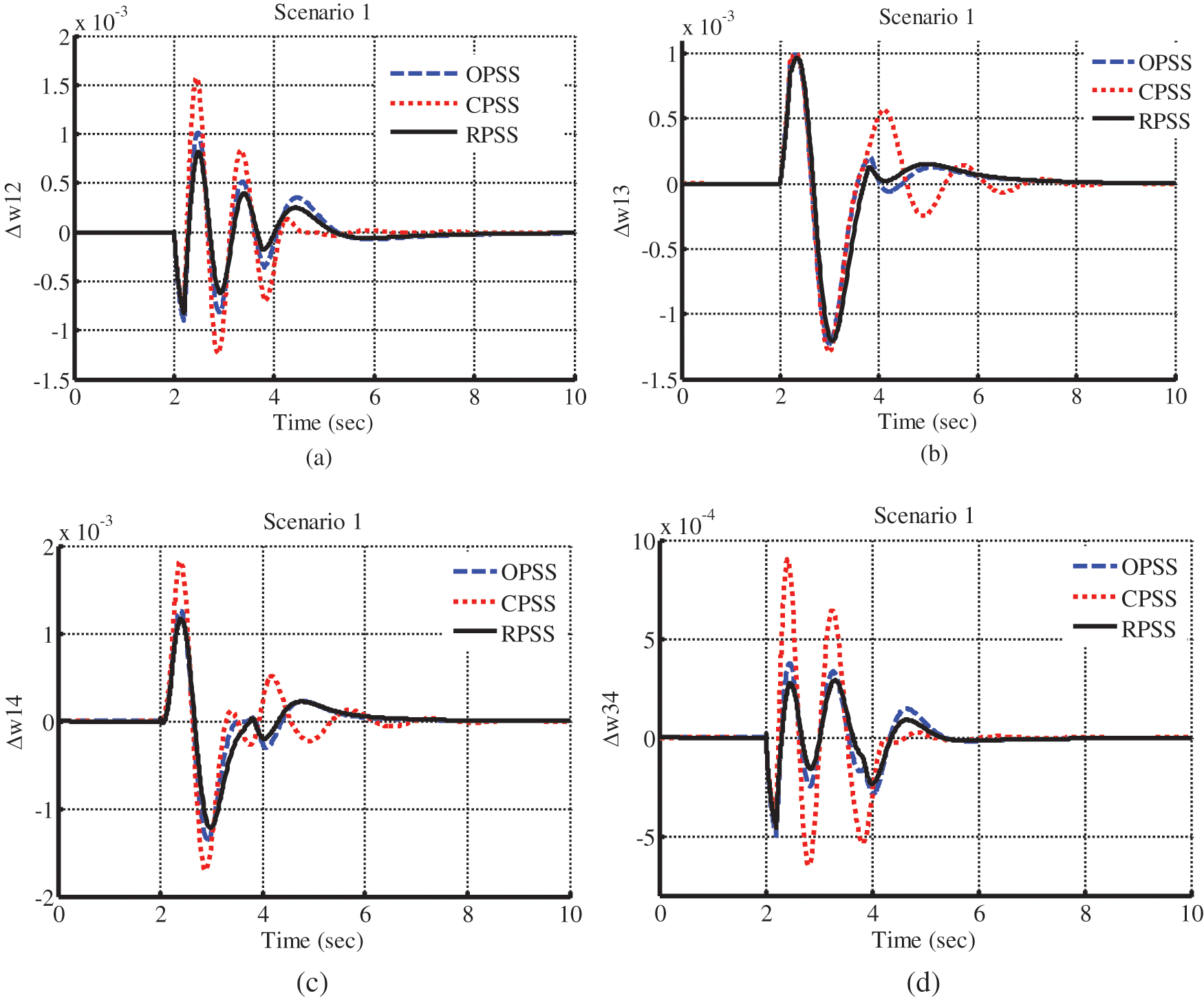
Figure 5: Inter-area and intra-area mode oscillations in the first scenario
On the other hand, whenever the oscillations are damped in a shorter time, the power system will have better dynamic stability conditions and the probability for instability will be lower. As a result, a stabilization method with shorter oscillation damping times is preferred. It must be mentioned that in simulations, the settling time of oscillation is calculated as 4% of the final value. Accordingly, noticing the Fig. 5, the damping time for oscillation modes in the power system with CPSS stabilizers is about 5.47 s while it is 3.44 s for the power system with OPSS stabilizers. However, if the stabilizers are designed as robust PSS, the settling time is reduced and will be equal to 3.18 s that is lower than both other stabilizers.
In the following, for more accurate analysis of the results obtained in the first scenario, indices of the maximum deviation (MD) amplitude percentage, the time required for damping modes’ oscillation (TS), also the value of the objective function for all stabilizer are presented in Tab. 6. It must be mentioned that each of these three indices represents the better performance of that stabilizer in damping the oscillations and improving the dynamic stability margin of the power system.

In other words, the value of the objective function is the integral square time square error (ISTSE) measure for the power system that uses the proposed RPSS stabilizer has a lower value compared to two other similar power systems. The value of the objective for the power system with the RPSS is equal to 0.026. It is equal to 0.054 and 0.032 for the power systems with the CPSS and OPSS, respectively. As stated earlier, the lower value of the objective function indicates a lower amplitude for the oscillations and shorter time for damping which is true for the first scenario. The maximum deviation amplitude and time required for oscillation damping for inter-area and intra-area modes are obtained 0.087 rad/s and 3.18 rad/s, respectively, for the RPSS stabilizers, while these two indices are obtained higher for two other stabilizers. The maximum oscillation amplitude is higher for the conventional stabilizers (CPSS) which results in a higher probability for instability and losing synchronization in case of a more severe fault.
The performance of a stabilizer is verified if it dampens the oscillations acceptably when the operating conditions change. In the second scenario, the studies repeated by increasing the output power of the generators. In the new conditions, three-phase to ground fault with 200 ms duration is also applied to the connection line between two areas. The results are shown in Fig. 6.
Considering Fig. 6, the maximum deviation amplitude of inter-area and intra-area mode oscillation, in the power system with the conventional stabilizers (CPSS) is obtained as
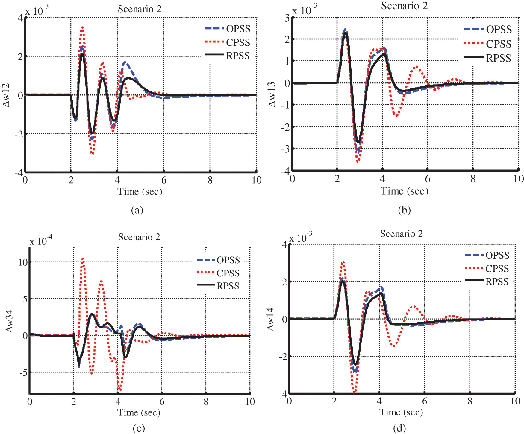
Figure 6: Inter-area and intra-area mode oscillation in the second scenario
On the other hand, the maximum time required for damping the inter-area and intra-area oscillations, if the CPSS is used is equal to 6.29 s and for the OPSS is 4.54 s. The minimum damping time is associated with the RPSS stabilizers with 4.09 s. The shorter damping time caused the system to have stable conditions in the fastest time and not to get unstable in the case of further fault. In the following, Tab. 7 summarizes the values of the indices for all methods of stabilizing the power system in the second scenario.
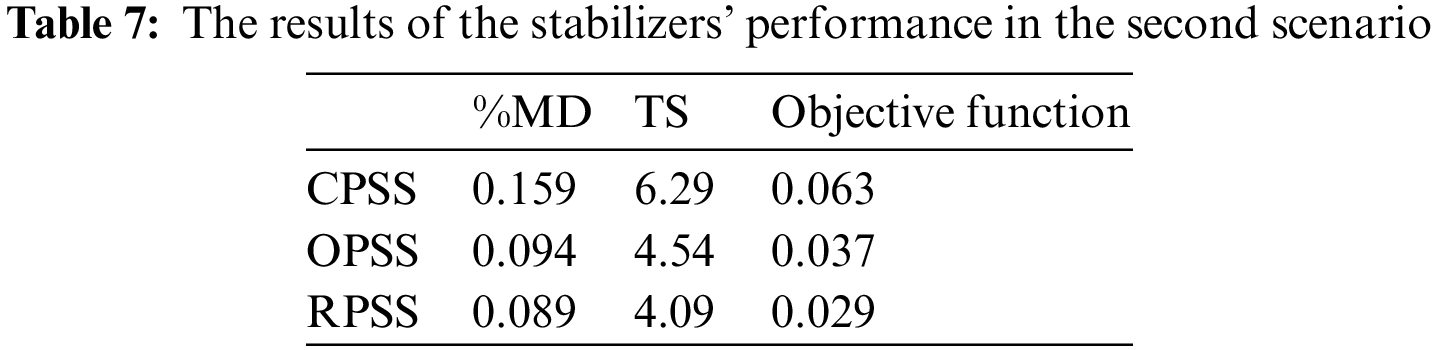
The values of the objective function, if the CPSS and OPPS are used in the power system under study, are calculated as 0.063 and 0.037, respectively, while will be equal to 0.029 if the RPSS stabilizers are utilized. In the second scenario, similar to the first scenario, the power system under study which uses the RPSS stabilizers obtains a lower value of the objective function compared to two other stabilizers and this is verification of this stabilization method. In addition, the maximum deviation amplitude and oscillation damping time in the second scenario is associated with the RPSS.
For evaluating the performance of the designed stabilizers, the loading conditions for the generators are changed again. In the third scenario, loads of the generators are reduced compared to the first scenario and adjusted according to Tab. 4. In addition, in these conditions, a three-phase to ground fault with 200 ms duration is applied to the connection line between two areas. The results are shown in Fig. 7.
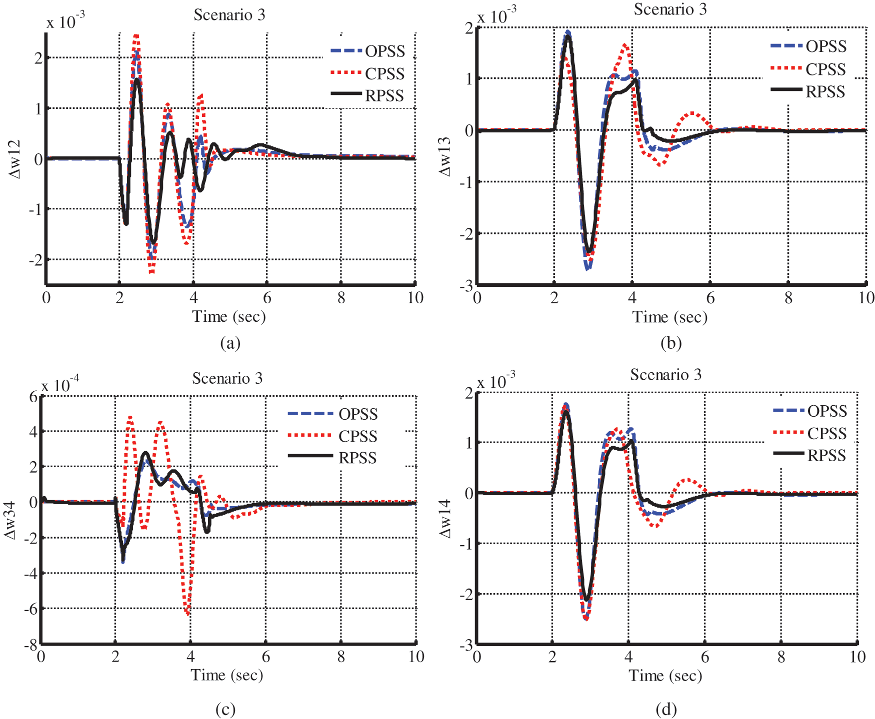
Figure 7: Inter-area and intra-area mode oscillations in the third scenario
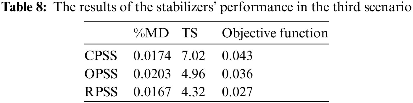
In addition, in the third scenario like two previous scenarios, the values of the maximum deviation amplitude and oscillation damping time indices and the value of the objective function, as a result, are calculated. According to this, the maximum deviation amplitude of the inter-area and intra-area mode oscillations for the power system under study, which uses the CPSS, is about
The maximum time required for damping the inter-area and intra-area mode oscillation in the power system with CPSS is 7.02 s and is approximated as 4.96 s if the OPSS is used. However, the value of this index in presence of the RPSS is equal to 4.32 s, which is lower than two other control methods. In the following, in Tab. 8, the values of the maximum deviation, damping time, and the objective function for all stabilizers are presented for the third scenario. The value of the objective function in the third scenario, if the CPSS and OPSS stabilizers are used, is equal to 0.043 and 0.036, respectively. The value of this index is equal to 0.027 if the RPSS is utilized. The value of the objective function in the power system that uses the RPSS is lower than two other power systems, and it means better performance for this stabilizer in damping the modes’ oscillations.
For evaluating the performance of the designed stabilizers in three defined scenarios, the simulation results are studied numerically. For this purpose, the values of the objective function also the maximum deviation amplitude of the inter-area and intra-area mode oscillations, and damping time are depicted as bar charts associated with each of them. It must be mentioned again that a lower value of these indices indicates a higher stability margin. Fig. 8 shows the values of the objective function for each of the stabilizers and three defined scenarios.
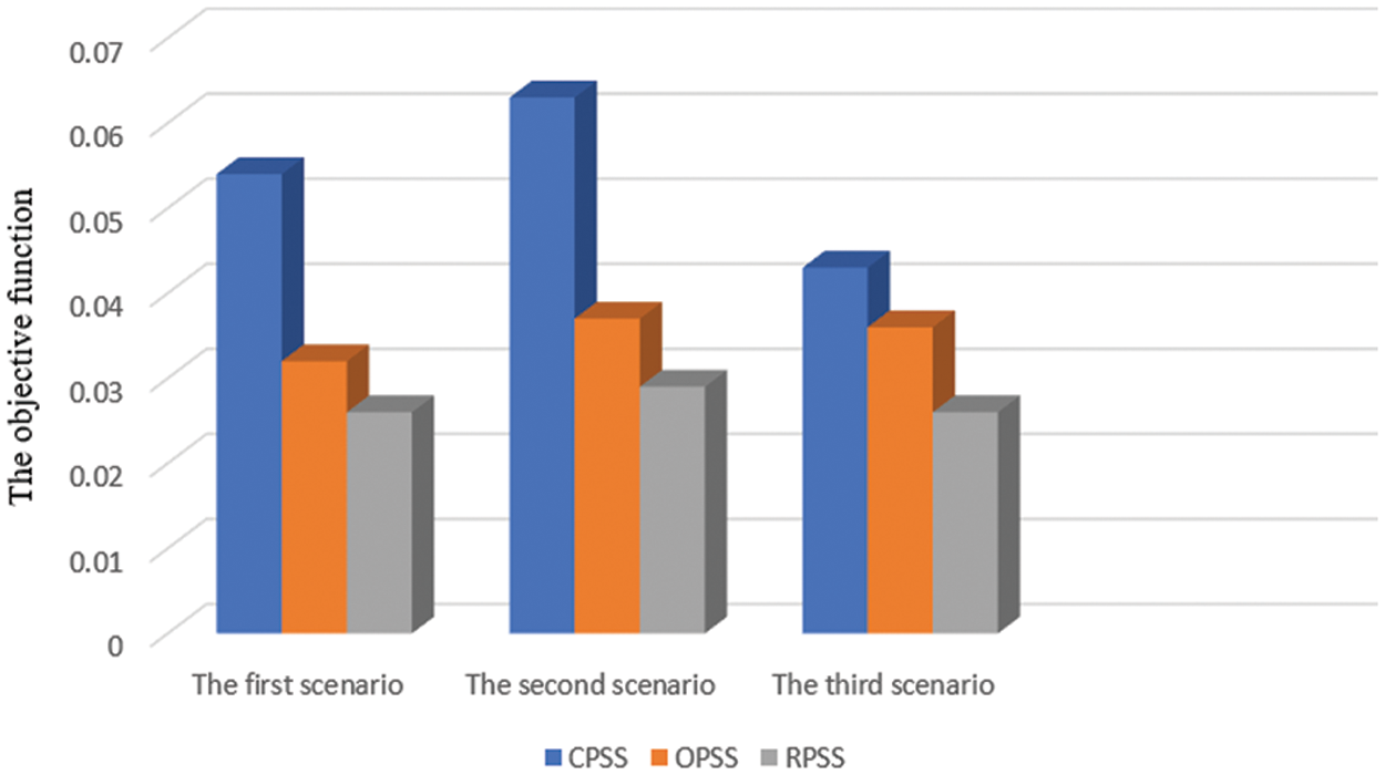
Figure 8: Bar charts of the objective function
In Fig. 8, the bars with red, blue, and green colors are related to the power systems with the CPSS, OPSS, and RPSS stabilizers, respectively. Accordingly, it can be stated that in minimizing the objective function, in all three scenarios, the power system with RPSS designed by the differential evolution algorithm has a lower value than two other stabilizers. The highest difference is obtained in the second scenario where increasing the system load the probability of instability is increased. A lower value of the objective function indicates that the stabilizing system will have the ability to dampen the oscillation in a shorter time with lower amplitude. The values of the objective function in all three scenarios with the proposed RPSS are relatively close. The reason for this is its robust design and considering all operating conditions in designing the stabilizer. Inversely, the highest value of the objective function is associated with the power system with CPSS. This high value means a lower stability margin and a higher probability for instability.
Another appropriate index for comparing the performance of the stabilizers used in simulations is the maximum deviation from the reference inter-area and intra-area mode oscillations. The lower the amplitude of the oscillations, the more dynamically stable the system. Fig. 9 shows the percentage of the maximum deviation of the oscillations in three scenarios as bar charts.
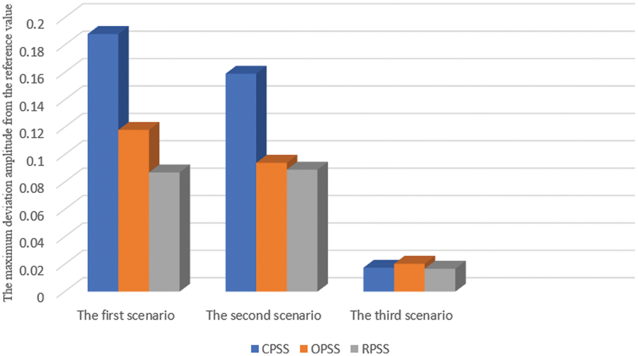
Figure 9: Bar charts of the maximum deviation of the oscillation
In all scenarios, the maximum deviation amplitude associated with the RPSS is lower than two other stabilizers, and this is a verification of the performance of the proposed control system and accurate coordination between the stabilizers. On the other hand, the CPSS has no proper conditions in the first and second scenarios, and the maximum deviation amplitude is very large in this system. It prevents using the maximum capacity of the power system because the appropriate stability margin is low. Another criterion to compare the performance of the stabilizers and determine the superiority of one over the others is the maximum time required for damping the oscillations. As much as the stabilizer could dampen the oscillations resulting from distortions in the power system, it will have better conditions from the performance point of view. In the following, Fig. 10 shows the maximum damping time for three scenarios for each of the stabilizers.
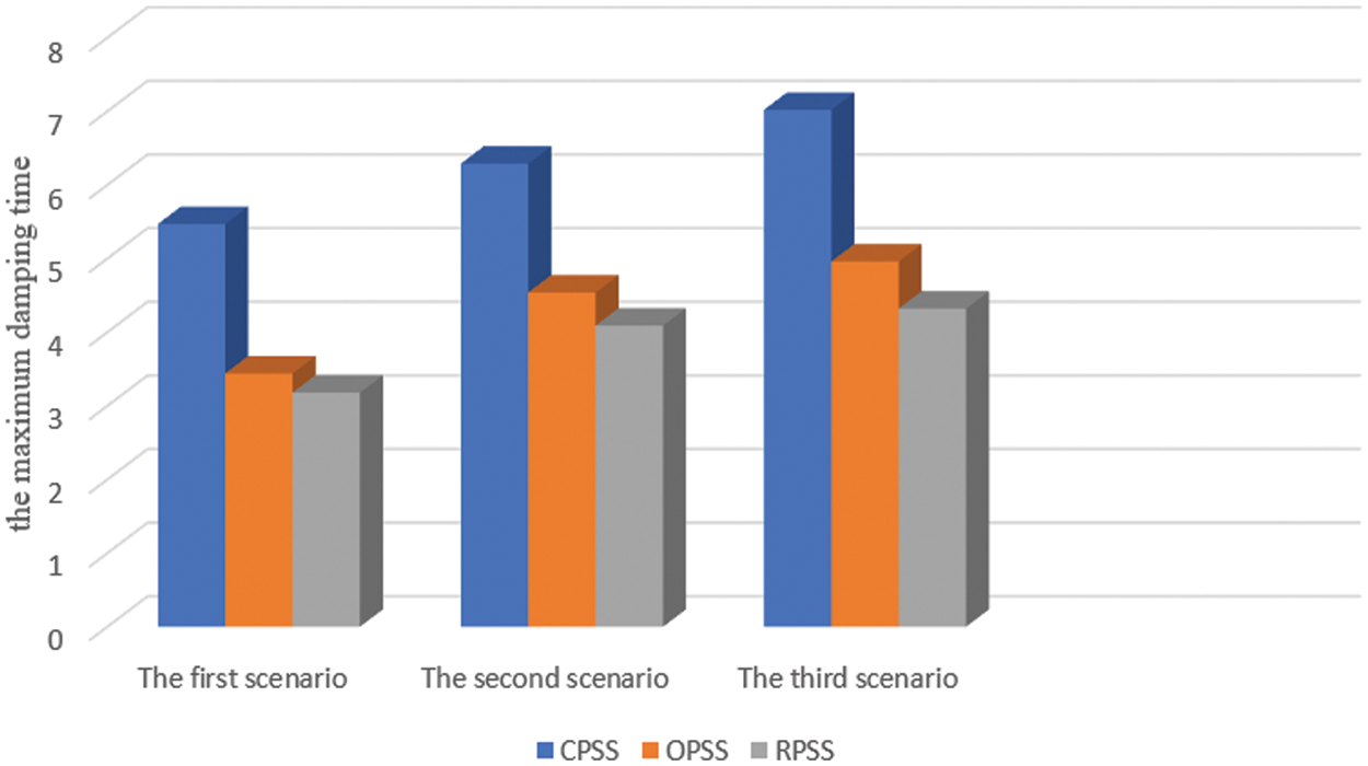
Figure 10: Bar charts for the maximum oscillations’ damping time
Like two previous criteria, the value of this index for the proposed RPSS is lower than two other stabilizers. The damping time, if the operating conditions of the generators change, for the power system with the RPSS is lower than 4.5 s that is relatively a proper condition. On the other hand, the OPSS has a lower settling time compared to the RPSS. It is appropriate to design the stabilizers optimally for better performance. It can be said that the lower the settling time, the more dynamically stable the power system, and by increasing the dynamic stability, the power system will be able to transmit more power with a proper stability margin.
In this paper, a comparison has been performed between the proposed RPSS, which is a lead-lag stabilizer with its parameters determined robustly using the differential evolution algorithm, with the conventional (CPSS) and the optimized (OPSS) stabilizers. For this purpose, a standard four-machine power system has been used for the studies and simulations. Simulations are performed in three different loading conditions as three scenarios by applying a three-phase to ground fault with 200 ms duration in connection line between two areas of the power system under study to evaluate the performance of various stabilizers. For this purpose, the values of the maximum deviation from a reference value, the time required for oscillation damping also the value of the objective function are calculated for three stabilizers in three scenarios. According to the results obtained from the simulations, the values of the objective function in three scenarios for the power system with the RPSS stabilizers designed by the differential evolution algorithm are relatively close to each other and are lower than the objective function of two other controllers. A lower value of the objective function implies that the system can dampen the oscillations in a shorter time with lower amplitude. The reason for this is the robust design of the RPSS stabilizer and considering different operating conditions for the design procedure. However, the maximum value of the objective function is obtained for the convention stabilizers (CPSS). A high value of this index means a higher probability for instability. One other index calculated to compare the performance of the stabilizers in simulations is the maximum deviation from the reference oscillations in oscillation modes in the power system. The lower the oscillations amplitude, the more dynamically stable the system, and there is the possibility to transmit more electric energy for connection line between two areas with a proper stability margin. In all three scenarios, the maximum deviation amplitude of the oscillation modes in the power system with the proposed RPSS is lower than two other methods, and this is a verification of the correct performance of the proposed control system. Unlike the RPSS, the conventional stabilizer (CPPS) does not have an appropriate condition in the first and second scenarios, and the deviation amplitude of oscillation mode is large. This issue, because of a lower stability margin, prevents using the maximum capacity of the transmission lines. Another criterion considered in the studies is the maximum time needed for damping the inter-area and intra-area mode oscillations in the power system under study. As much as the stabilizer could dampen the oscillation modes in a shorter time, it will have better performance and the probability of instability will be lower. Shorter damping time causes the system to get stable in the fastest time and not to become unstable in case of additional faults. Simulation results show that in all three scenarios, the damping time for the proposed RPSS is lower than two other stabilizers. The damping time for different loading conditions of the generators in the power system with the RPSS stabilizers is calculated to be less than 4.5 s. On the other hand, the oscillations’ damping time in the power system with the OPSS has a lower value in comparison to the conventional RPSS. So, it is recommended to design the stabilizers optimally for better performance.
Funding Statement: The authors received no specific funding for this study.
Conflicts of Interest: The authors declare that they have no conflicts of interest to report regarding the present study.
1. V. Keumarsi, M. Simab and G. Shahgholian, “An integrated approach for optimal placement and tuning of power system stabilizer in multi-machine systems,” International Journal of Electrical Power & Energy Systems, vol. 63, pp. 132–139, 2014. [Google Scholar]
2. O. Zeyed, L. Cipcigan and T. Muhssin, “Power system oscillations and control: Cassifications and PSSs’ design methods: A review,” Renewable and Sustainable Energy Reviews, vol. 79, pp. 839–849, 2017. [Google Scholar]
3. M. Derafshian and N. Amjadi, “Optimal design of power system stabilizer for power systems including doubly fed induction generator wind turbines,” Energy, vol. 84, pp. 1–14, 2015. [Google Scholar]
4. R. Hemmati, “Power system stabilizer design based on optimal model reference adaptive system,” Ain Shams Engineering Journal, vol. 89, pp. 63766–67178, 2016. [Google Scholar]
5. A. Hashman and I. Erlich, “Mode selective damping of power system electromechanical oscillations for large power systems using supplementary remote signals,” Automatisierungstechnik, vol. 59, no. 3, pp. 145–152, 2011. [Google Scholar]
6. H. Shayeghi and A. Ghasemi, “A multi objective vector evaluated improved honey bee mating optimization for optimal and robust design of power system stabilizers,” International Journal of Electrical Power & Energy Systems, vol. 62, pp. 630–645, 2014. [Google Scholar]
7. P. Kundur, Power System Stability and Control, New York: McGraw-Hill, 1994. [Google Scholar]
8. “IEEE TF report. proposed terms and definitions for power system stability,” IEEE Transactions on Power Apparatus and Systems, vol. PAS-101, no. 7, pp. 1894–1897, 1982. [Google Scholar]
9. P. Kundur, J. Paserba, V. Ajjarapu, G. Andersson, A. Bose et al., “Definition and classification of power system stability: IEEE/CIGRE joint task force on stability terms and definitions,” IEEE Transactions on Power System,; vol. 19, pp. 1387–1401, 2004. [Google Scholar]
10. G. Gurrala and I. Sen, “Power system stabilizers design for interconnected power systems,” IEEE Transactions on Power System, vol. 25, pp. 1042–1051, 2010. [Google Scholar]
11. H. Huerta, A. Loukianov and J. Canedo, “Robust multi-machine power systems control via high order sliding modes,” Electric Power Systems Research, vol. 81, no. 7, pp. 1602–1609, 2011. [Google Scholar]
12. H. Natke and Y. Ben-Haim, “Uncertainty: A discussion from various points of view,” in Uncertainty: Models and Measures, Berlin, Germany: Akademie Verlag, 1996. [Google Scholar]
13. M. Asselt and J. Rotmans, “Uncertainty in integrated assessment modelling - from positivism to pluralism,” Journal of Climatic Change, vol. 54, pp. 75–105, 2002. [Google Scholar]
14. G. J. Klir, “Principles of uncertainty: What are they? Why do we need them?,” Fuzzy Sets and Systems, vol. 74, no. 1, pp. 15–31, 1995. [Google Scholar]
15. Y. Li, J. Chen and L. Feng, “Dealing with uncertainty: A survey of theories and practices knowledge and data engineering,” IEEE Transactions on Knowledge and Data Engineering, vol. 25, no. 11, pp. 2463–2482, 2013. [Google Scholar]
16. K. Durga Rao, V. Gopika, V. V. S. Sanyasi Rao, H. S. Kushwaha, A. K. Verma et al., “Dynamic fault tree analysis using monte carlo simulation in probabilistic safety assessment,” Reliability Engineering and System Safety, vol. 94, no. 4, pp. 872–883, 2009. [Google Scholar]
17. M. A.Kamarposhti, H. Shokouhandeh, I. Colak, S. S. Band and K. Eguchi, “Optimal location of FACTS devices in order to simultaneously improving transmission losses and stability margin using artificial bee colony algorithm,” in IEEE Access, vol. 9, pp. 125920–125929, 2021. [Google Scholar]
18. L. H. Hassan, M. Moghavvemi, H. A. F.Almurib, K. M. Muttaqi and V. G. Ganapathy, “Optimization of power system stabilizers using participation factor and genetic algorithm,” International Journal of Electrical Power & Energy Systems, vol. 55, no. 2, pp. 668–79, 2014. [Google Scholar]
19. H. Mostafa, M. EI-Sharkawy, A. Emary and K. Yassin, “Design and allocation of power system stabilizers using the particle swarm optimization technique for an inter connected power system,” International Journal of Electrical Power & Energy Systems, vol. 34, no. 1, pp. 57–65, 2012. [Google Scholar]
20. S. Panda, N. K. Yegireddy and S. K. Mohapatra, “Hybrid BFOA–PSO approach for coordinated design of PSS and SSSC-based controller considering time delays,” International Journal of Electrical Power & Energy Systems, vol. 49, no. 1, pp. 221–233, 2013. [Google Scholar]
21. S. M. Abd-Elazim and E. S. Ali, “A hybrid particle swarm optimization and bacterial foraging for optimal power system stabilizer design,” International Journal of Electrical Power & Energy Systems, vol. 46, pp. 334–341, 2013. [Google Scholar]
22. M. R. Esmaili, R. A. Hooshmand, M. Parastegari, P. Ghaebi Panah and S. Azizkhani, “New coordinated design of SVC and PSS for multi-machine power system using BF-PSO algorithm,” Procedia Technology, vol. 11, pp. 65–74, 2013. [Google Scholar]
23. S. M. Abd-Elazim and E. S. Ali, “Coordinated design of PSSs and SVC via bacterial foraging optimization algorithm in a multi-machine power system,” International Journal of Electrical Power & Energy Systems, vol. 41, no. 1, pp. 44–53, 2013. [Google Scholar]
24. S. Abd-Elazim and E. Ali, “Power system stability enhancement via bacteria foraging optimization algorithm,” Arabian Journal for Science and Engineering, vol. 38, no. 3, pp. 599–611, 2013. [Google Scholar]
25. M. Tripathy and S. Mishra, “Coordinated tuning of PSS and TCSC to improve hopf bifurcation margin in multi machine power system by a modified bacteria foraging algorithm,” Electrical Power and Energy Systems, vol. 66, pp. 97–109, 2015. [Google Scholar]
26. D. K. Sambariya and R. Prasad, “Robust tuning of power system stabilizer for small signal stability enhancement using meta heuristic bat algorithm,” International Journal of Electrical Power & Energy Systems, vol. 61, pp. 229–38, 2014. [Google Scholar]
27. E. S. Ali, “Optimization of power system stabilizers using BAT search algorithm,” International Journal of Electrical Power & Energy Systems, vol. 61, pp. 683–690, 2014. [Google Scholar]
28. M. Eslami, H. Shareef and M. Khajehzadeh, “Optimal design of damping controllers using a new hybrid artificial bee colony algorithm,” International Journal of Electrical Power & Energy Systems, vol. 52, pp. 42–54, 2013. [Google Scholar]
29. E. Gholipour and M. Nosratabadi, “A new coordination strategy of SSSC and PSS controllers in power system using SOA algorithm based on pareto method,” International Journal of Electrical Power & Energy Systems, vol. 67, pp. 462–471, 2015. [Google Scholar]
30. R. Jalayer and B. Ooi, “Co-ordinated PSS tuning of large power systems by combining transfer function-eigen function analysis (TFEAoptimization, and eigenvalue sensitivity,” IEEE Transaction on Power System, vol. 29, no. 6, pp. 2672–2680, 2014. [Google Scholar]
31. R. Khadanga and J. Satapathy, “Time delay approach for PSS and SSSC based coordinated controller design using hybrid PSO–GSA algorithm,” Electrical Power & Energy Systems, vol. 71, pp. 262–273, 2015. [Google Scholar]
32. B. Mehta, P. Bhatt and V.Pandya, “Small signal stability analysis of power systems with DFIG based wind power penetration,” Electrical Power and Energy Systems, vol. 58, pp. 64–74, 2014. [Google Scholar]
33. R. Khezri and H. Bevrani, “Voltage performance enhancement of DFIG-based wind farms integrated in large-scale power systems: Coordinated AVR and PSS,” Electrical Power and Energy Systems, vol. 73, pp. 400–411, 2015. [Google Scholar]
34. P. Padhy, S. C. Srivastava and N. K. Verma, “Robust wide-area TS fuzzy output feedback controller for enhancement of stability in multimachine power system,” IEEE Systems Journal, vol. 6, no. 3, pp. 426–435, 2012. [Google Scholar]
35. M. Ouassaid, M. Maarou and M. Cherkaoui, “Observer-based nonlinear control of power system using sliding mode control strategy,” Electric Power Systems Research, vol. 84, no. 1, pp. 135–143, 2012. [Google Scholar]
36. M. Mahmud, M. Hossain and H. Pota, “Transient stability enhancement of multimachine power systems using nonlinear observer-based excitation controller,” International Journal of Electrical Power & Energy Systems, vol. 58, pp. 57–63, 2014. [Google Scholar]
37. B. Cao, J. Zhao, X. Liu, J. Arabas, M. Tanveer et al., “Multiobjective evolution of the explainable fuzzy rough neural network with gene expression programming,” IEEE Transactions on Fuzzy Systems (Early Access), vol. X, pp. 1–10, 2022. [Google Scholar]
38. Y. He, L. Dai and H. Zhang, “Multi-branch deep residual learning for clustering and beamforming in user-centric network,” IEEE Communications Letters, vol. 24, no. 10, pp. 2221–2225, 2020. [Google Scholar]
39. Y. Zhang, F. Liu, Z. Fang, B. Yuan, G. Zhang et al., “Learning from a complementary-label source domain: Theory and algorithms,” IEEE Transaction on Neural Networks and Learning Systems, vol. X, pp. 1–15, 2021. [Google Scholar]
40. L. Zhong, Z. Fang, F. Liu, B. Yuan, G. Zhang et al., “Bridging the theoretical bound and deep algorithms for open set domain adaptation,” IEEE Transaction on Neural Networks and Learning Systems, vol. X, pp. 1–15, 2021. [Google Scholar]
41. L. Zhang, T. Gao, G. Cai and K. L. Hai, “Research on electric vehicle charging safety warning model based on back propagation neural network optimized by improved gray wolf algorithm,” Journal of Energy Storage, vol. 49, pp. 104092, 2022. [Google Scholar]
42. L. Zhang, X. Wang, Z. Zhang, Y. Cui, L. Ling et al., “An adaptive control strategy for interfacing converter of hybrid microgrid based on improved virtual synchronous generator,” IET Renewable Power Generation, vol. 16, no. 2, pp. 261–273, 2021. [Google Scholar]
43. W. Yang, X. Chen, Z. Xiong, Z. Xu, G. Liu et al., “A privacy-preserving aggregation scheme based on negative survey for vehicle fuel consumption data,” Information Sciences, vol. 570, pp. 526–544, 2021. [Google Scholar]
44. B. Li, Y. Feng, Z. Xiong, W. Yang and G. Liu, “Research on AI security enhanced encryption algorithm of autonomous IoT systems,” Information Sciences, vol. 575, pp. 379–398, 2021. [Google Scholar]
45. G. Sun, C. Li and L. Deng, “An adaptive regeneration framework based on search space adjustment for differential evolution,” Neural Computing and Applications, vol. 33, pp. 9503–9513, 2021. [Google Scholar]
46. S. Fan, Y. Wang, S. Cao, B. Zhao, T. Sun et al., “A deep residual neural network identification method for uneven dust accumulation on photovoltaic (PV) panels,” Energy, vol. 239, pp. 122302, 2022. [Google Scholar]
47. T. Cai, M. Dong, H. Liu and S. Nojavan, “Integration of hydrogen storage system and wind generation in power systems under demand response program: A novel P-robust stochastic programming,” International Journal of Hydrogen Energy, vol. 47, no. 1, pp. 443–458, 2021. [Google Scholar]
48. Y. Peng, Z. Xu, M. Wang, Z. Li, J. Peng et al., “Investigation of frequency-up conversion effect on the performance improvement of stack-based piezoelectric generators,” Renewable Energy, vol. 172, pp. 551–563, 2021. [Google Scholar]
49. B. Bai, R. Zhou, G. Cai, W. Hu and G. Yang, “Coupled thermo-hydro-mechanical mechanism in view of the soil particle rearrangement of granular thermodynamics,” Computers and Geotechnics, vol. 137, pp. 104272, 2021. [Google Scholar]
50. F. Meng, S. Yang, J. Wang, L. Xia and H. Liu, “Creating knowledge graph of electric power equipment faults based on BERT–BiLSTM–CRF model,” Journal of Electrical Engineering & Technology, vol. 53, pp. 1–10, 2022. [Google Scholar]
51. Z. Chen, J. Tang, X. Y. Zhang, D. K. C. So, S. Jin et al., “Hybrid evolutionary-based sparse channel estimation for IRS-assisted MM wave MIMO systems,” IEEE Transactions on Wireless Communications, vol. 21, no. 3, pp. 1586–1601, 2022. [Google Scholar]
52. X. Jin, Y. Chen, L. Wang, H. Han and P. Chen, “Failure prediction, monitoring and diagnosis methods for slewing bearings of large-scale wind turbine: A review,” Measurement: Journal of the International Measurement Confederation, vol. 172, no. 5, pp. 108855, 2021. [Google Scholar]
53. T. Wang, W. Liu, J. Zhao, X. Guo and V. Terzija, “A rough set-based bio-inspired fault diagnosis method for electrical substations,” International Journal of Electrical Power & Energy Systems, vol. 119, pp. 105961, 2020. [Google Scholar]
54. T. Wang, X. Wei, J. Wang, T. Huang, H. Peng et al., “A weighted corrective fuzzy reasoning spiking neural P system for fault diagnosis in power systems with variable topologies,” Engineering Applications of Artificial Intelligence, vol. 92, pp. 103680, 2020. [Google Scholar]
55. G. Xiao, B. Chen, S. Li and X. Zhuo, “Fatigue life analysis of aero-engine blades for abrasive belt grinding considering residual stress,” Engineering Failure Analysis, vol. 131, pp. 105846, 2022. [Google Scholar]
56. S. Chen, J. Zhang, F. Meng, D. Wang, Z. Wei et al., “A markov chain position prediction model based on multidimensional correction,” Complexity (New York, N.Y.), vol. 2021, pp. 1–8, 2021. [Google Scholar]
57. F. Meng, A. Pang, X. Dong, C. Han, X. Sha et al., “H∞ optimal performance design of an unstable plant under bode integral constraint,” Complexity (New York, N.Y.), vol. 20,.no. 18, pp. 1–10, 2018. [Google Scholar]
58. F. Meng, D. Wang, P. Yang, G. Xie, R. Cutberto et al., “Application of sum of squares method in nonlinear H∞ control for satellite attitude maneuvers,” Complexity (New York, N.Y.), vol. 2019, pp. 1–10, 2019. [Google Scholar]
59. W. Zheng, X. Liu and L. Yin, “Research on image classification method based on improved multi-scale relational network,” PeerJ Computer Science, vol. 7, pp. 1–21, 2021. [Google Scholar]
60. Z. Ma, W. Zheng, X. Chen and L. Yin, “Joint embedding VQA model based on dynamic word vector,” PeerJ Computer Science, vol. 7, pp. 1–20, 2021. [Google Scholar]
61. W. Zheng, L. Yin, X. Chen, Z. Ma, S. Liu et al., “Knowledge base graph embedding module design for visual question answering model,” Pattern Recognition, vol. 120, pp. 108153, 2021. [Google Scholar]
62. L. Guo, C. Ye, Y. Ding and P. Wang, “Allocation of centrally switched fault current limiters enabled by 5G in transmission system,” IEEE Transactions on Power Delivery, vol. 36, no. 5, pp. 3231–3241, 2021. [Google Scholar]
63. C. Guo, C. Ye, Y. Ding and P. Wang, “A multi-state model for transmission system resilience enhancement against short-circuit faults caused by extreme weather events,” IEEE Transactions on Power Delivery, vol. 36, no. 4, pp. 2374–2385, 2021. [Google Scholar]
64. M. M. Khalaf, “Algorithms and optimal choice for power plants based on m-polar fuzzy soft set decision making criterions,” Acta Electronica Malaysia, vol. 4, no. 1, pp. 11–23, 2020. [Google Scholar]
65. X. R. Zhang, W. F. Zhang, W. Sun, X. M. Sun and S. K. Jha, “A robust 3-D medical watermarking based on wavelet transform for data protection,” Computer Systems Science & Engineering, vol. 41, no. 3, pp. 1043–1056, 2022. [Google Scholar]
66. X. R. Zhang, X. Sun, X. M. Sun, W. Sun and S. K. Jha, “Robust reversible audio watermarking scheme for telemedicine and privacy protection,” Computers, Materials & Continua, vol. 71, no. 2, pp. 3035–3050, 2022. [Google Scholar]
 | This work is licensed under a Creative Commons Attribution 4.0 International License, which permits unrestricted use, distribution, and reproduction in any medium, provided the original work is properly cited. |