DOI:10.32604/cmc.2022.030733
| Computers, Materials & Continua DOI:10.32604/cmc.2022.030733 | |
| Article |
Evaluation of On-Line MPPT Algorithms for PV-Based Battery Storage Systems
1Electrical Engineering Department, College of Engineering, Najran University, Najran, 11001, Saudi Arabia
2Mechanical Engineering Department, College of Engineering-Rabigh, King Abdulaziz University, Jeddah, Saudi Arabia
3K. A. CARE Energy Research and Innovation Center, King Abdulaziz University, Jeddah, 21589, Saudi Arabia
4Center of Excellence in Desalination Technology, King Abdulaziz University, Jeddah, Saudi Arabia
5Department of Electrical and Electronics Engineering, Chaitanya Bharathi Institute of Technology, Hyderabad, 500075, India
6Electrical Power and Machines Department, Faculty of Engineering, Zagazig University, Zagazig, 44519, Egypt
7Electrical Engineering Department, Faculty of Engineering, King Abdul-Aziz University, Jeddah, 80204, Saudi Arabia
*Corresponding Author: Mohamed A. Enany. Emails: m_enany79@yahoo.com, menany@zu.edu.eg
Received: 31 March 2022; Accepted: 10 May 2022
Abstract: This paper presents a novel Simulink models with an evaluation study of more widely used On-Line Maximum Power Point tracking (MPPT) techniques for Photo-Voltaic based Battery Storage Systems (PV-BSS). To have a full comparative study in terms of the dynamic response, battery state of charge (SOC), and oscillations around the Maximum Power Point (MPP) of the PV-BSS to variations in climate conditions, these techniques are simulated in Matlab/Simulink. The introduced methodologies are classified into two types; the first type is conventional hill-climbing techniques which are based on instantaneous PV data measurements such as Perturb & Observe and Incremental Conductance techniques. The second type is a novel proposed methodology is based on using solar irradiance and cell temperature measurements with pre- build Adaptive Neuro-Fuzzy Inference System (ANFIS) model to predict DC–DC converter optimum duty cycle to track MPP. Then evaluation study is introduced for conventional and proposed On-Line MPPT techniques. This comparative study can be useful in specifying the appropriateness of the MPPT techniques for PV-BSS. Also the introduced model can be used as a valued reference model for future research related to Soft Computing (SC) MPPT techniques. A significant improvement of SOC is achieved by the proposed model and methodology with high accuracy and lower oscillations.
Keywords: Photo-voltaic based battery storage systems; adaptive neuro-fuzzy inference system; maximum power point tracking; perturb & observe technique; incremental conductance technique; state of charge
Nomenclature
| Voltage of PV generator, in Volt. | |
| Current of PV generator, in Ampere. | |
| Output power of PV generator output power, in Watt. | |
| Cell insolation photo current, in Ampere. | |
| PV generator insolation photo current, in Ampere. | |
| Cell reverse saturation current, in Ampere. | |
| Reverse saturation current of PV generator, in Ampere. | |
| Series resistance per cell, in Ohm. | |
| Shunt resistance per cell, in Ohm. | |
| Series resistance of PV generator, in Ohm. | |
| Numbers of series- connected solar cells | |
| Number of parallel-connected solar cells | |
| Electron charge, 1.602 × 10⁻¹⁹ C | |
| Boltzmann constant, 1.38 × 10⁻²³ J/k | |
| Cell working temperature in, °C | |
| Completion factor. | |
| PV cell constant in, (1/V) | |
| PV generator constant in, (1/V) | |
| Solar insolation (radiation) level in W/m2. | |
| Maximum output power of PV module, in Watt | |
| Maximum current of PV module, in Ampere. | |
| Maximum voltage of PV module, in Volt. | |
| Short circuit current of PV module, in Ampere | |
| Open circuit voltage of PV module, in Volt | |
| Temperature coefficient of | |
| Temperature coefficient of | |
| OCV | Battery open circuit voltage, in Volt |
| R1 | Battery parallel RC resistance, in Ohm |
| C1 | Battery parallel RC capacitor, in Farad |
| R0 | Battery internal resistance, in Ohm |
| Battery parallel RC voltage, in Volt | |
| Battery voltage, in Volt | |
| Battery current, in Ampere | |
| Dopt | Optimum duty cycle of DC-DC Converter |
| a | Current ratio of DC-DC Converter |
| Sampling period in Sec |
By the end of 2020, the renewable generation power capacity of worldwide has been increased by 261 GW, which is 10.3% higher than 2019’s. 64% Share of new renewable capacity installed in Asia. Solar energy continued to drive capacity expansion with an increase of 127 GW, which represents 22% as shown in Fig. 1 [1]. Solar PV alone accounts for more than 50% of all renewable power expansion [1]. Despite the expansion in PV systems, there are technical constraints due to continuous and sudden changes in climate conditions, so auxiliary systems are required to achieve good energy management. Energy storage technologies are the main key elements that can deal with these constraints [2,3]. There are many Forms of Energy Storage Systems (ESSs) including mechanical, electrochemical, chemical, and thermal energy storage.

Figure 1: Renewable power capacity growth 2016–2020
A Battery storage system is the most activity in 2020 as shown in Fig. 2 due to easy deployment and reduction in cost [2].

Figure 2: Share of global energy storage installed capacity, by technology, 2019 and 2020
Besides, batteries ESS can be designed and produced for any rating, based on voltage and current availability [3], so it represents the second largest ESS technology by the capacity of 14.2 GW (7.5% of total operating storage capacity) [4].
There are 3 main types of conventional Batteries ESS include Lithium-Ion (Li-ion) batteries (92%), Sodium-sulphur (NaS) batteries (3.6%), and Lead-Acid (PpA) batteries (3.4%) [5].
Although Lead-Acid (PpA) batteries are simple to manufacture, easy to recycle, and capable of high discharge currents, besides have high efficiency (70%–80%), long calendar life (5–15 years), high specific power, and low cost per watt-hour, but they are limited using due to poor weight-to-energy ratio, slow charging (14–16 h) and its environmental risk (Pb is a poisonous metal) [6,7]
Also, Sodium-sulphur (NaS) batteries are of limited use because they must be operated at high temperatures (between 300°C and 350°C) which makes their operation dangerous and high costs [8,9].
Where Lithium-Ion (Li-ion) batteries, are the most extensively used technology in electrochemical ESS [10], due to their high energy density, high efficiency, fast charge/discharge, and attractive self-discharge rate (5% per month) [11].
After using Battery ESS, PV systems still suffer from nonlinear behavior or maximum power point variation with the climatic conditions, besides low conversion efficiency which is less than 17%. So, it becomes necessary to use the MPPT system to ensure more efficient energy management operation of PV-based Battery Storage Systems [12,13]. The main target of the MPPT is to reach the PV operating voltage close to the MPP under different climatic conditions. It has become the main component in PV power systems. There are many MPPT techniques that can be classified into three main types;
1) Offline methods or Model-based methods, which are based on the parameters of the PV panel to generate the control signals, such as Computational methods (OCV method and SCC method) [14,15], and Soft Computing based methods (ANFIS based method and FLC based method) [16–19]. The first method is not suitable for fast changes in climate conditions and the second mainly depends on trial and error with prior training which can be time-consuming [20].
2) On-line methods or Model-free methods or hill climbing techniques (Perturb and Observe (P&O) and Incremental Conductance (IncCond)) which are based on instantaneous measurements of PV data. Despite climate conditions changes being rapidly detected, oscillations around the MPP are found [12,13].
3) The Hybrid methods which are based on two algorithms, first an offline method to get the initial operating point close to the MPP of PV, and the second online method to track the MPP faster but with more complexity and cost [20].
Due to cost, ease of implementation, faster dynamic response, model-free method and efficiency, online methods are more suitable for ESS although they suffer from oscillations around the MPP, which it's not an essential point to ESS.
This paper presents an evaluation study of conventional and novel SC online MPPT techniques for PV-BSS which can predict and track the MPP under rapidly changing environmental conditions in a short time with minimum error and low oscillations. Besides, a valued reference model is also introduced to be able to properly simulate the PV-BSS and study the different effects conditions on the battery SOC.
2 Mathematical Model of PV-BSS
The proposed PV-BSS introduced in this work mainly consists of a PV module, a DC-DC converter, and a Li-ion battery as shown in Fig. 3. Steady-state mathematical models for proposed PV-BSS and each component are introduced;

Figure 3: The Schematic diagram of the proposed system
The PV array has nonlinear voltage current characteristic that depends on solar radiation, cell temperature and cells connected pattern as shown below [21,22];
The electrical specification (at STC) of Siemens’s SM55 PV solar module given by manufacturer and mentioned in Appendix can be used to find the five unknown parameters; reverse saturation current per cell Io, radiation photo current per cell Iph, completion factor A, Series resistance per cell Rs and shunt resistance per cell Rsh as follows [23]:
According to the short circuit conditions;
According to the open circuit conditions;
According to the Maximum power conditions;
According to the derivative of PV module current at MPP;
According to the derivative of PV module current at SC;
By solving Eqs. (2) to (6) using a non-linear equation solver as shown in [24], so the electrical parameters of the PV array are known, the simulation model is built in Matlab/Simulink as shown in Fig. 4, and performance curves at different solar radiation and working temperature can be easily shown in Fig.5, but after taking into consideration the parameters that affected by different solar radiation and working temperature as following [25,26];

Figure 4: The simulation model of SM55 PV module at different solar radiation and working temperature

Figure 5: Power-Voltage characteristics of SM55 PV module at different solar radiation and working temperature
The comparison between the simulation results with the specification data given by the manufacturer as shown in Tab. 1 proves that the validity of the proposed simulation model

Due to high sensitivity to changes in duty cycle D, a Boost converter is used. Ideally, (with negligible losses), the output voltage (battery voltage) to input voltage (PV voltage) ratio a in terms of duty cycle is given as follow [16];
So the duty cycle D can be calculated as follows;
There are many equivalent circuit models for lithium-ion batteries. The one-time constant model (OTC) can illustrate the dynamic characteristics of the battery so it is suitable to determine the state of charge (SOC) of the battery.
The OTC model mainly consists of three items including the voltage source VOC, internal resistance Ro, and parallel RC sub circuit (R1 and C1) as shown in Fig. 6. The description of model operation is shown in the discrete time model which can be expressed by the below equations [27,28]:

Figure 6: Battery OTC model equivalent circuit
By using the above two equations besides the parameters of the Li-ion battery cell mentioned in the Appendix; the simulation model is built in Matlab/Simulink as shown in Fig. 7 and the battery voltage and the SOC are shown in Fig. 8.

Figure 7: The simulation model of Lithium-Ion battery
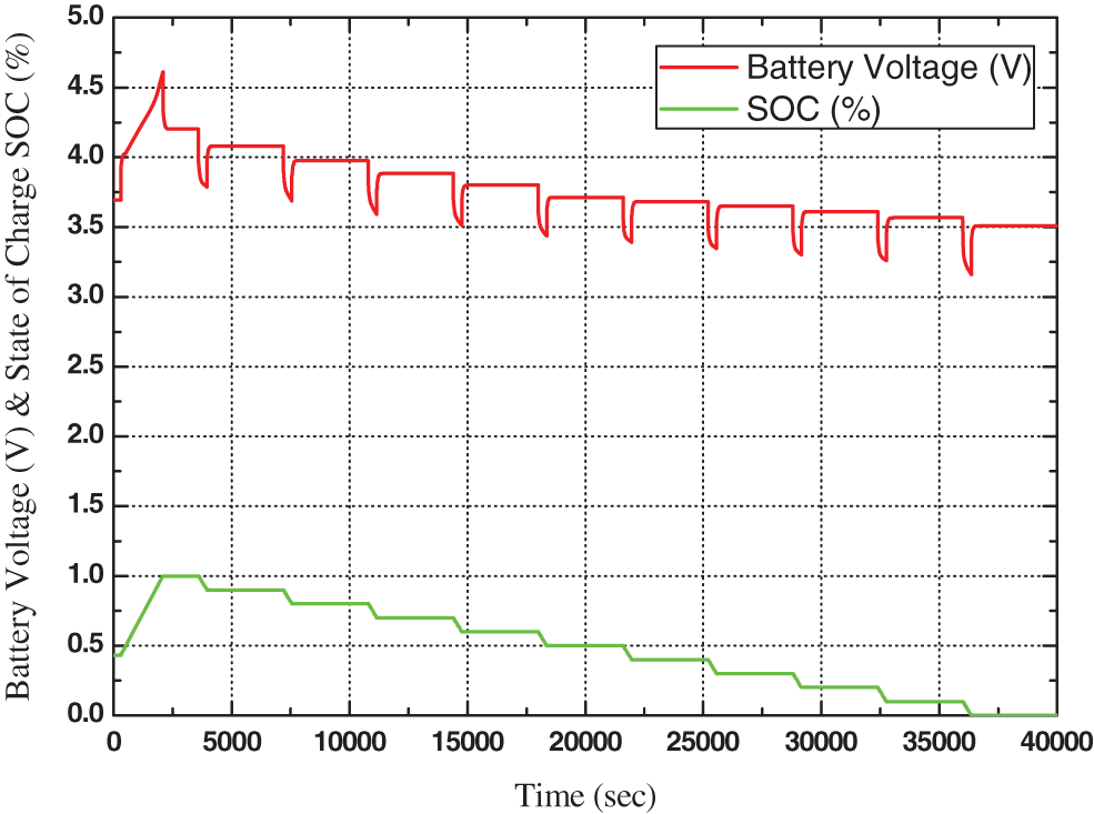
Figure 8: Battery voltage and SOC of battery OTC model
The proposed PV-BSS with MPPT techniques was simulated in MATLAB/SIMULINK software environment as shown in Fig. 9. Initially, the proposed PV-BSS operates at D = 0.16
The variation of PV voltage, Battery voltage, Battery power, and SOC of battery without MPPT technique will be illustrated below from Fig. 10.

Figure 9: The simulation model of PV-EES

Figure 10: Operation of PV-BSS without MPPT technique at different solar radiation and temperature
These figures show the effects of the irradiance (G) and temperature (T) variation in 4 cases mentioned in Fig. 4 every 600 s. As shown in Figs.10a and 10b, every 600 s there is a change in PV current and voltage due to irradiance and temperature change. The change in PV output is accompanied by a change in battery voltage and current with a reciprocal ratio. So, the power of PV & Battery is approximately the same as shown in Fig. 10c.
Where Fig. 10d illustrates the SOC of the battery, it is easily noticed that the rate of charging is changed every 600 s as irradiance and temperature change. Also, the BSS takes 2400 s to reach SOC equal 48.7%.
4 Simulation Model of On-line MPPT Techniques
In this part; three different online MPPT techniques are discussed. P&O and IncCond techniques are conventional hill-climbing techniques that are based on measurements of PV voltage and currents then the duty cycle is varied until the MPP is reached. The third technique is a novel methodology based on using solar irradiance and cell temperature measurements with pre-build ANFIS model to predict the optimum duty cycle to reach MPP.
P&O, IncCond and ANFIS-based techniques are used as an online MPPT controller to investigate the proposed study under different environmental conditions, so intensive works are conducted.
The P&O technique is based on periodical measurement of PV current I(k) and voltage V(k) to determine the actual PV output power P(k), then flowing steps are repeated until MPP is reached:
1) Perturb; varying the power converter duty cycle D up and down.
2) Observe; determining the output power variation (ΔP) sign and the PV voltage variation (ΔV) sign.
3) If ΔP and ΔV have different signs, the perturb step should be kept in the same direction otherwise the direction will be reversed.
4) For more accuracy, lower oscillation, and fast reaching to the MPP, variable step size is used [13]
The previous steps can be summarized in the flow chart of the P&O technique, which is shown in Fig. 11a. For every previous change in PV current and voltage due to irradiance and temperature change the optimum Duty cycle obtained by the P&O technique is shown in Fig. 11b.
The IncCond technique is based on periodical measurement of PV current I(k) and voltage V(k) to determine the actual instantaneous conductance I(k)/V(k), then flowing steps are repeated until MPP is reached [13]:
1) Varying the power converter duty cycle D up and down.
2) Determining the PV current variation (ΔI) and the PV voltage variation (ΔV) and incremental conductance ΔI/ΔV.
3) If ΔV
4) If ΔV

Figure 11: P&O MPPT algorithm
The previous steps can be summarized in the IncCond technique flow chart, which is shown in Fig. 12a
For every previous change in PV current and voltage due to irradiance and temperature change the optimum Duty cycle obtained by the IncCond technique is shown in Fig. 12b

Figure 12: IncCond MPPT algorithm
The ANFIS-based algorithm uses a periodical measurement of the radiation level and cell temperature as inputs of a network; and the optimal Duty cycle Dopt as an input of the network.
The optimal Duty cycle Dopt can be estimated by solving Eqs. (4), (5), (10), (12) and (13). Due to the nonlinearity, the complexity of the PV-BSS and ANFIS-based algorithm is to be employed. This can be mathematically expressed as follows;
So the ANFIS model can be built by using actual data of G, T, and Dopt that based upon a first order Takagi–Sugeno model consisting of five layers. The membership functions are chosen to be trimf membership function for all the inputs where it gives good outputs compared to the other membership functions With RMSE = 0.00045212.
For every previous change in PV current and voltage due to irradiance and temperature change the optimum Duty cycle obtained by ANFIS-based technique is shown in Fig. 13.

Figure 13: Optimum duty cycle with time with ANFIS-based MPPT algorithm at different solar radiation and working temperature
5 Operation of PV-BSS Based on On-Line MPPT Techniques
The operation of PV-based battery storage system using IncCond, P&O, and ANFIS based techniques under different environmental conditions is done below. Illustrating the performance characteristics of PV-BSS and evaluating the validity and the accuracy of proposed models under variable climates conditions are achieved by simulation works.
5.1 On-Line MPPT Techniques Evaluation
For every previous change in irradiance and temperature change, the PV and Battery voltage and current obtained by IncCond, P&O, and ANFIS-based techniques are shown in Fig. 14.
Tabs. 2 and 3 show a comparison between different MPPT algorithms and their effect on PV & Battery Voltage and current. From obtained data, it is easily deduced that ANFIS-based techniques is the best MPPT technique according to the range, standard deviation, and relation between mean, median and mode for instantaneous PV and battery voltage.

Figure 14: Voltage and current of PV-BSS with different MPPT algorithms at different solar radiation & temperature

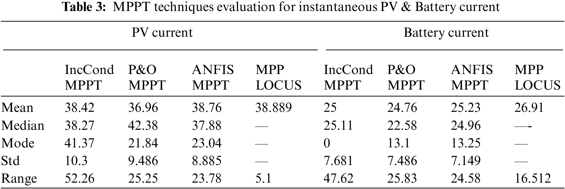
For Voltage waveform; ANFIS-based technique has a lower range and standard deviation which means lower oscillation as noticed in Tab. 2. Besides the mean, median and mode are approximately equal which means a more symmetrical voltage waveform. Also, lower overshot for ANFIS-based technique as noticed in Fig. 14a.
Also for the current waveform; ANFIS-based technique has a slight lower range and standard deviation which means lower oscillation as noticed in Tab. 3. But it is noticed that current has more oscillation than voltage waveform. Also the mean, median, and mode are not equal which means not symmetrical waveform. But still, ANFIS-based technique is slight best waveform as noticed in Fig. 14b
Fig. 15a and Tab. 4 show a comparison between different MPPT algorithms and their effect on Battery power. It is easily noticed that ANFIS-based technique is the best MPPT technique.

Figure 15: Power & SOC of BSS with different MPPT algorithms at different solar radiation & temperature

where, Fig. 15b illustrates the SOC of the battery obtained by different MPPT techniques. It is easily noticed that a significant improvement of SOC as the BSS takes 2400 s to reach SOC equal 70.94%, 71.03%, and 71.73% for IncCond, P&O, and ANFIS based MPPT techniques respectively.
A novel approach for online MPPT for PV-BSS operation based on ANFIS Technique is discussed, implemented and assessed. Besides conventional hill-climbing techniques P& O, and IncCond techniques are also introduced and evaluated.
The main results present in this article can be summarized as shown below;
1) A valued reference model of PV-BSS is introduced with full analyses
2) Evaluation study of On-Line MPPT Algorithms of PV-BSS is introduced with full analyses
3) P&O, IncCond and ANFIS based techniques are presented
4) Significant increase of SOC for proposed methodology to 147.3% from (84.7% without MPPT to 71.73% with MPPT).
5) Get a novel SC method to predict the optimal duty cycle to track the MPP with variable climate conditions.
6) Approximately equal duty cycle prediction from SC MPPT model and analytical model with MSSE of 0.000083 for the worst case.
7) Then modeling of PV-BSS operation with P&O, IncCond and ANFIS-based techniques is discussed.
8) Also evaluation of P&O, IncCond and ANFIS-based techniques is introduced and ANFIS based technique is proved as the best online MPPT technique with lower oscillation.
This model may be very useful for more works such as studying the partial shading effects, different types of batteries, and discussing the effect of SC MPPT techniques on SOC.
Acknowledgement: The authors are thankful to the Deanship of Scientific Research at Najran University for funding this work under the General Research Funding program grant code (NU/-/SERC/10/650).
Funding Statement: The Deanship of Scientific Research at Najran University has supported this work, under the General Research Funding program grant code (NU/-/SERC/10/650).
Conflicts of Interest: The authors declare that they have no conflicts of interest to report regarding the present study.
1. International Renewable Energy Agency Platform IRENA, “Renewable capacity statistics 2021,” [Accessed 18 January 2022], 2021. [Google Scholar]
2. M. Sechilariu, B. Wang and F. Locment, “Building integrated photovoltaic system with energy storage and smart grid communication,” IEEE Transactions on Industrial Electronics, vol. 60, no. 4, pp. 1607–1618, 2013. [Google Scholar]
3. X. Xu, M. Bishop, D. G. Oikarinen and C. Hao, “Application and modeling of battery energy storage in power systems,” CSEE Journal of Power and Energy Systems, vol. 2, no. 3, pp. 82–90, 2016. [Google Scholar]
4. International Energy Agency Platform IEA, “Renewables 2021, Global Status Report,” [Accessed 18 January 2022], 2021. [Google Scholar]
5. J. Parnell, “2020: The year of green hydrogen in 10 stories,” Green Tech Media [Accessed 18 January 2022]2020. [Google Scholar]
6. G. Chaudhary, J. J. Lamb, O. S. Burheim and B. Austbø, “Review of energy storage and energy management system control strategies in micro-grids,” Energies, vol. 14, no. 16, pp. 1–25, 2021. [Google Scholar]
7. E. Hossain, H. M. R. Faruque, M. S. H. Sunny, N. Mohammad and N. Nawar, “A comprehensive review on energy storage systems: Types, comparison, current scenario, applications, barriers, and potential solutions, policies, and future prospects,” Energies, vol. 13, no. 14, pp. 3651, 2020. [Google Scholar]
8. H. A. Behabtu, M. Messagie, T. Coosemans, M. Berecibar, K. A. Fante et al., “A review of energy storage technologies’ application potentials in renewable energy sources grid integration,” Sustainability, vol. 12, no. 24, pp. 1–20, 2020. [Google Scholar]
9. Z. Huang, P. Luo, S. Jia, H. Zheng and Z. Lyu, “A sulfur-doped carbon-enhanced Na3V2(PO4)3 nano-composite for sodium-ion storage,” Journal of Physics and Chemistry of Solids, vol. 167, pp. 1–10, 2022. [Google Scholar]
10. A. Y. Yassin, “Impedance, structural and thermal analyses of polyvinyl alcohol/polyvinyl pyrrolidone blend incorporated with Li+ ions for lithium-ion batteries,” Journal of Materials Research and Technology, vol. 15, pp. 754–767, 2021. [Google Scholar]
11. Y. Zhang, Z. Qiu, Z. Wang and Sh Yuan, “Functional polyethylene separator with impurity entrapment and faster Li+ ions transfer for superior lithium-ion batteries,” Journal of Colloid and Interface Science, vol. 607, no. 1, pp. 742–751, 2022. [Google Scholar]
12. M. A. Farahat, M. A. Enany and A. Nasr, “Assessment of maximum power point tracking techniques for PV system applications,” Journal of Renewable and Sustainable Energy, vol. 7, no. 4, pp. 1–10, 2015. [Google Scholar]
13. M. A. Enany, M. A. Farahat and A. Nasr, “Modeling and evaluation of main maximum power point tracking algorithms for photovoltaics systems,” Renewable and Sustainable Energy Reviews, vol. 58, no. 4, pp. 1578–1586, 2016. [Google Scholar]
14. D. Baimel, S. Tapuchi, Y. Levron and J. Belikov, “Improved fractional open circuit voltage MPPT methods for PV systems,” Electronics, vol. 8, no. 3, pp. 321, 2019. [Google Scholar]
15. J. Mroczka and M. Ostrowski, “A low-cost maximum power point tracker with the hybrid algorithm that uses temperature measurement,” in 2019 8th Int. Conf. on Renewable Energy Research and Applications (ICRERA), Brasov, Romania, pp. 445–449, 2019. [Google Scholar]
16. S. A. Ibrahim, A. Nasr and M. A. Enany, “Maximum power point tracking using ANFIS for a reconfigurable PV-based battery charger under non-uniform operating conditions,” IEEE Access, vol. 9, pp. 114457–114467, 2021. [Google Scholar]
17. M. A. Enany, “Cuckoo search based MPPT controller for PV water pumping system,” Journal of Renewable and Sustainable Energy, vol. 9, no. 6, pp. 1–10, 2017. [Google Scholar]
18. B. Yang, T. Zhu, J. Wang, H. Shu, T. Yu et al., “Comprehensive overview of maximum power point tracking algorithms of PV systems under partial shading condition,” Journal of Cleaner Production, vol. 268, no. 5, pp. 1–21, 2020. [Google Scholar]
19. M. M. Ahmed, W. S. Hassanien and M. A. Enany, “Modeling and evaluation of SC MPPT controllers for PVWPS based on DC motor,” Energy Reports, vol. 7, no. supplement issue 1, pp. 6044–6053, 2021. [Google Scholar]
20. A. R. Reisi, M. H. Moradi and S. Jamasb, “Classification and comparison of maximum power point tracking techniques for photovoltaic system: A review,” Renewable and Sustainable Energy Reviews, vol. 19, no. 4, pp. 433–443, 2013. [Google Scholar]
21. N. A. Elsonbaty, M. A. Enany and M. M. Gamil, “Modeling of a directly coupled PV water pumping system using soft computing techniques,” in Michael Faraday IET International Summit–2015, MFIIS(2015), Kolkata, India, pp. 554–559, 2015. [Google Scholar]
22. N. A. Elsonbaty, M. A. Enany and M. M. Gamil, “Soft computing modeling of a directly coupled PV water pumping system,” International Journal of Renewable Energy Research (IJRER), vol. 6, no. 1, pp. 99–105, 2016. [Google Scholar]
23. S. Hara, “Parameter extraction of single-diode model from module datasheet information using temperature coefficients,” IEEE Journal of Photovoltaic, vol. 11, no. 1, pp. 213–218, 2021. [Google Scholar]
24. H. Tian, F. Mancilla-David, K. Ellis, E. Muljadi and P. Jenkins, “A cell-to-module-to-array detailed model for photovoltaic panels,” Solar Energy, vol. 86, no. 9, pp. 2695–2706, 2012. [Google Scholar]
25. J. Jung and S. Ahmed, “Model construction of single crystalline photovoltaic panels for real-time simulation,” in 2010 IEEE Energy Conversion Congress and Exposition, Atlanta, GA, USA, IEEE, pp. 342–349, 2010. [Google Scholar]
26. W. De Soto, S. A. Klein and W. A. Beckman, “Improvement and validation of a model for photovoltaic array performance,” Solar Energy, vol. 80, no. 1, pp. 78–88, 2006. [Google Scholar]
27. A. Rahmoun and H. Biechl, “Modelling of Li-ion batteries using equivalent circuit diagrams,” PrzeglĄd Elektrotechniczny (Electrical Review), vol. 2012, no. 7b, pp. 152–156, 2012. [Google Scholar]
28. T. Huria, M. Ceraolo, J. Gazzarri and R. Jackey, “High fidelity electrical model with thermal dependence for characterization and simulation of high-power lithium battery cells,” in 2012 IEEE Int. Electric Vehicle Conf., pp. 1–8, 2012. [Google Scholar]
29. Siemens Solar Industries, “Solar module SM55,” [accessed 22.1.22]. [Online]. Available: http://www.solarquest.com/microsolar/suppliers/siemens/sm55.pdf. [Google Scholar]
Appendix A
The study system parameters are [29];

 | This work is licensed under a Creative Commons Attribution 4.0 International License, which permits unrestricted use, distribution, and reproduction in any medium, provided the original work is properly cited. |