DOI: 10.32604/cmes.2021.014129
ARTICLE
Damage Failure Analysis of Z-Pins Reinforced Composite Adhesively Bonded Single-Lap Joint
1School of Electromechanical Engineering, Lingnan Normal University, Zhanjiang, 524048, China
2Tianjin Key Laboratory of Integrated Design and On-line Monitoring for Light Industry & Food Machinery and Equipment, Tianjin University of Science & Technology, Tianjin, 300222, China
*Corresponding Author: Yinhuan Yang. Email: yangyh80@163.com
Received: 29 August 2020; Accepted: 23 October 2020
Abstract: In order to study the mechanical properties of Z-pins reinforced laminated composite single-lap adhesively bonded joint under un-directional static tensile load, damage failure analysis of the joint was carried out by means of test and numerical simulation. The failure mode and mechanism of the joint were analyzed by tensile failure experiments. According to the experimental results, the joint exhibits mixed failure, and the ultimate failure is Z-pins pulling out of the adherend. In order to study the failure mechanism of the joint, the finite element method is used to predict the failure strength. The numerical results are in good agreement with the experimental results, and the error is 6.0%, which proves the validity of the numerical model. Through progressive damage failure analysis, it is found that matrix tensile failure of laminate at the edge of Z-pins occurs first, then adhesive layer failure-proceeds at the edge of Z-pins, and finally matrix-fiber shear failure of the laminate takes place. With the increase of load, the matrix-fiber shear failure expands gradually in the X direction, and at the same time, the matrix tensile failure at the hole edge gradually extends in different directions, which is consistent with the experimental results.
Keywords: Z-pins reinforced composite adhesively bonded single-lap joints; failure mode; uniaxial tensile test; strength prediction; progressive damage
With the rapid development of science and technology, composite structures are widely used in aerospace and other fields. According to statistics, more than 70% of the structural failure of composite materials occurs in the joint. In addition, the whole oil tank and other parts have higher requirements on the connection structure, thus, the design and application level of composite structure are affected directly by the quality of composite material connection and assembly technology. The commonly used methods to improve the connection performance include bonding [1], mechanical connection [2], stitching [3], Z-pins [4,5] and so on. The Z-pins reinforcement technology is currently a new technology in the field of Composite Toughening. It can enhance the load bearing capacity of joints by inserting thin cylindrical nails into composite materials [6], which has the advantages of low cost and easy manufacturing. Pins can be made of metal or composite materials.
In recent years, great progress has been made in the research on the mechanical behavior of Z-pins reinforced composites [7–11]. The research on the failure mechanism and strength of Z-pins reinforced composite joints started relatively late, and there is relative few research on the progressive damage propagation behavior of Z-pins. Z-pins reinforcement technology can improve the shear strength of single-lap joints and pull-out strength of T-joints greatly. Nguyen et al. [12] studied the joints of pin reinforced composite materials and metal, and emphasized the important effects of strengthening the adhesion force between pins and composite materials on the mechanical properties of joints by means of experimental means, numerical simulation and theoretical analysis. Bodjona et al. [13] reviewed the references on hybrid bonding-fastening technology in recent years, focusing on two connection methods of composite structures. They mainly discussed the respective characteristics of hybrid bonding–bolt connection and hybrid bonding-pin connection, highlighted the blank areas in the literature, and predicted the future research. Solmaz et al. [14] carried out progressive damage failure analysis on the bonded and riveted double lap joints of braided composite materials. The maximum shear stress theory and Hashin failure criterion were applied to determine the joint failure load and mode. The results show that the strength of the joint is 2.72 times and 1.14 times higher than those of the single adhesive joint and the single mechanical connection joint, respectively. From fixture design to test result analysis, Kwon et al. [15] combined with numerical simulation method, carried out experimental and numerical research on laminated composite mechanical joint, and used the maximum stress theory, maximum strain theory and Tsai–Wu criterion to determine the failure load, displacement and strength of the joints.
In summary, because the damage mechanism of Z-pins reinforced composite bonding joints is more complicated than that of non-reinforced joints, the strength prediction and progressive damage of Z-pins reinforced composite bonded joints have attracted much attention of researchers, and have become a hot topic, and there is relative few research on the progressive damage propagation behavior of Z-pins reinforced T700/TDE86 Carbon Fiber/epoxy resin composite joints at present. Combined with the advantages of bonding technology and Z-pins reinforcement method, the uniaxial static tensile test of Z-pins reinforced T700/TDE86 unidirectional laminated composite SLJ was carried out in this paper. The failure mode and mechanism of the joints were analyzed. The strength prediction and progressive damage failure analysis of the joints were carried out by finite element method.
2 Test Specimen Material and Joint Structure
The Z-pins are T700 Carbon Fiber/epoxy resin composites with fiber volume content of 60%. The bonding zone adhesive is J39 epoxy adhesive, the adherend is T700/TDE86 epoxy resin matrix unidirectional laminate, the laying order is [0]10, and the fiber volume content is 60%.
Joint geometry configuration: the overall length of the joint test specimen is 200 mm, the lap length of the joint is 20 mm, the size of adherend is 25 mm in width and 2 mm in thickness, the thickness of adhesive layer is 0.3 mm, and the diameter, length and spacing of Z-pins are 0.8, 4.3 and 5 mm, respectively.
The geometry and Z-pins distribution of the Z-pins reinforced composite adhesively bonded SLJ are shown in Fig. 1.
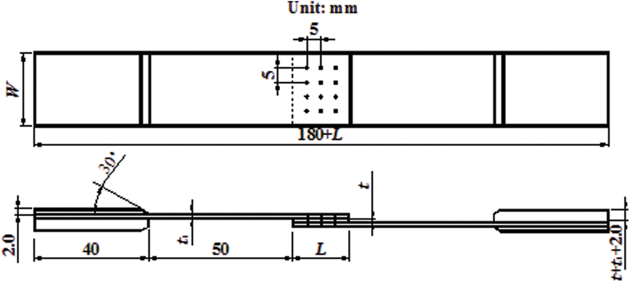
Figure 1: Z-pins reinforced composites adhesively bonded SLJ
An INSTRON (5569) universal electronic tension and compression testing machine is used to carry out the room temperature and quasi-static uniaxial tensile test, as shown in Fig. 2a. According to ASTM D 3165 [16], displacement controlled loading was adopted, and the longitudinal tensile loading rate was 1 mm/min. The test specimen is clamped as shown in Fig. 2b, and the testing machine is equipped with automatic data acquisition and processing system with high test accuracy. Since the load line of the joint does not pass through the geometric center of the SLJ, aluminum reinforcing plates with different thicknesses and the same length are pasted on both ends of the specimen in order to balance the structural form of the antisymmetric joint, which can not only prevent the specimen from being pinched, but also ensure that the load line acting on the specimen passes through the geometric center of the joint. The fiber direction of unidirectional laminate is  to the loading direction.
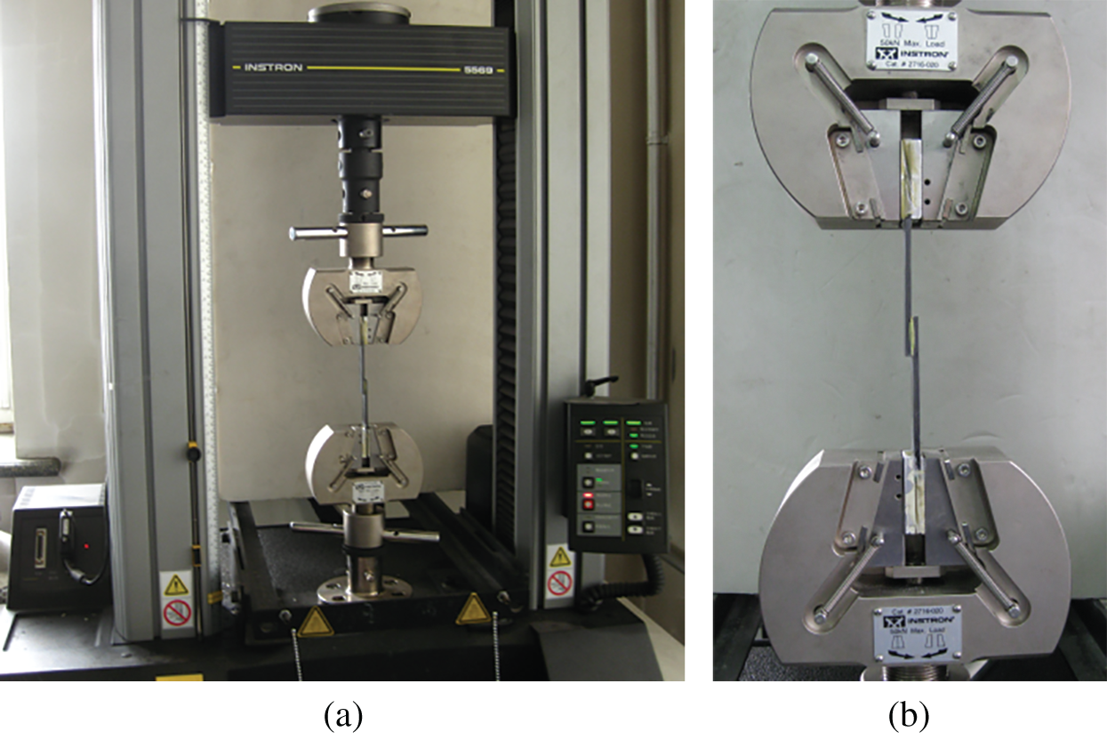
Figure 2: INSTRON (5569) test machine and griped specimen. (a) Test machine (b) griped specimen
The interface morphology of Z-pins reinforced composite adhesively bonded SLJ after failure is shown in Fig. 3. It can be found that the interface failure is the dominant failure mode of the joint. At the same time, with a small part of cohesive failure and fiber-tear failure, fiber tearing occurs in the laminate between Z-pins, and the final failure mode is Z-pins pulling out from the adherend. This kind of joint failure is also related to the material properties of Z-pins, and is greatly affected by the interfacial shear stress between Z-pins and joints.
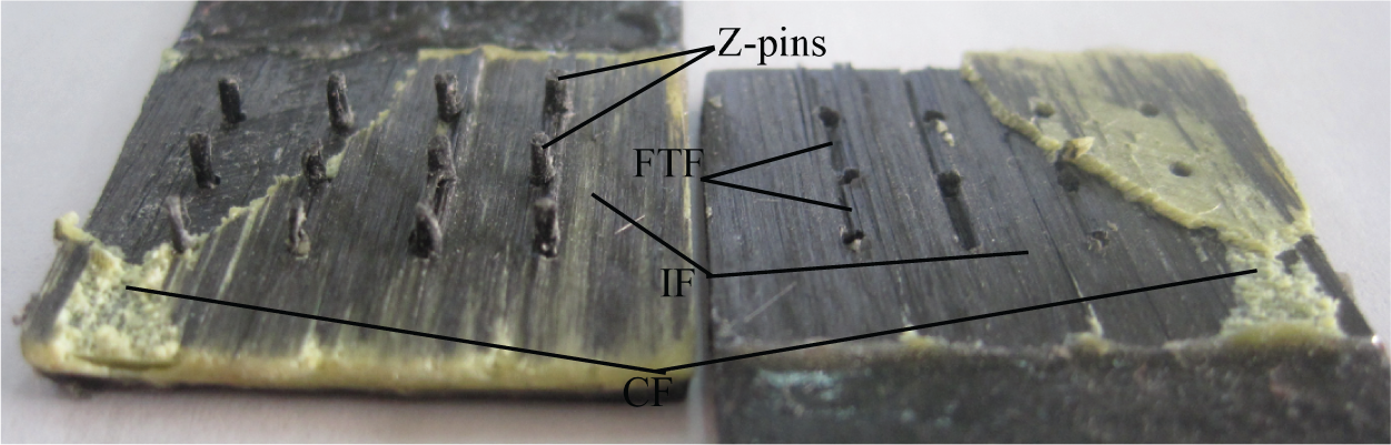
Figure 3: Failure modes of Z-pins reinforced composites SLJ (FTF–-fiber-tear failure, IF–-interface failure, CF–-cohesive failure)
3.3 Failure Mechanism Analysis
The load-displacement curve of Z-pins reinforced composite adhesively bonded SLJ under uniaxial tensile load is shown in Fig. 4. For single-lap joint, because the action line of the applied load is not the same line of the geometric center of the lap structure, the applied load will produce an eccentric bending moment, peel off the lap joint at the lap section, and also deform lap joint in the shear direction. Therefore, Z-pins are subject to both normal and shear stresses at the interface of the lap joint, and finally fail due to pulling out or breaking. The pulling-out and fracture of Z-pins are related to the tensile strength of Z-pins and the shear strength of adhesive layer between Z-pins and joints. In the experiments, no Z-pins fracture was found, and the final failure mode was Z-pins pulling out. Five tensile tests are conducted, the corresponding load-displacement relations are shown in Fig. 4. However, there is a big variation in the peak load. The difference of the peak values is mainly caused by process error and size error including thickness of adhesive layer, thickness of laminate and position of Z-pins and so on.
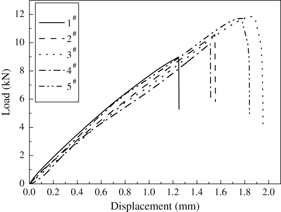
Figure 4: Load and displacement curves of Z-pins reinforced composites adhesively bonded SLJ
For the further analysis of the failure mechanism of T700/TDE86 unidirectional laminate adhesively bonded SLJ under uniaxial tensile load, the ANSYS 14.0 finite element software is used for numerical calculation, and the corresponding program is developed by using APDL language. The schematic illustration of adhesive zone model of Z-pins reinforced composites SLJ is shown in Fig. 5.
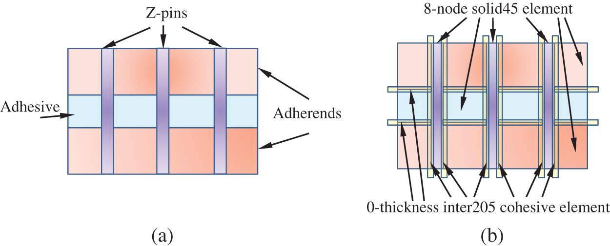
Figure 5: Schematic illustration of lap zone model of Z-pins reinforced composites SLJ. (a) The actual structure of Z-pins bonded joint (b) element types of lap zone model
To fundamentally analyze the bonded joint problem, the thin adhesive layer is modeled by the proposed adhesive process zone model (APZM) [17]. In this work, the actual geometric configurations of Z-pins reinforced composites SLJ are complex. A representative geometric configuration of the Z-pins bonded joint is treated as two adjacent adherend plates sandwiching a very thin adhesive layer, and Z-pins are inserted perpendicularly into the plates and the adhesive layer as shown in Fig. 5a. The failure mode of Z-pins reinforced bonded joints depends on loading conditions, and it could be matrix tensile failure, fiber tensile failure, matrix fiber shear failure, delamination, adhesive layer failure and mixture of multiple failures. To predict the correct failure mode under given loading condition, sudden degradation model is used to determine failure mode. To simulate the joint cracking and Z-pins peeling off in the joint, the laminates, Z-pins and adhesive layer are simulated by 8-node solid45 elements, and 0-thickness inter205 cohesive elements sharing nodes with the neighbouring solid elements are used to represent the interfaces between the laminates, adhesive layer and among Z-pins, as shown in Fig. 5b.
The adhesive layer is a linear elastic material, and the geometric nonlinearities of the adherend and Z-pins are considered respectively. The geometric parameters of the numerical calculation model of each joint are identical to those of the test specimen, with the X axis being in the length direction of the model, and the Y and Z axes being in the width and thickness directions, respectively.
4.1 Material Parameters, Loading and Meshing
The mechanical properties of unidirectional laminate and J39 adhesive are given in reference [18], the mechanical properties of Z-pin are shown in Tab. 1, and the relevant parameters of cohesive interface element are presented in Tab. 2. The constrained displacement and applied load are shown in Fig. 6, and the axial tensile force applied at the end is 9.0 kN. The mesh of the numerical model of the Z-pins reinforced joint is shown in Fig. 7, with the maximum element size of 2 mm and the minimum element size of 0.125 mm. Mesh was refined in areas at the end of lap joint and Z-pins, and around Z-pins.
Table 1: Mechanical properties of Z-pins (T700/ EPOXY)
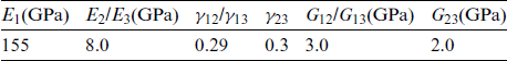
Table 2: Parameters of cohesive interface element
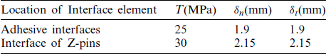
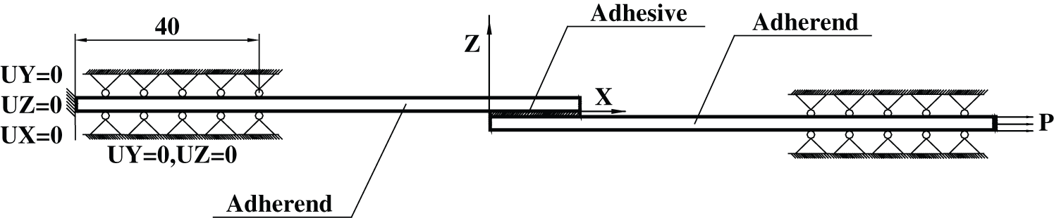
Figure 6: Constrained displacement and applied load
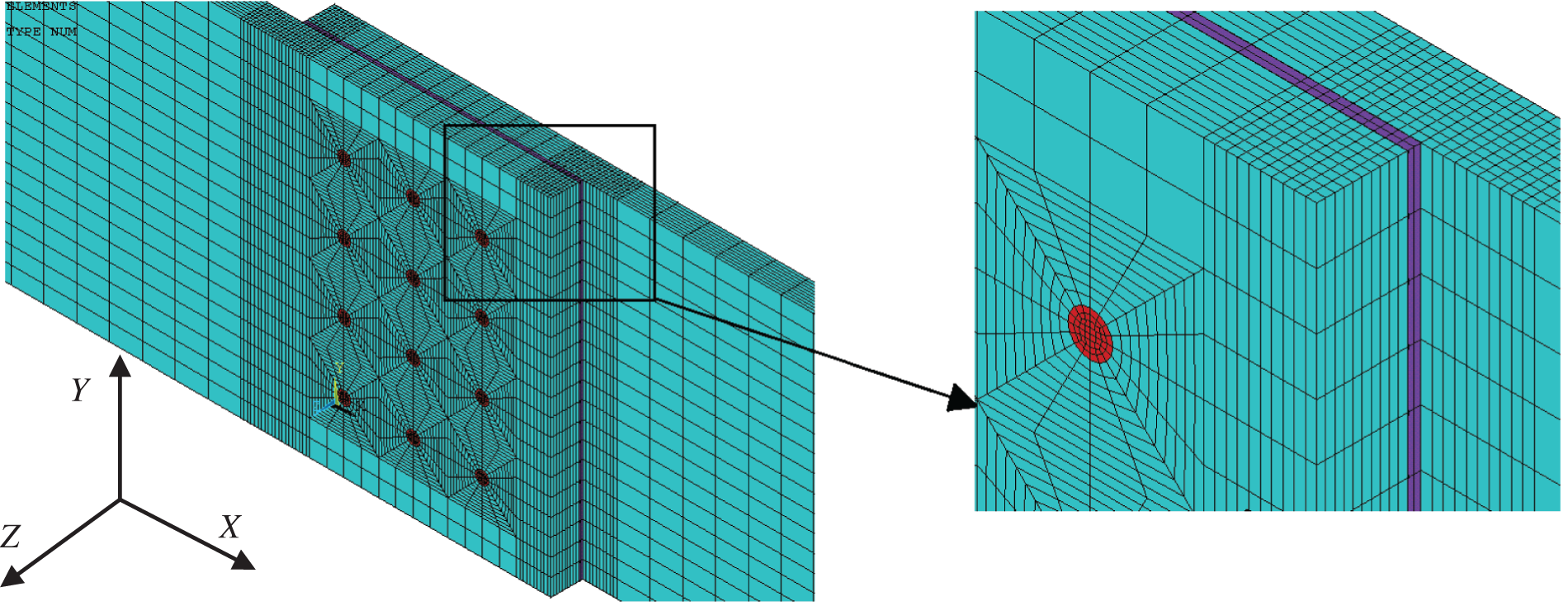
Figure 7: The mesh of the numerical model of Z-pins reinforced joint
The failure criteria of unidirectional laminates and adhesives are given in reference [18]. The quadratic criterion [19] is used for evaluating the stiffness reduction of cohesive interface elements in this paper, as given by

where,  –-Interlaminar stress,
 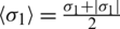 ;
;  ,
,  –-Interlaminar shear stress; T, S–-Tensile and shear strengths.
An important factor affecting the failure behavior of the cohesive interface element is the area under the force-displacement curve, i.e., energy release rate. Power index criterion based on energy [19] is used to assess the failure of cohesive elements in this paper. The expression is as follows:

where,  and
and  are the critical fracture energies of normal, tangential one and tangential two, respectively, and
  is the material parameter.
The failure process described in this model is monitored by failure parameter [19]. The expression of failure parameter is given as

where,  –-Displacement critical value of interface element stiffness reduction;
  –-Critical displacement value of interface element failure;
  –-Maximum effective displacement during loading.
The failure parameter is equal to 0 when it is before failure/damage initiation or just at the failure/damage initiation point, and is 1 at the final failure point. The failure process is analyzed by monitoring the change of the failure parameter.
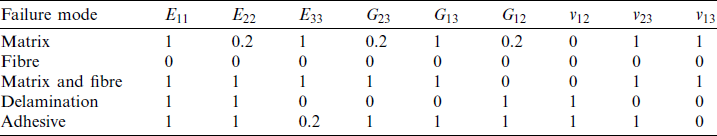
For Z-pins reinforced joints, with the increase of the load, the adhesive layer and adherend (such as the fiber or matrix of the laminate) will be damaged, and the material properties will degenerate in the damaged area. In this paper, combined with the material performance degradation method given by predecessors, it is assumed that if one element fails, the degradation of material properties only affects this element, no other elements. The damage propagation of different joints can be directly reflected by the damage degradation degree of the element material. According to the experimental results of joint failure, five failure modes including matrix tensile failure, fiber tensile failure, matrix fiber shear failure, delamination and adhesive layer failure are considered. These five failure modes all adopt sudden degradation model, and the degradation coefficient of material performance is shown in Tab. 3 [20].
Table 3: Degradation engineering material constants [20]
The load displacement curve of Z-pins reinforced composite adhesively bonded SLJ is shown in Fig. 8. The load displacement curve of test specimen  is compared with the numerical results, because the load displacement curve of test specimen
  is in the mean position of the load displacement curves of the five specimens. The numerical results show that when the uniaxial tensile load reaches 4.18 kN, matrix tensile failure occurs firstly at the hole edge of the laminate. When the load reaches 10.58 kN, matrix-fiber shear failure begins to appear at the interface near the hole of laminate.
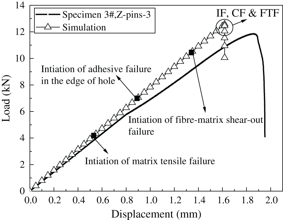
Figure 8: Load vs. displacement curves of Z-pins reinforced composite joint with three rows of pins (t = 0.32 mm, L = 20.08 mm, FTF–-fiber-tear failure, IF–-interface failure, CF–-cohesive failure)
The failure load of the joint obtained by numerical simulation is 12.57 kN, and the dominant failure mode of the joint is adhesive layer failure. The matrix tensile failure and a small part of matrix-fiber shear failure at the hole edge of the laminate are consistent with the failure mode of the test specimen. The predicted shear strength of the joint is 25.04 MPa, the experimental shear strength is 23.61 MPa, and the error is 6.0%. The numerical results are in good agreement with the experimental results, which proves the validity of the numerical model. The difference of the initial stiffness between the numerical simulation and the experimental measurement is mainly due to the slight differences between the material mechanical property parameters used in the numerical simulation and those of the experimental specimen. The reason is that various errors in the manufacturing process of the experimental specimen affect the material mechanical property parameters.
The damage propagation of Z-pins reinforced composite adhesively bonded SLJ is shown in Fig. 9. Since the pore size of the laminate is far smaller than the overall geometric size of the joint, the failure of the laminate is analyzed by taking the cell model at the hole edge as an example in order to clearly reflect the damage propagation process of the laminate. The cell model and location are shown in Fig. 9a.
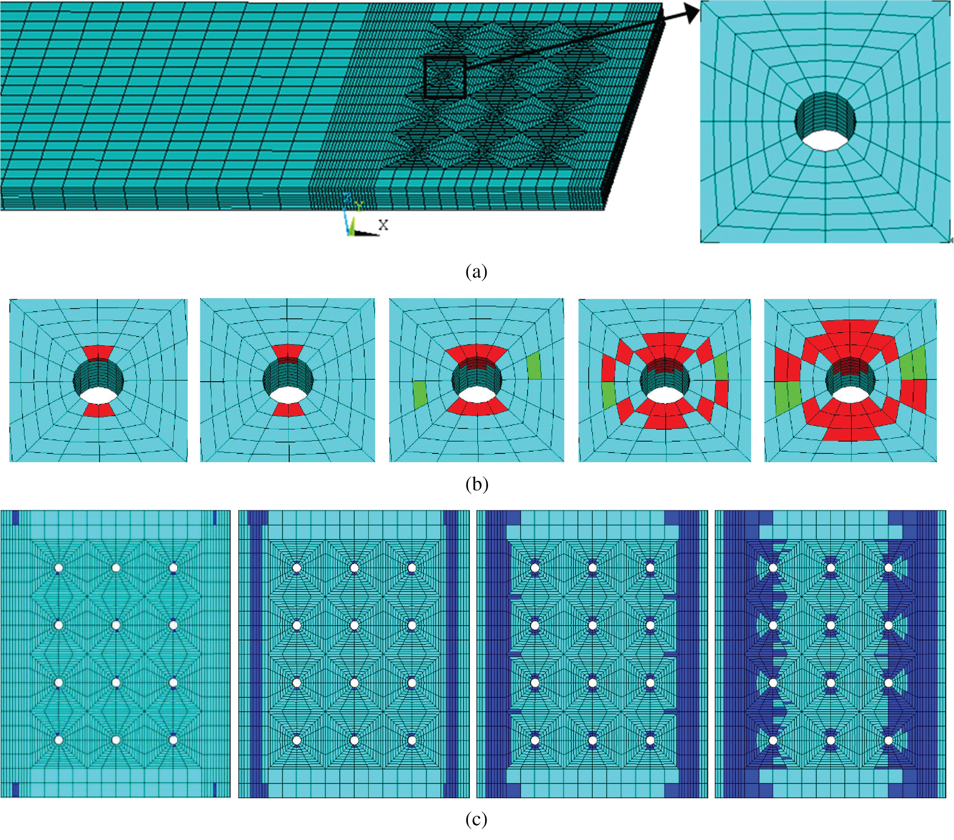
Figure 9: Damage evolution of Z-pins reinforced composites SLJ. (a) Model and location of single cell at the hole edge of the laminate (b) damage evolution at the hole edge of the laminate (c) evolution of adhesive damage
The progressive damage propagation process at the hole edge of laminates is shown in Fig. 9b. Red indicates matrix tensile failure and green indicates matrix-fiber shear failure. It can be appeared that when the load is 4.18 kN, the matrix tensile failure occurs at the interface position close to the hole edge thickness direction and the interface position in the Y direction. With the increase of load, the damage along the thickness direction and Y direction gradually expands. When the load reaches 10.58 kN, the matrix-fiber shear failure occurs along the x-direction at the hole edge interface of the laminate. With the increase of load, the matrix-fiber shear failure gradually expands along the X direction, and the matrix tensile failure at the hole edge expands along the X, Y and Z directions.
The damage propagation process of the adhesive layer is shown in Fig. 9c. When the load is 6.95 kN, the adhesive layer failure occurs firstly at the edge of the adhesive layer hole. With the increase of load, the damage propagation speed of the adhesive layer is slow, and the damage propagation is always in the small range of the hole edge at this stage. When the load reaches 10.45 kN, the shear failure occurs at the position 1.25 mm away from the free end in the X direction of the adhesive layer, and then the failure of the adhesive layer gradually extends from the end of the adhesive layer to both sides along the X direction until the final failure. The damage propagation of adhesive layer is approximately symmetrical.
The failure mechanism, strength prediction and progressive damage failure of Z-pins reinforced composite single lap adhesive joints are systematically studied from the aspects of experimental characterization and numerical simulation in this paper.
1. The failure mode of the joint is dominated by the thin layer cohesive failure, accompanied by a small part of interface failure and fiber-tear failure, and the final failure mode is Z-pins pulling out from the adherend.
2. The predicted shear strength of the joint is 25.04 MPa, the experimental shear strength is 23.61 MPa, and the error is 6.0%. The numerical results are in good agreement with the experimental results, which proves the validity of the numerical model.
3. The matrix tensile failure of laminate occurs first at the Z-pins edge, with the increase of load, the damage along the thickness direction and Y direction gradually expands, and then the damage of adhesive layer of Z-pins edge appears. The damage propagation of adhesive layer is approximately symmetrical, and finally the matrix-fiber shear failure of laminate occurs. With the increase of load, the matrix-fiber shear failure gradually expands in the X direction, and the matrix tensile failure at the hole edge expands in different directions, which are consistent with the experimental results.
Acknowledgement: The authors would like to thank the Editor and anonymous reviewers for their valuable comments and helpful suggestions to improve the quality of this manuscript.
Funding Statement: This work was supported by Natural Science Talents Program of Lingnan Normal University (No. ZL2021011).
Conflicts of Interest: The authors declare that they have no conflicts of interest to report regarding the present study.
1. Ozel, A., Yazici, B., Akpinar, S., Aydin, M. D., Temiz, Ş. (2014). A study on the strength of adhesively bonded joints with different adherends. Composites Part B: Engineering, 62, 167–174. DOI 10.1016/j.compositesb.2014.03.001. [Google Scholar] [CrossRef]
2. Nzabonimpa, J. D., Hong, W. K., Kim, J. (2018). Experimental and non-linear numerical investigation of the novel detachable mechanical joints with laminated plates for composite precast beam-column joint. Composite Structures, 185, 286–303. DOI 10.1016/j.compstruct.2017.11.024. [Google Scholar] [CrossRef]
3. An, W. J., Kim, C. H., Choi, J. H., Kweon, J. H. (2019). Static strength of RTM composite joint with I-fiber stitching process. Composite Structures, 210, 348–353. DOI 10.1016/j.compstruct.2018.11.072. [Google Scholar] [CrossRef]
4. Warzok, F., Allegri, G., Gude, M., Hallett, S. R. (2016). Experimental characterisation of fatigue damage in single Z-pins. Composites Part A: Applied Science and Manufacturing, 91, 461–471. DOI 10.1016/j.compositesa.2016.03.023. [Google Scholar] [CrossRef]
5. Ko, M. G., Kweon, J. H., Choi, J. H. (2015). Fatigue characteristics of jagged pin-reinforced composite single-lap joints in hygrothermal environments. Composite Structures, 119, 59–66. DOI 10.1016/j.compstruct.2014.08.025. [Google Scholar] [CrossRef]
6. Cui, H., Yasaee, M., Hallett, S. R., Partridge, I. K., Allegri, G. et al. (2018). Dynamic bridging mechanisms of through–thickness reinforced composite laminates in mixed mode delamination. Composites Part A: Applied Science and Manufacturing, 106, 24–33. DOI 10.1016/j.compositesa.2017.11.017. [Google Scholar] [CrossRef]
7. Blacklock, M., Joosten, M. W., Pingkarawat, K., Mouritz, A. P. (2016). Prediction of mode I delamination resistance of z-pinned laminates using the embedded finite element technique. Composites Part A: Applied Science and Manufacturing, 91, 283–291. DOI 10.1016/j.compositesa.2016.10.008. [Google Scholar] [CrossRef]
8. Song, Q., Li, Y., Qi, J., Wen, L., Xiao, J. et al. (2014). Study on an automatic multi-pin insertion system for preparing Z-pin composite laminates. Chinese Journal of Aeronautics, 27(2), 413–419. DOI 10.1016/j.cja.2014.02.012. [Google Scholar] [CrossRef]
9. Zhang, B., Allegri, G., Yasaee, M., Hallett, S. R., Partridge, I. K. (2016). On the delamination self-sensing function of Z-pinned composite laminates. Composites Science and Technology, 128, 138–146. DOI 10.1016/j.compscitech.2016.03.019. [Google Scholar] [CrossRef]
10. Zhang, B., Allegri, G., Hallett, S. R. (2016). An experimental investigation into multi-functional Z-pinned composite laminates. Materials & Design, 108, 679–688. DOI 10.1016/j.matdes.2016.07.035. [Google Scholar] [CrossRef]
11. Yasaee, M., Bigg, L., Mohamed, G., Hallett, S. R. (2017). Influence of Z-pin embedded length on the interlaminar traction response of multi-directional composite laminates. Materials & Design, 115, 16–36. [Google Scholar]
12. Nguyen, A. T. T., Brandt, M., Feih, S., Orifici, A. C. (2016). Pin pull-out behaviour for hybrid metal-composite joints with integrated reinforcements. Composite Structures, 155, 160–172. DOI 10.1016/j.compstruct.2016.07.047. [Google Scholar] [CrossRef]
13. Bodjona, K., Lessard, L. (2016). Hybrid bonded-fastened joints and their application in composite structures: A general review. Journal of Reinforced Plastics and Composites, 35(9), 764–781. DOI 10.1177/0731684415627296. [Google Scholar] [CrossRef]
14. Solmaz, M. Y., Topkaya, T. (2013). Progressive failure analysis in adhesively, riveted, and hybrid bonded double-lap joints. Journal of Adhesion, 89(11), 822–836. DOI 10.1080/00218464.2013.765800. [Google Scholar] [CrossRef]
15. Kwon, J. S., Kim, J. S., Lee, S. Y., Bae, J. S. (2017). A mechanically fastened composite laminate joint and progressive failure analysis. Advanced Composite Materials, 27(4), 439–456. DOI 10.1080/09243046.2017.1405607. [Google Scholar] [CrossRef]
16. ASTM D 3165-00. (2002). Standard test method for strength properties of adhesive in shear by tension loading of single-lap-joint laminated assemblies. Annual Book of Standards. Copyright ASTM, 100 Barr Harbor Drive, West Conshohocken, PA 19428-2959, USA. [Google Scholar]
17. Ren, B., Li, S. (2014). Multiscale modeling and prediction of bonded joint failure by using an adhesive process zone model. Theoretical and Applied Fracture Mechanics, 72, 76–88. DOI 10.1016/j.tafmec.2014.04.007. [Google Scholar] [CrossRef]
18. Yang, Y. H., Zhou, Z. G., Guo, Y., Wu, L. Z. (2012). Effect of defects in the adhesive layer on strength of adhesively bonded single-lap composites joints. Acta Materiae Compositae Sinica, 29(5), 157–163. [Google Scholar]
19. Yang, X. H., Hu, K. J., Zhao, N., Li, J. (2010). The simulation of the process of laminal damage in the adhesive bonded joint using the cohesive interface element. Computer Simulation, 10, 317–320. [Google Scholar]
20. Yang, Y. H. (2013). Progressive failure analysis of adhesively bonded laminates joints with spew fillets. Advanced Materials Research, 690–693, 2635–2638. DOI 10.4028/www.scientific.net/AMR.690-693.2635. [Google Scholar] [CrossRef]
 | This work is licensed under a Creative Commons Attribution 4.0 International License, which permits unrestricted use, distribution, and reproduction in any medium, provided the original work is properly cited. |