DOI: 10.32604/cmes.2021.014142
ARTICLE
On Ductile Damage Modelling of Heterogeneous Material Using Second-Order Homogenization Approach
Faculty of Mechanical Engineering and Naval Architecture, University of Zagreb, Zagreb, 10000, Croatia
*Corresponding Author: Jurica Sorić. Email: jurica.soric@fsb.hr
Received: 03 September 2020; Accepted: 11 November 2020
Abstract: The paper deals with the numerical modelling of ductile damage responses in heterogeneous materials using the classical second-order homogenization approach. The scale transition methodology in the multiscale framework is described. The structure at the macrolevel is discretized by the triangular C1 finite elements obeying nonlocal continuum theory, while the discretization of microstructural volume element at the microscale is conducted by means of the mixed type quadrilateral finite element with the nonlocal equivalent plastic strain as an additional nodal variable. The ductile damage evolution at the microlevel is modelled by using the gradient enhanced elastoplasticity. The macrolevel softening is governed by two criterions expressed by the increase in homogenized damage variable and the threshold of the local equivalent strain. The softening at each material point at the macrolevel is detected by the critical value of the homogenized damage, where homogenization of the damage variable is performed only within softening area. Due to the nonlocal continuum theory applied, a realistic softening behaviour is demonstrated after the damage initiation, compared to the widely used first-order homogenization approach. All algorithms derived have been embedded into the finite element code ABAQUS by means of the user subroutines and verified on the standard benchmark problems. The damage evolution at both microlevel and macrolevel has been demonstrated.
Keywords: Ductile damage; second-order homogenization; multiscale approach; C1 finite element
It is well-known that the heterogeneities appearing at the material microscale, such as porosities, inclusions and various kinds of defects may lead to undesired phenomena like damage and material softening, which can result in loss of structural load-carrying capacity as well as structural integrity. Derivation of numerically efficient and accurate algorithms connecting both microstructural and macrostructural deformation responses still remains a challenge in the scientific and engineering community.
The conventional numerical approaches employing softening constitutive behaviour are unable to adequately model the microstructural deformation [1–3]. This is a direct consequence of the basic assumptions of the classical local continuum theory concerning the material point concept and homogeneity. On the other hand, from physical and numerical standpoint, the nonlocal models have shown very good regularization abilities [4]. Based on the definition and implementation into constitutive model, nonlocal gradient theories can be divided into explicit and implicit. In explicit methods, the nonlocal field is defined as an extension of the corresponding local one by high-order members [5]. Implicit approaches are dealing with additional differential equations relating between local and nonlocal variables which should be solved simultaneously [6]. Furthermore, the most recent approach to fracture modelling is the phase-field framework [7] which seems to be very effective for handling complex fracture processes concerning with crack branching or curvilinear crack paths [8] and it is well-suited for problems such as brittle and ductile fracture [9]. The variational phase-field approach to fracture can be considered as a special type of the gradient damage models where the sharp crack discontinuity is approximated by a smeared surface using the phase-field variable which continuously varies over the domain and differentiates between fully broken and intact material phases [10].
From physical standpoint, explicit modelling of the complete material microstructure, and considering of all relevant microstructural governing mechanisms is the most accurate approach for modelling of material response. Unfortunately, modelling with such high fidelity still represents burdensome task for engineering practices. Therefore, efficient computational strategies based on multiscale procedures have been developed, incorporating physical understanding of material behaviour at the lower scales [11–15] in order to describe the response of coarse scale problems. Therein, the boundary value problem (BVP) driven by macroscopic quantities has been solved over a sample of material called representative volume element (RVE). In this framework, the computational homogenization has been proven as highly versatile [16].
The formulation of the second-order homogenization relies on employment of the nonlocal continuum theory at the macrolevel, where surrounding material influences on the behaviour of a considered material point [17,18]. The microstructural scale is usually described by ordinary local continuum, but the nonlocal theory can be appointed to the microscale too, as presented in the authors’ previous work [19]. The nonlocal theory adopted at macroscale is mostly based on the Mindlin’s theory [20,21], as it is the case in this contribution. The other approaches are also applicable, as in [22], where the Aifantis theory has been utilized.
Unfortunately, the utilization of the computational homogenization for softening materials seems to be questionable. One of the reasons is satisfaction of the scale separation principle which states that the RVE size should be much smaller than variation of the macrolevel loading [23], except when there is no clear distinction between scales or when scale separation is not applicable. For the first-order homogenization, this means that only constant strain can be imposed on the RVE boundaries [24,25]. This represents a limitation when softening phenomena appears at the microscale, considering the fact that during localization, strains within macrolevel localization band are distributed in highly nonlinear manner, which should be prescribed on the RVE in constant manner (first-order scheme) or in linear manner (second-order scheme). On the other hand, it has already been mentioned that the classical continuum theory in combination with the usual numerical approaches cannot regularize the formation of strain localization. Also, it has been demonstrated in [26,27] that the RVE loses its representativeness during the localization. Therefore, in the last few years, there are many proposals how to bridge material constitutive behaviour between scales when softening is initiated. Considering constitutive behaviour, the brittle damage and linear elasticity simulations have been more fruitful compared to the modelling of ductile damage and elastoplastic material responses. For example, the multigrid methods employ overlay discretization of the microstructure over the macroscopic model at the hotspots, where damage is anticipated [28] or disassemble the coarse scale model in the interest zones [29]. But, in this case the localization formation should be a priori known. An another approach introduces macroscale discontinuity enrichments, governed by the localization formation at the MVE (microstructural volume element) [30]. However, this method relies on the assumption that the constitutive behaviour of surrounding materials is linear elastic only. Regarding ductile damage, the multiscale method for description of the softening in polycrystalline materials has been proposed in [31], where the integral nonlocal terms are introduced in order to preserve objectivity of the results. In [32], the ductile damage in heterogeneous materials is described by means of the mean field homogenization, with an addition of isotropization procedure. As explained in the paper, the method is suited only for mild damage. The “Failure Oriented Multiscale Formulation” for consistent upscaling of the ductile softening behaviour has been presented in [33], with an emphasis on the RVE boundary conditions during the localization. A multiscale approach which employs strong coupling between scales has been presented in [34], based on the principle of the operator split on a two-phase material.
An efficient multiscale method for modelling of damage responses at microlevel still remains an open question. A first-order homogenization multiscale scheme for modelling of ductile damage has been proposed by the authors in [35]. Therein, the homogenization at the microlevel has been performed over the two microstructural samples representing two boundary value problems. One is without damage, where only elastoplastic response has been computed, and another is with the embedded nonlocal ductile damage model to compute softening evolution. Besides, the additional microstructural boundary value problems had to be solved in order to numerically compute the derivatives of damage variable with respect to three macrostrain components, which are necessary for the complete macrostructural constitutive matrix. It means, the five microstructural volume element (MVE) computations should be performed at every macrolevel material point. The standard displacement based finite elements have been used for discretization at the macrolevel, while the microstructural homogenization including damage has been carried out employing the mixed finite element formulation with nonlocal equivalent plastic strain interpolation. The benchmark examples show that the softening evolution has been captured correctly, and physically realistic structural responses have been modelled. However, it is easy to conclude that the microstructural homogenization procedure, employing the multiple MVE microscale computations, is complex and time demanding.
In another contribution by the authors [36], a two scale procedure for quasi brittle damage modelling has been shown, where the macrolevel localization, modelled by means of the nonlocal continuum theory, is governed by the microlevel damage responses. Therein, using the standard microstructural averaging procedure, an accurate and mesh independent damage evolution at the macrolevel has been obtained. On the other hand, in the case when the classical continuum theory and C0 continuity finite elements have been applied at the macroscale, the wrong results have been computed. Therefore, the authors’ idea is to use a standard averaging procedure with only one MVE at the microscale and to employ the nonlocal continuum theory with C1 continuity finite element discretization at the macrolevel in order to simplify the computation procedure, rather than complicate ductile damage modelling, where the five MVE computations have to be performed.
Hence, in this paper a second-order homogenization procedure using standard averaging approach is employed for the computation of ductile damage in heterogeneous materials. The nonlocal theory embedded into the triangular C1 finite element formulation is used for discretization at the macrolevel. The constitutive matrices are upscaled from the microlevel, where they are computed by the homogenization. Using one MVE, the implicit gradient-enhanced elastoplasticity, employing the von Mises yield function is applied for the consideration of softening behaviour. The microstructural discretization is performed by using the quadrilateral mixed finite element formulation including the nonlocal equivalent plastic strain interpolation. Therein, the homogenization procedure is much simpler than in the previous contribution [35]. Instead of five MVEs, only one is considered. However, the disadvantage of the newly proposed approach is the computation of state variables for greater number of material points at macrolevel, as a consequence of using high order triangular finite element satisfying C1 continuity. Instead of 4 integration points associated to the classical quadrilateral finite elements, 13 integration points are used in the finite element formulation obeying C1 continuity. It is important to mention, that theoretical parts of the paper have already been considered in the authors’ previous works. Therefore, they have been presented here only shortly. The original contribution of the paper is a new methodology for computation of ductile damage evolution in heterogeneous materials.
The paper is organized as follows. In Section 2, the triangular finite element satisfying C1 continuity is shortly discussed. Section 3 gives an insight into the mixed finite element formulation employed at the microscale, ensuring objective results for the ductile softening phenomena. The second-order homogenization methodology is also briefly discussed. In Section 4 the scale transition strategy with the emphasis on the upscaling procedure is presented. Section 5 deals with the usual benchmark problems considering an academic sample of heterogeneous material, where the physically realistic results are demonstrated. In Section 6 some concluding remarks are given.
2 Macrolevel Finite Element Formulation
As explained before, the second-order homogenization methodology relies on application of the nonlocal continuum theory at the macroscale. Accordingly, the macrolevel discretization has been performed by using the C1 triangular finite element which has been derived in the previous authors’ contributions [19,37] and it is not repeated here. Therefore, the main expressions are only presented very briefly. The element is shown in Fig. 1, adopting small strain assumption and plane strain condition. It consists of three nodes, each with twelve degrees of freedom (DOF), and the displacement field is approximated by the condensed fifth order polynomial. The nodal degrees of freedom are the displacements and their first and second spatial derivatives with respect to the Cartesian coordinates. The formulation described could be extended to the 3D formulation which requires much more complicate tetrahedral C1 finite elements.

Figure 1: C1 triangular finite element
According to the nonlocal theory, the element equations are derived from the principle of virtual work which may be expressed as:

where  and
and  are the stress and double stress, while
  and
and  are the strain and double strain tensors, respectively. u is the displacement vector, and the values t and T represent the traction and double surface traction, respectively. The integration is performed over area A as well as local boundary s. According to Mindlin’s theory [21], in the discretization procedure the strain tensors are expressed in terms of DOF, as:
Here  and
and  are the strain matrices containing corresponding derivatives of the interpolation functions, and
  represents the vector of DOF. The computational homogenization concept requires no assumption on the form of constitutive behaviour because the constitutive operators are computed on-the-fly during the numerical simulation. Due to the nonlinear formulation applied, all state variables should be written in the incremental form. Therefore, the following incremental constitutive relations are adopted for the updates of the stress and double stress tensors

where the material constitutive matrices  ,
,  ,
,  and
and  are computed at the microlevel, using the homogenization procedure over the MVE.
Using the standard procedure in the finite element method, the linearized finite element equation  is derived, where K is the element stiffness matrix, and
  and
and  are the external and internal nodal force vectors which are expressed in [37].
3 Nonlocal Ductile Damage Model and Computational Homogenization
The nonlocal implicit ductile damage model and computational homogenization have been presented separately in more detail in [6,35]. Here the main expressions are presented briefly, and the connections between the governing equations of two boundary value problems are highlighted.
To describe ductile damage responses, the gradient elastoplastic formulation, performed at microlevel, employs the damage evolution law proposed in [6]. Accordingly, the yield function is displayed as:

where  represents the equivalent von Mises stress, while
  denotes the local equivalent plastic strain measure. The linear isotropic hardening is modelled by
  . The damage response is described by the following evolution law

where  represents the material dependent softening parameter, and
  is the nonlocal equivalent plastic strain measure.
The mixed finite element formulation employed at the microlevel is based on the weak form of both the standard equilibrium equation and an additional partial differential equation of the Helmholtz type written as:

using the regularizing microstructural parameter l2, which controls the width of softening band. Furthermore, this parameter ensures objectivity of numerical results and it is related to the characteristic size of microstructural constituents. It is a fact that the microstructural parameter should be determined experimentally. However, since only academic examples are considered in this contribution, it is taken from the literature considering similar problems. As can be seen, Eq. (6) gives relation among the local and nonlocal counterpart of the equivalent plastic strain. The local counterpart determines the amount of the plastic yielding in material, while the nonlocal term determines softening. Therein, the C0 continuous 4-node mixed quadrilateral finite element under plane strain condition has been derived. According to the mixed formulation, the nodal variables are the two displacement components and the nonlocal equivalent plastic strain. After the derivation procedure described in [6,35], the finite element equation may be expressed as

where  ,
,  ,
,  ,
,  are the particular stiffness matrices in which the damage variable D is included. The value
  is the external nodal force vector, while
  and
and  are the internal force vectors.
For the computational homogenization procedure which is in detail described in the authors’ contributions [19,38], the following finite element relation is extracted from the equation system (7)

which is further partitioned in the form

Here  is the nodal force vector increment comprising all boundary nodes on the MVE, while
  vanishes in the convergence state.
According to the homogenization approach, the following condensed MVE stiffness matrix is computed from equation system (9)

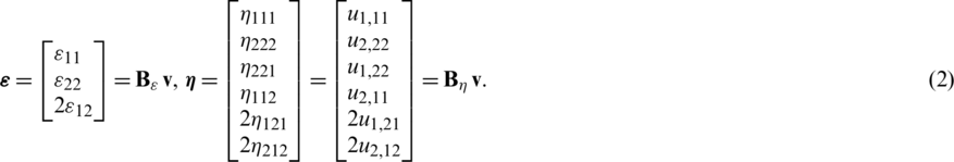
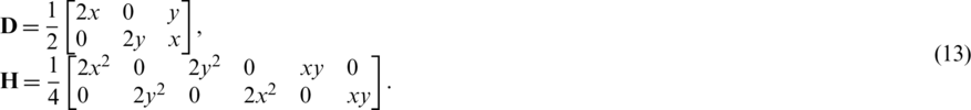
which builds the constitutive relations at the macrolevel, where the incremental stress and double stress are expressed as:
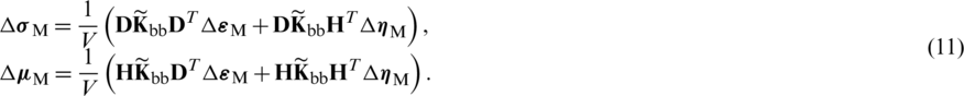
Eq. (11) yields the constitutive matrices in the following form
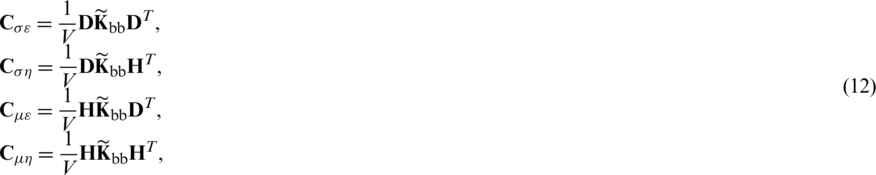
where D and H are the coordinate matrices [37] containing the Cartesian coordinates of the all boundary MVE nodes
Since  depends on the D and l,
  , it is easy to conclude that the macrostructural constitutive matrices are function of damage variable, and on this way, the microstructural damage is upscaled at the macrolevel.
All formulations, presented and expressed by the relevant element matrices, have been implemented into the FE software ABAQUS via user subroutine UEL [39]. It is to note that the undesired phenomenon such as volumetric locking in elastoplastic analysis does not appear because of mixed quadrilateral element formulation and a high interpolation polynomial in C1 element formulation as well.
4 Scale Transition Methodology
As known in multiscale schemes, boundary value problems of multiple scales (at least two) are solved simultaneously. In this paper, the two scales are considered, where the MVE is associated to every material point at the macroscale. At the microlevel, the classical local theory concept is preserved, which governs macroscale material response, where the nonlocal continuum theory is employed. Since a single macrolevel material point is now replaced by a small part of the microstructure, all macroscale state variables are expressed as an average of the corresponding microscale values. The computational scheme of two-scale algorithm is presented in Fig. 2. As evident, all multiscale simulations are run in online fashion, i.e., during the macroscale simulation. Using the macrolevel displacement increment  , the displacement gradients
  and
and  are calculated. From those displacement gradients, the increment of displacement field
  is expressed

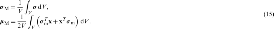
which is imposed over the MVE boundaries obeying the periodic boundary conditions. For the classical second-order homogenization, the averaging of Cauchy stress  and double stress
  are performed over the complete MVE, where the well-known Hill–Mandel condition is used. Accordingly, the homogenized stress and double stress tensors are computed and may be written as:
The homogenized constitutive response is obtained by performing the static condensation procedure over the whole MVE as shown above.

Figure 2: Computational scheme of the two-scale algorithm
As written in the previous section, the averaged quantities computed at the microstructural level are expressed in terms of the damage variable, describing the softening response. It means, with the development of the localization zone on the MVE, the homogenized stress tensors and constitutive behaviour experience decrease in their values, leading to the softening at the macroscale. Considering the localized character of damage evolution, it is evident that the averaging performed in the classical homogenization manner overestimates material response. For mild damage this issue is not so apparent, but for high localization the homogenization through the complete MVE leads to the overstiff behaviour. As known in the standard homogenization, the damage variable can appear only at the microscale, contributing to the overall average material response. It means, all state variables, computed at the microlevel and upscaled using averaging procedure to the macrolevel, are expressed in terms of damage. To avoid the overestimation, a controlling parameter at the macroscale, expressed by the homogenized damage variable, is proposed. Accordingly, when the homogenized damage reaches some appropriately chosen critical value, the corresponding macrolevel material point should be excluded from subsequent computation by setting its stiffness to small magnitude, but sufficiently large to preserve numerical stability. As explained in [27], to obtain realistic homogenized material behaviour during softening, the computation of the homogenized variables should be conducted only in the MVE material points within the localization zone. The procedure for determination of the localization zone at microscale has been derived and verified in [35]. The proposed method relies on the computation of the local equivalent strain  through the MVE area during loading history. The equivalent strain is taken according to [1], and it is defined as:

Herein,  ,
,  and
and  denote the principal strains. Since the plane strain is considered,
  is set to zero. On the onset of softening, the highest equivalent strain
  is usually occurred in the localization band. However, only a single material point exhibits maximum value of equivalent strain. To capture a set of material points which form the localization band, the following threshold criterion based on the equivalent strain is introduced

This expression is used in order to make distinction whether the particular MVE material point is inside  or outside
  the localization zone. In that way, the threshold parameter
  controls the width of the band, where the homogenization of damage is performed. The verification of the proposed methodology has been thoroughly discussed in [35], where it has been concluded that setting threshold parameter
  to 0.3 captures the microstructural localization band and ensures that averaged value of the damage determined within the band rises up to the failure. Besides the criterion (17), to ensure that the MVE localization band is precisely captured, an additional criterion is used which is defined in terms of the microstructural damage variable
  . Namely, the MVE localization band consists of the material points which should satisfy the criterion (17) and the increase in damage is exhibited,

In this way, the material points associated with unloading are excluded from consideration. Therefore, the MVE material points which obey conditions (17) and (18) form the localization area  , where the controlling parameter D is evaluated using an averaging procedure,

In the numerical examples considered in this paper, the macrolevel points in which the controlling parameter D reaches value 0.95 are excluded from subsequent computations.
5.1 Homogeneous Strip Subjected to Tensile Loading
The algorithm presented above is firstly tested by computing a simple homogeneous strip subjected to tensile loading, as shown in Fig. 3. As evident, a weakened zone with lower yield stress is placed in the middle of the strip in order to initiate softening.

Figure 3: Macrolevel strip
Accordingly, a “homogeneous MVE” is considered which is discretized by the 4 mixed quadrilateral finite elements, as shown in Fig. 4, employing the softening algorithm.

Figure 4: “MVE” of a homogeneous material
The MVE side length is L = 0.5 mm. The elastic properties of material are Young’s modulus 210 GPa and Poisson’s ratio 0.3. The material exhibits linear isotropic hardening at the yield stress of  with the hardening modulus of
  . The softening is described by the damage evolution law expressed in (4) with the microstructural parameter
  and softening exponent
  . The yield stress of
  is used in the weakened zone.
Here the results obtained by the present algorithm employing C1 triangular finite element and second-order homogenization are compared with the approach using the first-order homogenization procedure, where the macrolevel discretization is performed by the standard C0 finite element CPE8R with eight nodes used form Abaqus element library. The first-order homogenization can be found in many references [24,40] and it is also applied in the authors publication [24]. Therein, only the Cauchy stress tensor and the corresponding strain are used. It means, the classical continuum theory has been applied at macrolevel instead of the nonlocal theory considered in this paper.
Both the discretization with 70 triangular labelled as C1PE3 and the discretization with 90 quadrilateral elements CPE8R are presented in Fig. 5. The C1 computational model consists of 576 DOF, while the model with quadrilateral elements has 618 DOF. To enforce the straight left and right edges, an appropriate boundary conditions are applied, as described in [19].

Figure 5: Discretizations of the strip: (a) C1 triangular finite elements, (b) C0 quadrilateral finite elements
The macrolevel deformation response of the strip is displayed in Fig. 6 for both homogenization schemes. As evident, the second-order homogenization using C1 triangular finite elements exhibits the realistic softening behaviour, which can be confirmed by comparison with the results obtained using other methods in the available literature [41–43]. After reaching the peak point, continuous unloading appears, as expected. The homogenized damage distribution at macrolevel is presented in Fig. 7. On contrary, the nonphysical post peak behaviour is obtained when the first-order homogenization and the quadrilateral finite element mesh are used. The unrealistic spurious local hardening response is displayed, which is demonstrated by the increase in the macrolevel force in the post-peak behaviour. This is also associated with an unrealistic softening distribution.

Figure 6: Macrolevel force-displacement diagram
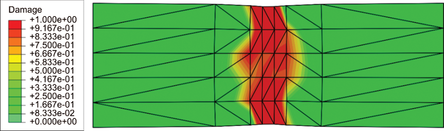
Figure 7: Distribution of homogenized damage
Therein, it is shown that the second-order homogenization, based on the nonlocal continuum theory at the macrolevel, gives a realistic softening behaviour even though the standard averaging procedure over only one MVE is used in the microlevel homogenization approach displayed in Fig. 2. According to the analysis performed in [36], it is expected that the finite element discretisation does not affect the results. A thoroughly mesh dependency examination is out of scope of this paper. In the following computation, some benchmark examples dealing with ductile damage of heterogeneous materials are considered.
5.2 Heterogeneous Strip Subjected to Tensile Loading
As the second example, the strip under tensile loading is again considered, but a heterogeneous material is here used. The geometry of the macromodel is presented in Fig. 3. To reduce the computational cost the number of elements is decreased in the computational model. The macrostructural discretization is performed by 42 triangular finite elements using the mesh shown in Fig. 8, and the boundary conditions are the same as in the previous example. The MVE is shown in Fig. 9.

Figure 8: Triangular finite element mesh
The material of the MVE is an academic porous steel with the unchanged material parameters. The microstructural parameter is set to  , and the damage exponent is
  . The MVE side length is
  , and it consists of 13% of voids with the average radius of 0.043 mm. The discretization is performed by 508 finite elements using the mesh as presented in Fig. 9.

Figure 9: RVE of heterogeneous ductile steel
The macrolevel deformation response presented by the load-displacement diagram is displayed in Fig. 10.

Figure 10: Force-displacement diagram of the strip subjected to tensile loading
As observed, after increasing of macrolevel force and reaching the peak point, the softening is exhibited which is in accordance with the solutions in previous example considering homogeneous material. Due to the porosities acting as strain concentrators, where the damage initiates and spreads through the MVE, here very fast softening occurs. It could be considered as physically correct. Unfortunately, the results cannot be compared to results from literature, because it is not possible to find the same academic MVE. An experimental study is possible, but it is out of scope of this contribution. Figs. 11 and 12 present the distribution of damage variable at the micro- and macrolevel at loading stage I, where the macrolevel softening is initiated and the loading stage II at the structural collapse, as labelled in Fig. 10.

Figure 11: Damage distribution at micro- and macrolevel for the loading stage I in Fig. 10

Figure 12: Damage distribution at micro- and macrolevel for the loading stage II in Fig. 10
According to the boundary conditions, the softening is concentrated over the weakened zone and slightly spreads to other parts of the structure, as expected. The MVEs appointed to the points A and B in Figs. 11 and 12 have very similar mechanical response, but the point A demonstrates a slightly stronger softening, which is additionally confirmed by the homogenized damage distribution at the macromodel. Very similar mechanical response of the strip has been found in [35] by utilization of the multiple homogenization. However, the numerical values cannot be compared due to the differences in material properties and boundary conditions.
5.3 Plate Subjected to Compressive Loading
The last example in the paper is again the standard benchmark problem of a plate subjected to compression expressed by the displacement v. This problem is usually used for testing accuracy and numerical efficiency of algorithms proposed and may be found in extensive literature [6,44,45]. The macrolevel model with discretization by 70 triangular elements is shown in Fig. 13. The bottom and top edge of the plate have boundary conditions ensuring straight edge. The plate geometry parameter is set to  . The middle plate zone with dimensions
  has decreased yield stress in order to initiate softening response. The material used is the same as in the previous problem. The MVE is presented in Fig. 9 with the unchanged material parameters.

Figure 13: Plate subjected to compression
The force-displacement diagram presenting softening response is shown in Fig. 14, where the loading levels I and II are again marked.

Figure 14: Force-displacement diagram of the plate boundaries subjected to compression
In comparison to the thin strip deformation response displayed in the previous sections, the softening in this problem is developing slightly slower. Although the material is identical in both examples, difference in the slope of the curve during the softening can be explained by the fact that in the previous example the weakened zone is spreading through entire cross-section of the macromodel. However, in this particular problem, the weakness is initiated only in a small portion of the model, and thereafter the localization propagates towards the opposite boundary. The spreading of the softening at the microscale as well as the distribution of the homogenized damage at the macrolevel for the loading stages I and II are displayed in Figs. 15 and 16.

Figure 15: Damage distribution at micro- and macrolevel for the loading stage I in Fig. 14

Figure 16: Damage distribution at micro- and macrolevel for the loading stage II in Fig. 14
As evident, the realistic behaviour has been again obtained. The physical consistency is additionally confirmed by plotting the damage contours over the MVEs assigned to the material points A, B and C on the macromodel. The macroscale localization firstly initiates at the point A and propagates to the points B and C. The comparison of the results obtained here with the softening responses of the same sample presented in the authors’ work [35], where the multiple homogenization has been used at the microlevel, can also prove accuracy of the newly proposed computational procedure. It is known that computational homogenization scheme is time demanding, as a consequence of the “online” microscale computations in every macrolevel material point. The simulations within this paper were performed on a workstation with 8 cores and clock rate 2 GHz. The numerical examples performed on the homogeneous material and presented in this paper were completed in two days. The examples comprising heterogeneous material were finished in approximately five days. Improvement of the numerical efficiency is clearly needed, through parallelization and speeding of the micro-macro scale transition procedure, as well. In the code developed by the authors, speedup of the performance was accomplished at the macrolevel, where all material points within single macrolevel element were computed in parallel. The authors’ further research is concerned with the development of much more efficient homogenization procedures using clustering approaches [46,47].
The paper demonstrates ability of the second-order homogenization procedure to model ductile damage responses in heterogeneous materials. Accordingly, the C1 continuity finite element discretization employing the nonlocal continuum theory has been performed at the macrolevel. The softening behaviour is modelled at the microlevel using the implicit gradient-enhanced elastoplasticity, where the damage evolution is expressed in terms of the nonlocal equivalent plastic strain which is an additional nodal variable in the mixed quadrilateral finite element formulation applied.
The homogenization governed by the displacement gradient variables and the regularization employing the gradient-enhanced elastoplasticity, where averaging over only one microstructural volume element has been performed, yields the physically realistic softening responses at the macrolevel. However, if the C0 continuity displacement based finite element discretization at macrolevel is applied, which is associated with the first-order homogenization, the unrealistic results are obtained.
To overwhelm the well-known problem of overestimating homogenized behaviour in softened materials when standard averaging scheme is employed, the homogenized damage variable computed within the MVE localization zone is used as the controlling parameter. In addition, the macrolevel softening is governed by the microlevel damage variable and the threshold criterion based on the local equivalent strain. The physically realistic damage responses of the MVE expressing by the localization bands are computed, which are connected with the realistic macrolevel softening behaviour, as expected. The results obtained compare very good with the solutions obtained in the previous authors’ work, where the more complicate multiple homogenization at the microlevel has been used.
Funding Statement: The authors received no specific funding for this study.
Conflicts of Interest: The authors declare that they have no conflicts of interest to report regarding the present study.
1. Mazars, J., Pijaudier-Cabot, G. (1989). Continuum damage theory: Application to concrete. Journal of Engineering Mechanics, 115(2), 345–365. DOI 10.1061/(ASCE)0733-9399(1989)115:2(345). [Google Scholar] [CrossRef]
2. Sánchez, P. J., Blanco, P. J., Huespe, A. E., Feijóo, R. A. (2013). Failure-oriented multi-scale variational formulation: Micro-structures with nucleation and evolution of softening bands. Computer Methods in Applied Mechanics and Engineering, 257, 221–247. DOI 10.1016/j.cma.2012.11.016. [Google Scholar] [CrossRef]
3. Coenen, E. W. C., Kouznetsova, V. G., Geers, M. G. D. (2012). Multi-scale continuous-discontinuous framework for computational-homogenization-localization. Journal of the Mechanics and Physics of Solids, 60(8), 1486–1507. DOI 10.1016/j.jmps.2012.04.002. [Google Scholar] [CrossRef]
4. Roters, F., Eisenlohr, P., Hantcherli, L., Tjahjanto, D. D., Bieler, T. R. et al. (2010). Overview of constitutive laws, kinematics, homogenization and multiscale methods in crystal plasticity finite-element modeling: Theory, experiments, applications. Acta Materialia, 58(4), 1152–1211. DOI 10.1016/j.actamat.2009.10.058. [Google Scholar] [CrossRef]
5. Peerlings, R. H. J., De Borst, R., Brekelmans, W. A. M., De Vree, J. H. P. (1996). Gradient enhanced damage for quasi-brittle materials. International Journal for Numerical Methods in Engineering, 39(19), 3391–3403. DOI 10.1002/(SICI)1097-0207(19961015)39:19¡3391::AID-NME7¿3.0.CO;2-D. [Google Scholar] [CrossRef]
6. Engelen, R. A. B., Geers, M. G. D., Baaijens, F. P. T. (2003). Nonlocal implicit gradient-enhanced elasto-plasticity for the modelling of softening behaviour. International Journal of Plasticity, 19(4), 403–433. DOI 10.1016/S0749-6419(01)00042-0. [Google Scholar] [CrossRef]
7. Seleš, K., Lesičar, T., Tonković, Z., Sorić, J. (2019). A residual control staggered solution scheme for the phase-field modeling of brittle fracture. Engineering Fracture Mechanics, 205, 370–386. DOI 10.1016/j.engfracmech.2018.09.027. [Google Scholar] [CrossRef]
8. Ambati, M., Gerasimov, T., De Lorenzis, L. (2015). A review on phase-field models of brittle fracture and a new fast hybrid formulation. Computational Mechanics, 55(2), 383–405. DOI 10.1007/s00466-014-1109-y. [Google Scholar] [CrossRef]
9. Borden, M. J., Hughes, T. J. R., Landis, C. M., Anvari, A., Lee, I. J. (2018). Phase-field formulation for ductile fracture BT. In: Oñate, E., Peric, D., de Souza Neto, E., Chiumenti, M. (Eds.Advances in computational plasticity: A book in honour of D. Roger J. Owen. pp. 45–70. New York: Springer International Publishing. [Google Scholar]
10. de Borst, R., Verhoosel, C. V. (2016). Gradient damage vs. phase-field approaches for fracture: Similarities and differences. Computer Methods in Applied Mechanics and Engineering, 312, 78–94. DOI 10.1016/j.cma.2016.05.015. [Google Scholar] [CrossRef]
11. Geers, M. G. D., Kouznetsova, V. G., Brekelmans, W. A. M. (2010). Multi-scale computational homogenization: Trends and challenges. Journal of Computational and Applied Mathematics, 234(7), 2175–2182. DOI 10.1016/j.cam.2009.08.077. [Google Scholar] [CrossRef]
12. Matouš, K., Geers, M. G. D., Kouznetsova, V. G., Gillman, A. (2017). A review of predictive nonlinear theories for multiscale modeling of heterogeneous materials. Journal of Computational Physics, 330, 192–220. DOI 10.1016/j.jcp.2016.10.070. [Google Scholar] [CrossRef]
13. Forest, S. (2002). Homogenization methods and mechanics of generalized continua-Part 2. Theoretical and Applied Mechanics, (28–29), 113–114. DOI 10.2298/TAM0229113F. [Google Scholar] [CrossRef]
14. Michel, J. C., Suquet, P. (2003). Nonuniform transformation field analysis. International Journal of Solids and Structures, 40(25), 6937–6955. DOI 10.1016/S0020-7683(03)00346-9. [Google Scholar] [CrossRef]
15. Oskay, C., Fish, J. (2007). Eigendeformation-based reduced order homogenization for failure analysis of heterogeneous materials. Computer Methods in Applied Mechanics and Engineering, 196(7), 1216–1243. DOI 10.1016/j.cma.2006.08.015. [Google Scholar] [CrossRef]
16. Perić, D., de Souza Neto, E. A., Feijóo, R. A., Partovi, M., Molina, A. J. C. (2011). On micro-to-macro transitions for multi-scale analysis of non-linear heterogeneous materials: Unified variational basis and finite element implementation. International Journal for Numerical Methods in Engineering, 87(1–5), 149–170. DOI 10.1002/nme.3014. [Google Scholar] [CrossRef]
17. Luscher, D. J., McDowell, D. L., Bronkhorst, C. A. (2010). A second gradient theoretical framework for hierarchical multiscale modeling of materials. International Journal of Plasticity, 26(8), 1248–1275. DOI 10.1016/j.ijplas.2010.05.006. [Google Scholar] [CrossRef]
18. Kaczmarczyk, L. K., Pearce, C. J., Bicanic, N. (2008). Scale transition and enforcement of RVE boundary conditions in second-order computational homogenization. International Journal for Numerical Methods in Engineering, 74(3), 506–522. DOI 10.1002/nme.2188. [Google Scholar] [CrossRef]
19. Lesičar, T., Tonković, Z., Sorić, J. (2017). Two-scale computational approach using strain gradient theory at microlevel. International Journal of Mechanical Sciences, 126, 67–78. DOI 10.1016/j.ijmecsci.2017.02.017. [Google Scholar] [CrossRef]
20. Mindlin, R. D. (1964). Micro-structure in linear elasticity. Archive for Rational Mechanics and Analysis, 16(1), 51–78. DOI 10.1007/BF00248490. [Google Scholar] [CrossRef]
21. Mindlin, R. D. (1965). Second gradient of strain and surface-tension in linear elasticity. International Journal of Solids and Structures, 1(4), 417–438. DOI 10.1016/0020-7683(65)90006-5. [Google Scholar] [CrossRef]
22. Putar, F., Sorić, J., Lesičar, T., Tonković, Z. (2017). Damage modeling employing strain gradient continuum theory. International Journal of Solids and Structures, 120, 171–185. DOI 10.1016/j.ijsolstr.2017.04.039. [Google Scholar] [CrossRef]
23. Hettich, T., Hund, A., Ramm, E. (2008). Modeling of failure in composites by X-FEM and level sets within a multiscale framework. Computer Methods in Applied Mechanics and Engineering, 197(5), 414–424. DOI 10.1016/j.cma.2007.07.017. [Google Scholar] [CrossRef]
24. Miehe, C. (2003). Computational micro-to-macro transitions for discretized micro-structures of heterogeneous materials at finite strains based on the minimization of averaged incremental energy. Computer Methods in Applied Mechanics and Engineering, 192(5–6), 559–591. DOI 10.1016/S0045-7825(02)00564-9. [Google Scholar] [CrossRef]
25. Brekelmans, W. A. M., Geers, M. G. D., Kouznetsova, V. G. (2009). Computational homogenisation for non-linear heterogeneous solids, in multiscale model. In: Galvanetto, U., Aliabadi, M. F. H. (Eds.Multiscale model, pp. 1–42. London: Imperial College Press. [Google Scholar]
26. Coenen, E. W. C., Kouznetsova, V. G., Geers, M. G. D. (2011). Enabling microstructure-based damage and localization analyses and upscaling. Modelling and Simulation in Materials Science and Engineering, 19(7), 74008. DOI 10.1088/0965-0393/19/7/074008. [Google Scholar] [CrossRef]
27. Phu Nguyen, V., Lloberas-Valls, O., Stroeven, M., Johannes Sluys, L. (2010). On the existence of representative volumes for softening quasi-brittle materials: A failure zone averaging scheme. Computer Methods in Applied Mechanics and Engineering, 199(45–48), 3028–3038. DOI 10.1016/j.cma.2010.06.018. [Google Scholar] [CrossRef]
28. Loehnert, S., Belytschko, T. (2007). A multiscale projection method for macro/microcrack simulations. International Journal for Numerical Methods in Engineering, 71(12), 1466–1482. DOI 10.1002/nme.2001. [Google Scholar] [CrossRef]
29. Guidault, P. A., Allix, O., Champaney, L., Cornuault, C. (2008). A multiscale extended finite element method for crack propagation. Computer Methods in Applied Mechanics and Engineering, 197(5), 381–399. DOI 10.1016/j.cma.2007.07.023. [Google Scholar] [CrossRef]
30. Nguyen, V. P., Lloberas-Valls, O., Stroeven, M., Sluys, L. J. (2011). Homogenization-based multiscale crack modelling: From micro-diffusive damage to macro-cracks. Computer Methods in Applied Mechanics and Engineering, 200(9–12), 1220–1236. DOI 10.1016/j.cma.2010.10.013. [Google Scholar] [CrossRef]
31. Benedetti, I., Aliabadi, M. H. (2015). Multiscale modeling of polycrystalline materials: A boundary element approach to material degradation and fracture. Computer Methods in Applied Mechanics and Engineering, 289, 429–453. DOI 10.1016/j.cma.2015.02.018. [Google Scholar] [CrossRef]
32. Tchalla, A., Azoti, W. L., Koutsawa, Y., Makradi, A., Belouettar, S. et al. (2015). Incremental mean-fields micromechanics scheme for non-linear response of ductile damaged composite materials. Composites Part B: Engineering, 69, 169–180. DOI 10.1016/j.compositesb.2014.08.055. [Google Scholar] [CrossRef]
33. Fernandino, D. O., Cisilino, A. P., Toro, S., Sanchez, P. J. (2017). Multi-scale analysis of the early damage mechanics of ferritized ductile iron. International Journal of Fracture, 207(1), 1–26. DOI 10.1007/s10704-017-0215-1. [Google Scholar] [CrossRef]
34. Ibrahimbegović, A., Markovič, D. (2003). Strong coupling methods in multi-phase and multi-scale modeling of inelastic behavior of heterogeneous structures. Computer Methods in Applied Mechanics and Engineering, 192(28–30), 3089–3107. DOI 10.1016/S0045-7825(03)00342-6. [Google Scholar] [CrossRef]
35. Lesičar, T., Sorić, J., Tonković, Z. (2019). Ductile damage modelling of heterogeneous materials using a two-scale computational approach. Computer Methods in Applied Mechanics and Engineering, 355, 113–134. DOI 10.1016/j.cma.2019.06.013. [Google Scholar] [CrossRef]
36. Putar, F., Sorić, J., Lesičar, T., Tonković, Z. (2019). A multiscale method for damage analysis of quasi-brittle heterogeneous materials. Computer Modeling in Engineering & Sciences, 200(1), 123–156. DOI 10.32604/cmes.2019.06562. [Google Scholar] [CrossRef]
37. Lesičar, T., Tonković, Z., Sorić, J. (2014). A second-order two-scale homogenization procedure using C1 macrolevel discretization. Computational Mechanics, 54(2), 425–441. DOI 10.1007/s00466-014-0995-3. [Google Scholar] [CrossRef]
38. Lesičar, T., Sorić, J., Tonković, Z. (2016). Large strain, two-scale computational approach using C1 continuity finite element employing a second gradient theory. Computer Methods in Applied Mechanics and Engineering, 298, 303–324. DOI 10.1016/j.cma.2015.09.017. [Google Scholar] [CrossRef]
39. Smith, M. (2014). ABAQUS/Standard user’s manual, Version 6.14. Providence. RI: Dassault Systèmes Simulia Corp. [Google Scholar]
40. Kouznetsova, V., Brekelmans, W. A. M., Baaijens, F. P. T. (2001). An approach to micro-macro modeling of heterogeneous materials. Computational Mechanics, 27(1), 37–48. DOI 10.1007/s004660000212. [Google Scholar] [CrossRef]
41. Yang, Y., Misra, A. (2010). Higher-order stress-strain theory for damage modeling implemented in an element-free galerkin formulation. Computer Modeling in Engineering & Sciences, 64(1), 1–36. DOI 10.3970/cmes.2010.064.001. [Google Scholar] [CrossRef]
42. Geers, M. G. D. (2004). Finite strain logarithmic hyperelasto-plasticity with softening: A strongly non-local implicit gradient framework. Computer Methods in Applied Mechanics and Engineering, 193(30–32), 3377–3401. DOI 10.1016/j.cma.2003.07.014. [Google Scholar] [CrossRef]
43. Geers, M. G. D., Ubachs, R. L. J. M., Engelen, R. A. B. (2003). Strongly non-local gradient-enhanced finite strain elastoplasticity. International Journal for Numerical Methods in Engineering, 56(14), 2039–2068. DOI 10.1002/nme.654. [Google Scholar] [CrossRef]
44. Simone, A., Askes, H., Sluys, L. J. (2004). Incorrect initiation and propagation of failure in non-local and gradient-enhanced media. International Journal of Solids and Structures, 41(2), 351–363. DOI 10.1016/j.ijsolstr.2003.09.020. [Google Scholar] [CrossRef]
45. Poh, L. H., Sun, G. (2017). Localizing gradient damage model with decreasing interactions. International Journal for Numerical Methods in Engineering, 110(6), 503–522. DOI 10.1002/nme.5364. [Google Scholar] [CrossRef]
46. Liu, Z., Bessa, M. A., Liu, W. K. (2016). Self-consistent clustering analysis: An efficient multi-scale scheme for inelastic heterogeneous materials. Computer Methods in Applied Mechanics and Engineering, 306, 319–341. DOI 10.1016/j.cma.2016.04.004. [Google Scholar] [CrossRef]
47. Zhang, L., Tang, S., Yu, C., Zhu, X., Liu, W. K. (2019). Fast calculation of interaction tensors in clustering-based homogenization. Computational Mechanics, 64(2), 351–364. DOI 10.1007/s00466-019-01719-x. [Google Scholar] [CrossRef]
 | This work is licensed under a Creative Commons Attribution 4.0 International License, which permits unrestricted use, distribution, and reproduction in any medium, provided the original work is properly cited. |