| Computer Modeling in Engineering & Sciences |
DOI: 10.32604/cmes.2021.015208
ARTICLE
Numerical Analysis of Three-Layer Deep Tunnel Composite Structure
1Hubei Key Laboratory of Theory and Application of Advanced Materials Mechanics, School of Science, Wuhan University of Technology, Wuhan, 430070, China
2China Construction Third Bureau Green Industry Investment Co., Ltd., Wuhan, 430035, China
3Fujian Lutong Pipe Technology Co., Ltd., Quanzhou, 362000, China
*Corresponding Author: Jianzhong Chen. Email: cjzwhut@163.com
Received: 01 December 2020; Accepted: 28 December 2020
Abstract: To date, with the increasing attention of countries to urban drainage system, more and more regions around the world have begun to build water conveyance tunnels, sewage pressure deep tunnels and so on. However, the sufficient bearing capacity and corrosion resistance of the structure, which can ensure the actual service life and safety of the tunnel, remain to be further improved. Glass Fiber Reinforced Plastics (GFRP) pipe, with light weight, high strength and corrosion resistance, has the potential to be applied to the deep tunnel structure. This paper proposed a new composite structure of deep tunnel lined with GFRP pipe, which consisted of three layers of concrete segment, cement paste and GFRP pipe. A new pipe-soil spring element model was proposed for the pipe-soil interaction with gaps. Based on the C3D8R solid model and the Combin39 spring model, the finite element numerical analysis of the internal pressure status and external pressure stability of the structure was carried out. Combined with the checking calculation of the theoretical formula, the reliability of the two finite element models was confirmed. A set of numerical analysis methods for the design and optimization of the three-layer structure was established. The results showed that from the internal GFRP pipe to the outer concrete pipe, the pressure decreased from 0.5 to 0.32 MPa, due to the internal pressure was mainly undertaken by the inner GFRP pipe. The allowable buckling pressure of GFRP pipe under the cover of 5 GPa high modulus cement paste was 2.66 MPa. The application of GFRP pipe not only improves the overall performance of the deep tunnel structure but also improves the construction quality and safety. The three-layer structure built in this work is safe and economical.
Keywords: GFRP pipe; deep tunnel structure; finite element analysis; internal pressure; external pressure stability; pipe-soil interaction
As the result of the current increasing engineering requirements and more complex geographical environment, the tunnel structure has been further investigated around the world. The optimization design of the tunnel structure is an important direction of continuous development, such as the Kanda Deep Tunnel, Tokyo “underground temple,” Kuala Lumpur Tunnel, Thames Sewage Tunnel, Yellow River Crossing Tunnel and so on [1–5]. In the structural scheme of Wuhan Great East Lake Deep Tunnel, multi-piece precast concrete segments were used as the external pressure bearing structure. In order to withstand the pressure of water delivery, avoid external groundwater leakage and internal water delivery corrosion, cast-in-place reinforced concrete was used as the secondary lining. However, there are some construction difficulties and quality risks in the implementation of this scheme, such as multiple procedures, long construction period, large risk of sealing and anti-corrosion in segmented pouring, which have certain influence on the reliability of sewage transportation. Glass Fiber Reinforced Plastics (GFRP) pipe, as a composite material pipe with light weight, high strength, corrosion resistance and excellent hydraulic properties, has been widely used in various industries such as municipal, marine, and nuclear power [6–8]. At present, this kind of pipe or material has been used in some major new tunnel lining or renovation projects, such as the Northern Sewerage Project (NSP)-the largest and most complex sewage tunnel project in Australian history, and the Northside Sewer Relief Tunnel (NSRT) in Houston [9,10]. The NSP project used DN1600-DN2500 GFRP pipes as the lining of the deep tunnel, with a length of 12.5 km and a design life of 100 years. In the NSRT project, approximately 8 miles of DN3000 GFRP pipes were used to refurbish the original HDPE lining that had fallen off due to corrosion.
The multi-layer composite structure has been applied more and more in engineering construction. Many existing methods of multi-layer structure analysis were based on the assumption of a through-the-thickness distribution of displacements, the derivation of strain and stress, and the application of virtual work principle. At present, more scholars use finite element method to establish the calculation model of composite laminar structure, most of which are based on the equivalent single-layer theory (ESL). From the classical laminated plate theory (CLPT) [11], the first-order shear deformation theory (FSDT) [12], to the higher-order shear deformation theory (HDST) [13], lateral deformation capability becomes more and more accurate with the increasing model complexity, but it is not sensitive to the single layer of laminated structure. Layer-wise theory can accurately describe the interlaminar stress and strain of composite laminated structures, but the calculation cost will increase as the number of layers [14].
The methods of pipe-soil interaction usually include contact surface method, PSI element method and spring element method. The contact surface method defines the contact of the pipe-soil solid model, which used to be the static analysis due to its large computational cost and difficulty in convergence during large deformation. Through the way that one side shares nodes with pipeline and other side represents the soil surface, PSI element comprehensively considers the contact surface property of the pipe-soil and the deformation characteristics of the soil, which simplifies the analysis process, but this element only has displacement freedom degree. The spring element method reflects constitutive relation of the soil by defining stiffness coefficient of the spring, which means that the soil around the pipe is discretized into springs distributed at a certain interval, without the need to establish the soil entity. Chen et al. [15] adopted the Link180 model to solve the problem between buried structure and surrounding soil, but it cannot simulate the special case of existing gap between the pipe and soil. Through the definition of the F-D value of the combin39 spring element, the pipe-soil interaction with gap required in this paper can be simulated. Kim et al. [16] conducted a finite element analysis on the structural performance of buried GFRP pipes, in which the Mohr–Coulomb failure criterion was adopted for soil conditions and linear elastic modeling was adopted for the beam element of GFRP pipe. Rafiee et al. [17] established a comprehensive model to evaluate the long-term creep of composite structures under constant load, and obtained the overall deformation and stress–strain distribution of the pipe through numerical calculations. Gherlone [18] performed a finite element analysis of the static response, free vibration and critical loads of the sandwich structure by using the mixed Refined Zigzag Theory model.
This paper proposed a three-layer deep tunnel composite structure lined with GFRP pipe, which was composed of concrete segment with high resistance to external pressure, GFRP pipe with high resistance to internal pressure and cement paste, as shown in Fig. 1. The application of GFRP pipe improves the overall performance of the tunnel structure. Compared with the traditional cast-in-place prestressed reinforced concrete, it simplifies the construction process of cast-in-place and thus greatly improves the quality and safety of construction. The outer layer of the actual structure is a rigid reinforced concrete segment with strong resistance to external pressure, and the construction of internal structure is carried out after the concrete segment construction has been completed for a period of time, the main load of inner lining is internal water pressure.
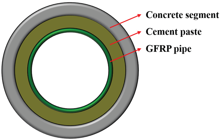
Figure 1: Schematic diagram of three-layer structure
Based on the finite element analysis of solid element model and the checking calculation of elastic mechanics theory formula, the basic characteristics of deep tunnel composite structure under internal pressure were analyzed. Based on the finite element analysis of the pipe-soil spring element model and the checking calculation of the buckling formula of M45 manual, this paper carried out research on the external pressure stability of the GFRP pipe with the gap between the soil and the pipe. The transfer law of internal pressure and strain from inside to outside and the allowable buckling pressure with gaps in tube-soil interaction were obtained to evaluate the safety and reliability of the structure and guide its structural design. The three-layer composite structure gives full play to the high external compressive strength of outer layer and high internal compressive strength of inner layer, which is a safe and economical structure.
3 Internal Hydraulic Analysis of Three-Layer Structure
3.1 Finite Element Analysis of Internal Hydraulic
In the analysis of pipe-soil interaction, the contact surface method is the most accurate solution, which can clearly see the stress distribution cloud diagram of the entire pipe and soil. In this paper, the contact surface method of solid elements was used to analyze the internal pressure of the three-layer structure. According to the structure size and material parameters of the deep tunnel composite structure lined with GFRP pipe, the finite element analysis model of the three-layer structure was established by ABAQUS finite element analysis software.
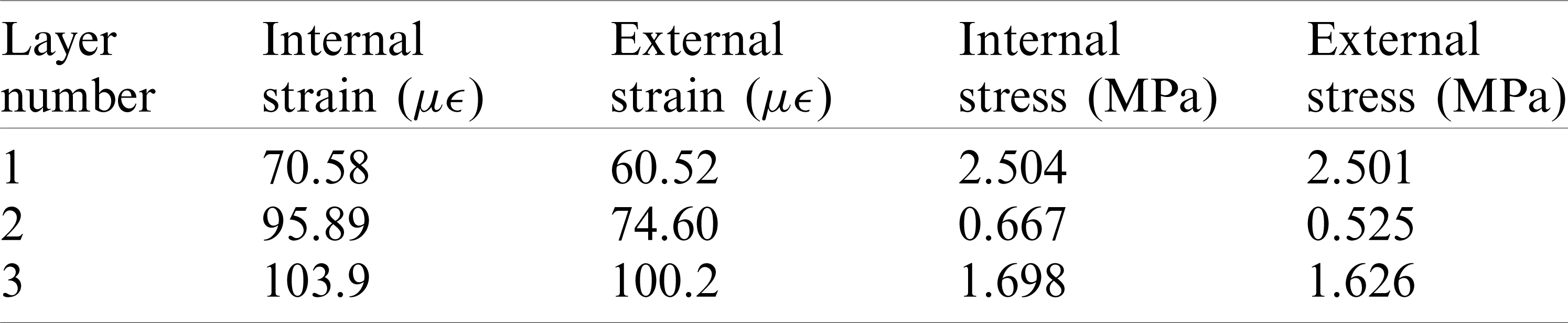
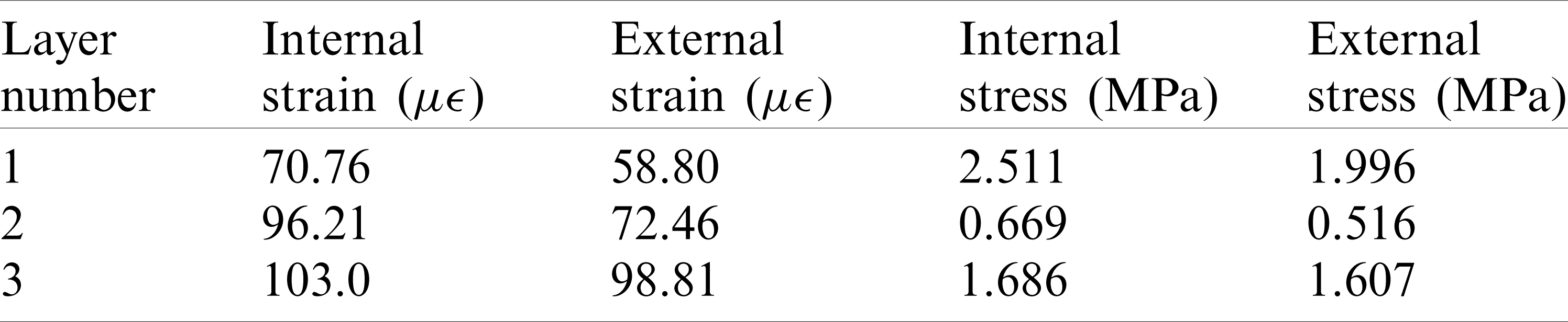
In ABAQUS, the types of solid elements based on stress-displacement are the most abundant. The 8-node hexahedral linear reduction integral element-C3D8R was adopted, and the contact pair properties of frictionless and hard surface contact were adopted. The calculation results of displacement by linear reduction integral element are more accurate, and the analysis accuracy will not be greatly affected when there is distortion or large deformation of mesh. The dimensions and material parameters of the three-layer structure were shown in Tab. 1. The finite element analysis model 1 was shown in Fig. 2. Constraint types were axial constraints on two end faces, x-direction constraints on the upper and lower sides, and y-direction constraints on the left and right sides. After applying the internal pressure of 0.5 MPa, the stress and strain of each layer were obtained, as shown in Figs. 3 and 4. The specific value of the stress–strain results was shown in Tab. 2.
Table 1: Dimensions and material parameters of three-layer structure
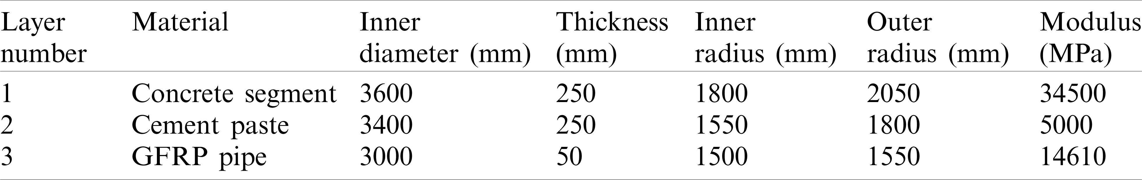
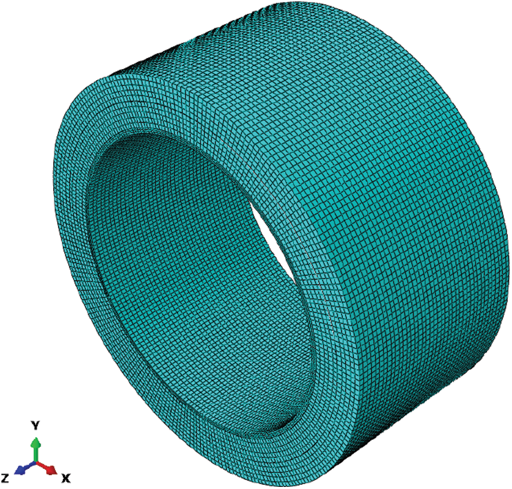
Figure 2: Finite element Model 1 for internal pressure analysis
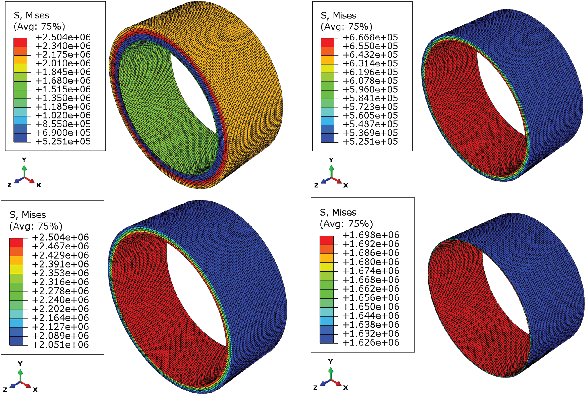
Figure 3: Stress results of three-layer structure
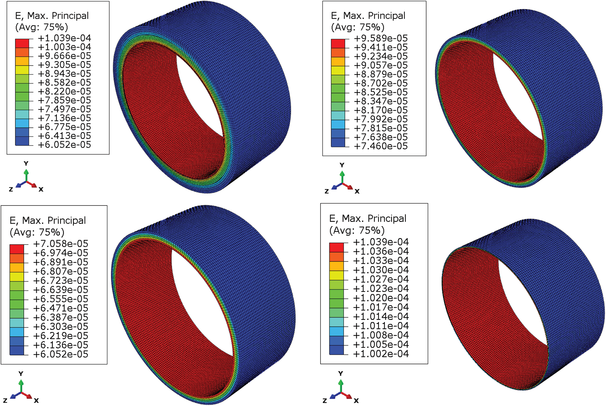
Figure 4: Strain results of three-layer structure
Table 2: The stress–strain results of finite element model 1
In this paper, another set of simulations was performed to verify the reliability of the above simplified constraints. The three-layer structure was embedded into the surrounding elastic medium, that was, solid elements of soil with modulus 15 MPa were established outside the three-layer structure. Internal pressure of 0.5 MPa was applied inside to observe its mechanical response. Also, there was only continuum mechanics, and there was no elastic mechanics. The finite element analysis model 2 was shown in Fig. 5. The constraint types were full constraints at the bottom and axial constraints at the two end faces. The stress–strain cloud diagram of Model 2 were obtained, as shown in Fig. 6. The stress–strain results of each layer obtained by Model 2 were basically consistent with model 1, as shown in Tab. 3.
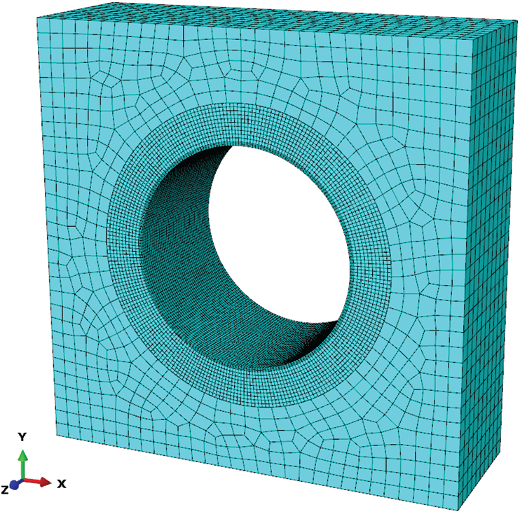
Figure 5: Finite element model 2 for internal pressure analysis
The material parameters of the three layers were shown in Tab. 1. The relevant data were substituted into the formula to calculate the stress and strain of each layer, and the theoretical calculation results were shown in Tab. 4.
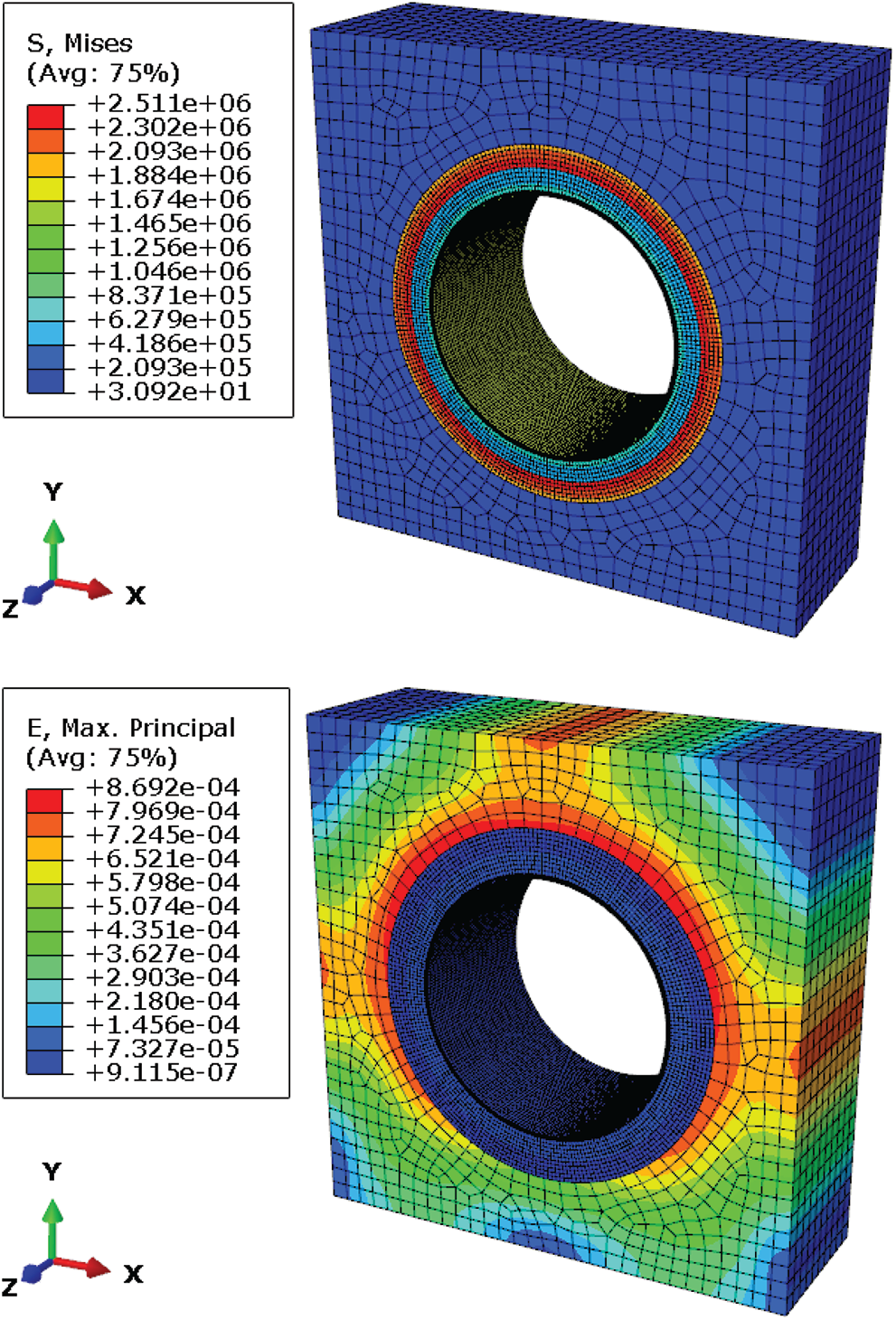
Figure 6: Stress–strain cloud diagram of Model 2
Table 3: The stress–strain results of Model 2
3.2 Theoretical Analysis Based on Elastic Mechanics
The three-layer structure proposed in this paper was composed of concrete segment, Cement paste and GFRP pipe. Under the action of internal pressure P, the pressure, stress and strain of each layer were deduced through elastic mechanics theory. The theoretical calculation model of three-layer structure was shown in Fig. 7.
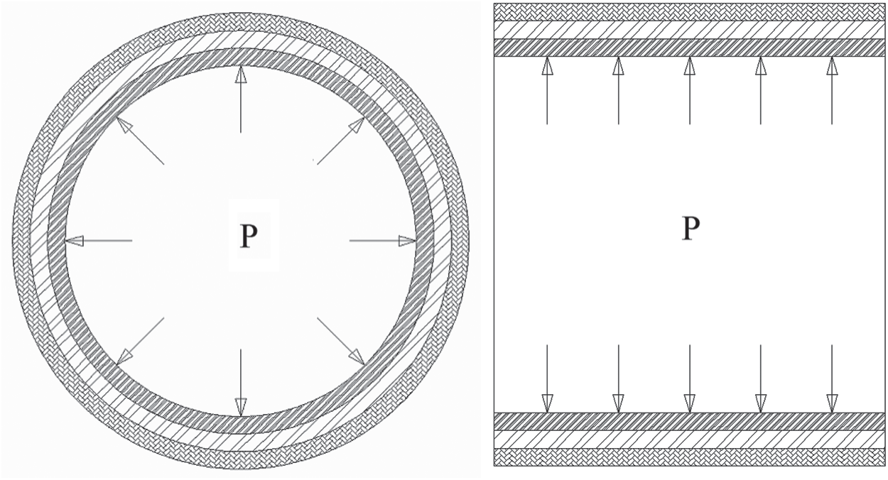
Figure 7: Theoretical calculation model of three-layer structure
For the convenience of analysis, the three-layer structure was divided into
where, Hi, Ii, Ji and Ki were the calculation coefficients set in this paper, which could be calculated according to the following formula:
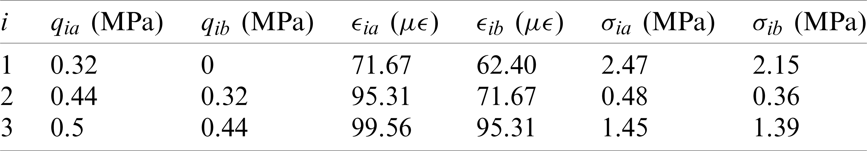
where, qia and qib were the internal pressure and external pressure of the ith layer respectively. When the internal pressure of innermost layer was P and the external pressure of outermost layer is 0, q3a was equal to P, q1b was equal to 0, q3b and q2b were calculated according to the following equation:
The basic characteristics of the three-layer structure under the action of internal pressure P were analyzed by numerical simulation of finite element and checking calculation of theoretical formula. According to the requirements of different materials, sizes and working conditions, we can continuously optimize the structural design through a set of numerical analysis methods established by solid element model and theoretical calculation formula. The stress–strain results of each layer obtained by finite element analysis and theoretical calculation are consistent, the external hoop strains of the concrete segments are 60.52 and 62.40
Table 4: Theoretical calculation results
4 External Pressure Stability Analysis of GFRP Pipe
4.1 Finite Element Analysis Based on Pipe-Soil Spring Element Model
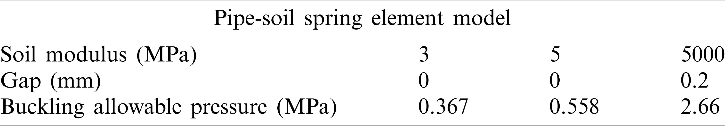
Considering the influence of water seepage in the outer structure, a new spring element model of pipe-soil interaction was proposed to analyze the external pressure stability of GFRP pipe, and the allowable buckling pressure with gaps was obtained. In the three-layer structure, GFRP pipe is surrounded by cast-in-place cement paste, which is equivalent to a high modulus soil cover, and does not need to consider the impact of buried depth and in-situ soil. There is often a gap between GFRP pipe and cement paste, its value varies with construction method and quality. In general, the construction gap can be 0.2 mm when the pipe is filled with compacted concrete and carefully grouted.
There are many elements that can be used to simulate springs in ANSYS finite element analysis software, and they have their unique applications in many aspects, such as link180, combin39, and combin40. The link180 element is defined by two nodes, cross-sectional area, mass per unit length, and material properties. It can simulate the soil around the pipe, but it cannot simulate the special case of existing gap between the pipe and soil. The combin39 spring element is a unidirectional element with nonlinear function, defined by two nodes and a generalized force-deformation curve, as shown in Fig. 8. In the structural analysis, the points (D1, F1, etc.) on the curve represent the relationship between force and translational displacement or the relationship between moment and rotational displacement. By the definition of real constants, force and deformation values of up to 20 points in the curve can be input. Through the definition of the F-D value of the combin39 spring element, the pipe-soil interaction with gap required in this paper can be simulated. The derivation formula of the stiffness coefficient k of combin39 is as follows:
where, E1 is the elastic modulus of the spring element (Pa), A is the cross-sectional area of the spring element (m2), L1 is the length of the spring element (m), Es is the elastic modulus of the soil around the pipe (Pa), and R is the radius of the pipe (m).
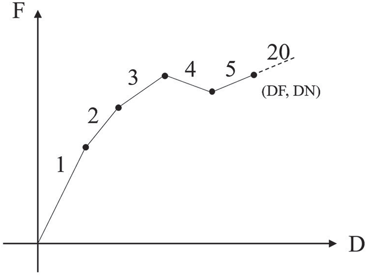
Figure 8: Generalized force-deformation curve
In the spring element model of pipe-soil interaction, GFRP pipe was established by shell63 element, and the combin39 element was established through the nodes on the surface to simulate the cement paste, as shown in Fig. 9. The constraints applied by the GFRP pipe were axial constraints on the middle plane, x-direction constraints on the upper and lower sides, and y-direction constraints on the left and right sides. Fixed constraints were applied to the ends of the spring elements. The constraint diagram was shown in Fig. 10. The external pressure of 1.0 MPa was applied to GFRP pipe, as shown in Fig. 11.
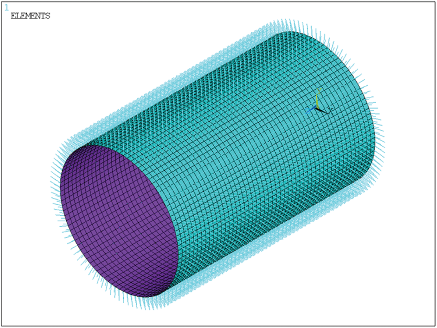
Figure 9: The spring element model of pipe-soil interaction
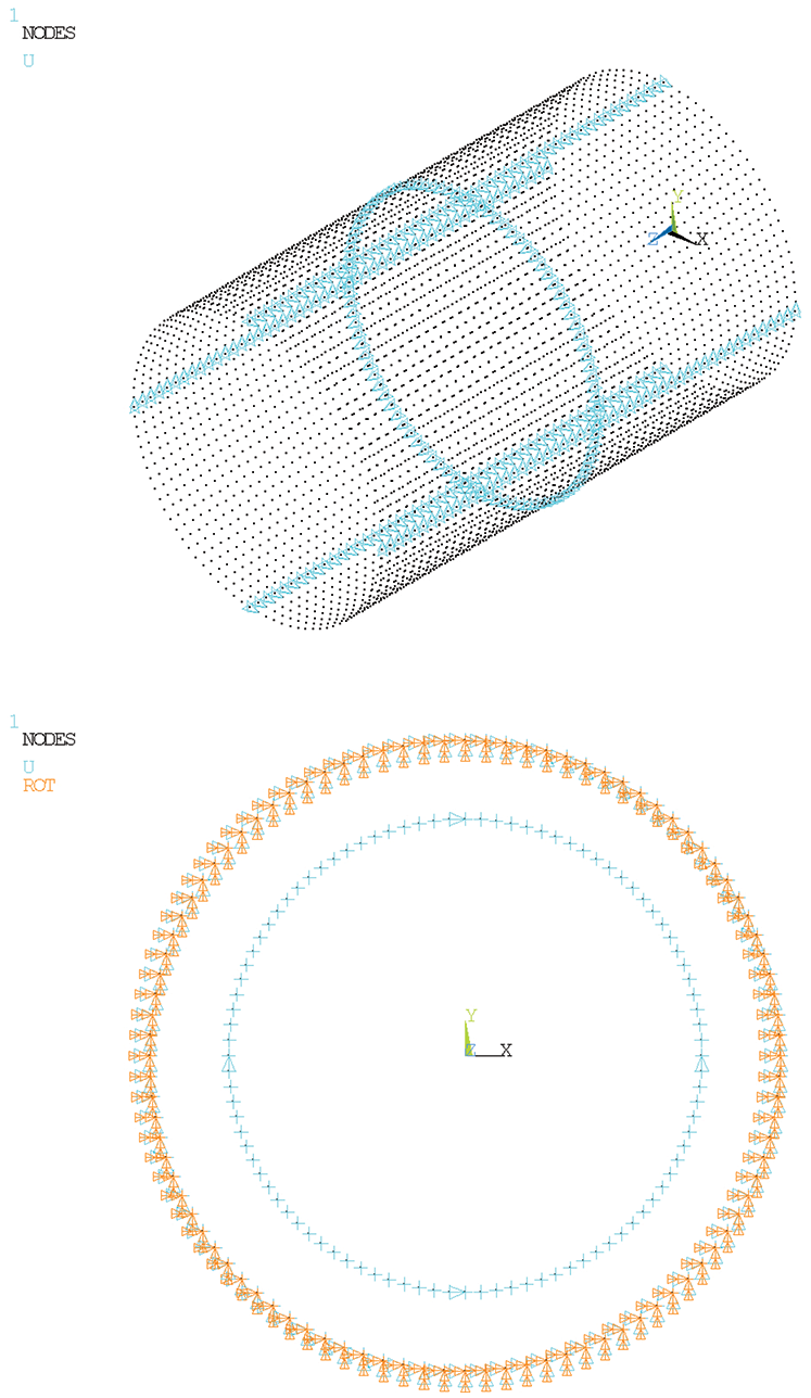
Figure 10: Constraint of the spring element model
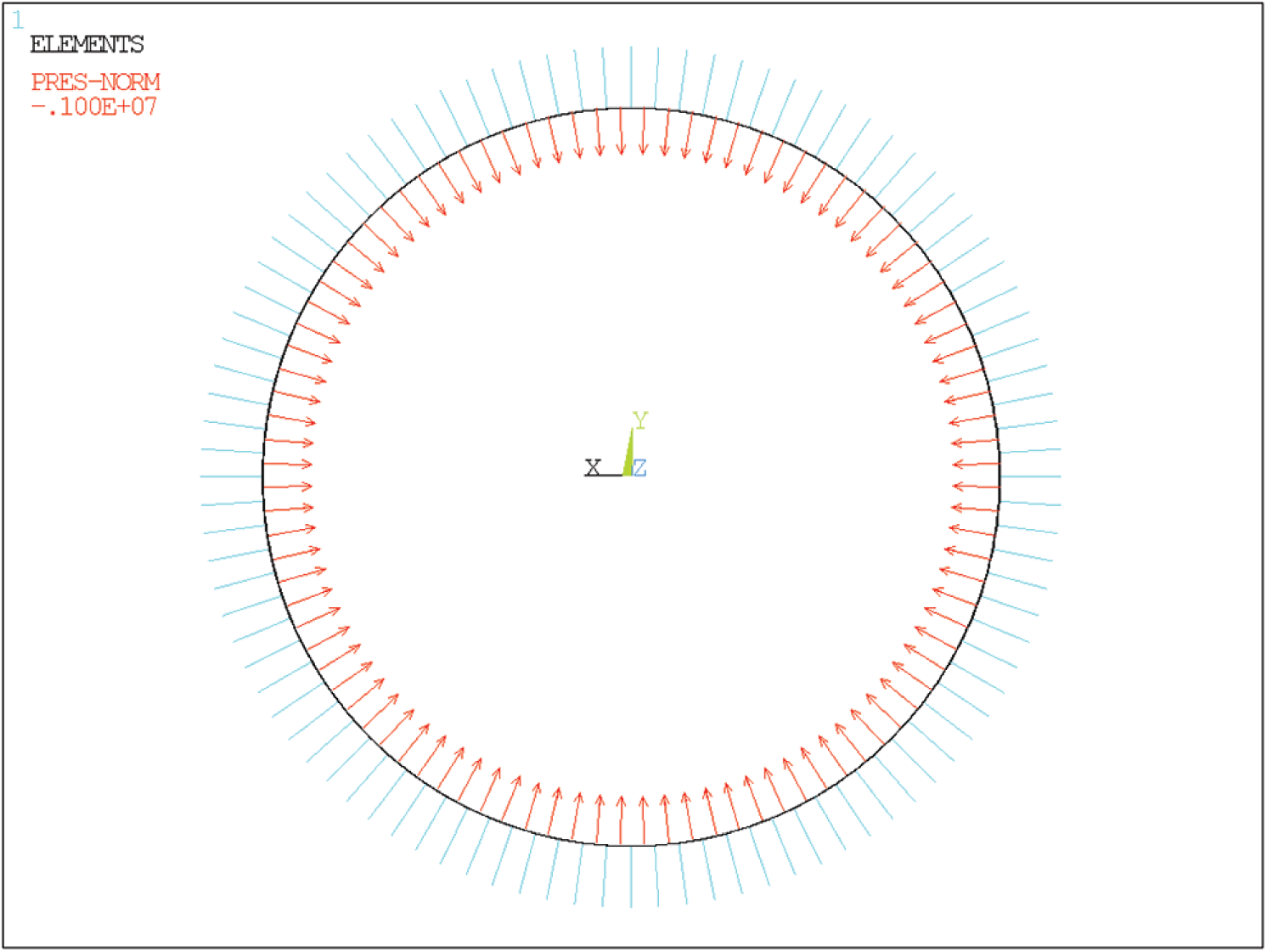
Figure 11: External pressure of the spring element model
The external pressure stability of GFRP pipe under the soil condition of low modulus without gap and high modulus with gap was analyzed respectively. The first-order stability coefficient was extracted to obtain its critical external pressure, as shown in Fig. 12. The calculation results were shown in Tab. 5. Under the soil condition of 5 GPa high modulus with 0.2 mm gap, the stability coefficient of the GFRP pipe was 2.66 and the allowable buckling pressure was 2.66 MPa.
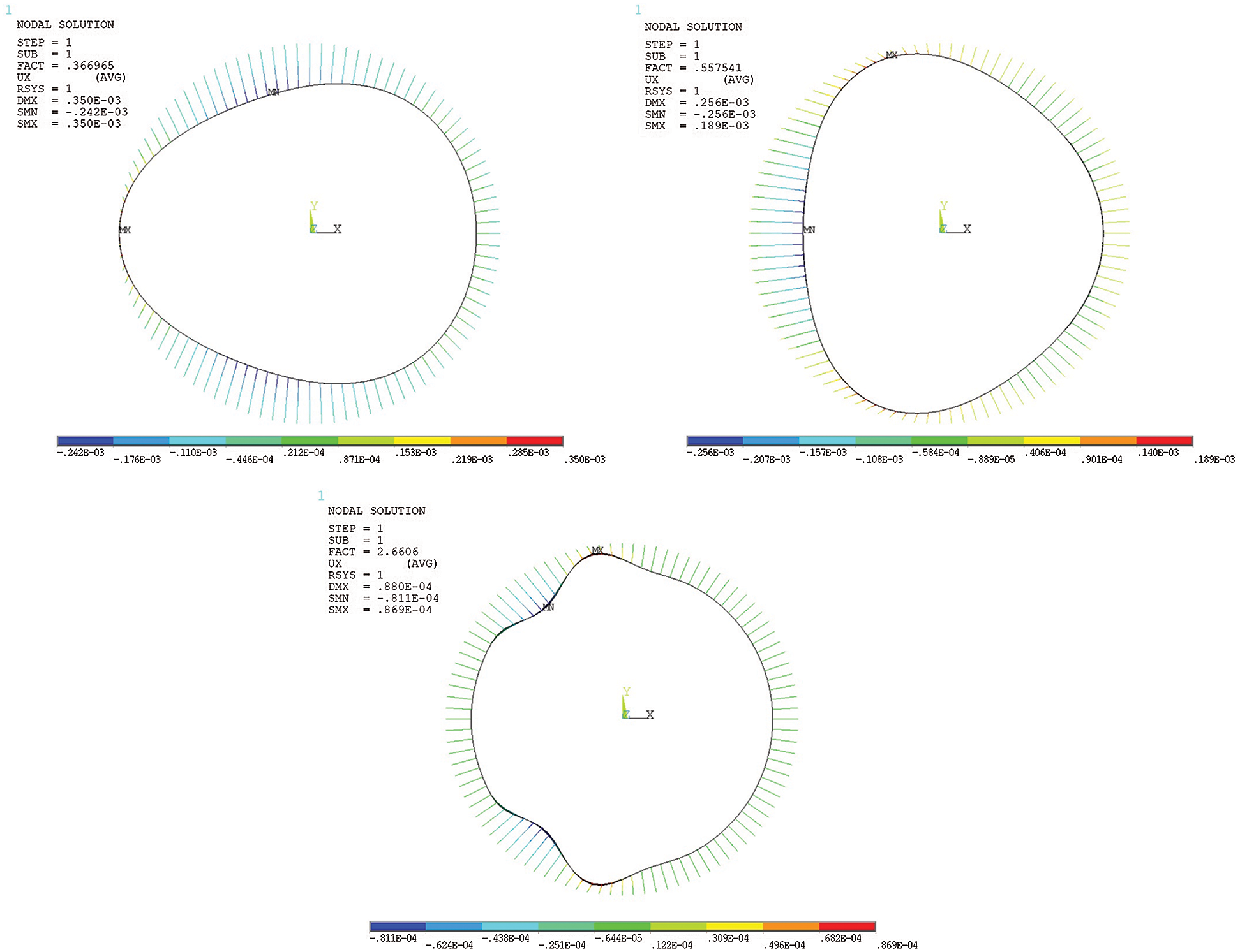
Figure 12: Diagram of stability analysis results
Table 5: Calculation results of the spring element model
4.2 Theoretical Analysis Based on M45 Specification
The American Water Works Association (AWWA) Manual M45, Fiberglass Pipe Design, contains detailed information on the design, specification, procurement and installation of fiberglass pipe and fittings. The M45 manual is usually used for reference and planning of new fiberglass piping design projects. For buckling analysis of buried pipes, the appropriate external load should be equal to or less than the allowable buckling pressure. Due to the restraining effect of soil around the pipe, the external radial pressure that causes the buckling of buried pipe will increase a lot. The allowable buckling pressure in the M45 manual is determined by the following formula [19]:
where, qa is allowable buckling pressure (kPa), FS is design factors, r is average radius of pipe (mm), Cn is scalar calibration factor (0.55), EI is stiffness factor per unit length of pipe wall (N m2/m), and
The M45 buckling formula does not consider the gap between pipe and soil, and is often used to calculate the allowable buckling pressure of buried pipe under low soil modulus, such as 3 and 5 MPa. In this paper, the allowable buckling pressure of GFRP pipe under low soil modulus was calculated by the M45 buckling formula in order to verify the reliability of the pipe-soil spring element model. Due to the effect of the concrete segment and cement paste, the influence of in-situ soil and filling depth need not be considered, FS, kv and Rh were set as 1, 0.74 and 1 respectively. Combined with the material parameters in Tab. 1, allowable buckling pressures of GFRP pipe were 0.376 and 0.529 MPa respectively under the coverage of low modulus’ soil with 3 and 5 MPa. Allowable buckling pressures obtained from pipe-soil model and M45 formula were shown in Tab. 6.
Table 6: Comparison of calculation results

Based on the numerical analysis of finite element and the verification of theoretical formulas, the following research conclusions were obtained in this paper.
A new deep tunnel composite structure lined with GFRP pipe was presented. Based on solid element model, pipe-soil spring element model and theoretical formulas, a set of numerical analysis methods for evaluating the safety and reliability of the structure and guiding its structural design and optimization were proposed.
In internal pressure analysis, the internal pressure was mainly borne by the innermost GFRP pipe. The errors for the external hoop strains of the concrete segments and the GFRP pipe were respectively 3.01% and 5.13%. The stress–strain of each layer obtained by finite element analysis and theoretical calculation was basically consistent, which confirmed the reliability of the C3D8R solid element model in this paper.
A pipe-soil spring element model was proposed to analyze the external pressure stability of GFRP pipe under the soil condition of 5 GPa high modulus with 0.2 mm gap, and allowable buckling pressure of GFRP pipe was 2.66 MPa, which met the external pressure requirement of deep tunnel.
Under the soil condition of 3 and 5 MPa low modulus, the allowable buckling pressures obtained by the M45 were 0.376 and 0.529 MPa, the allowable buckling pressures obtained from the pipe-soil spring element model were 0.367 and 0.558 MPa, with errors of 2.39% and 5.48%, respectively, which confirmed the reliability of the pipe-soil spring element model.
The outer lining of the three-layer structure was concrete segments with high resistance to external pressure, and the inner lining was GFRP pipe with high resistance to internal pressure. The three-layer structure gave full play to the characteristics of the material. The application of GFRP improved the overall performance of tunnel structure. Compared with the traditional cast-in-place prestressed reinforced concrete, it simplified the construction process and greatly improved the quality and safety of construction, which was a safe and economical structure.
Funding Statement: This project was supported by the Fundamental Research Funds for the Central Universities (WUT: 2018IB001) and the Fundamental Research Funds for the Central Universities (WUT: 2019III130CG).
Conflicts of Interest: We declare that we do not have any commercial or associative interest that represents a conflict of interest in connection with the work submitted.
1. Stride, P. (2016). Super sewer: An introduction to the Thames Tideway tunnel project in London. Civil Engineering, 169(CE2), 51. DOI 10.1680/jcien.2016.169.2.51. [Google Scholar] [CrossRef]
2. Edvardsen, C., Solgaard, A., Jackson, P. (2019). Durability design for large sewer and drainage tunnels. In: Tunnels and underground cities: Engineering and innovation meet archaeology, architecture and art, pp. 2061–2070. London: Taylor & Francis Group. DOI 10.1201/9780429424441-218. [Google Scholar] [CrossRef]
3. Wang, G., Zhou, Z. Y. (2016). Application and key technology overview of the city deep tunnel for drainage and water storage. Special Structures, 33, 74–79. DOI CNKI:SUN:TZJG.0.2016-02-016. [Google Scholar]
4. Varadharajan, R. B., Bailey, C. J. (2013). Performance analysis of the storm water management and road tunnel-SMART in Kuala Lumpur. International Journal of Water Resources and Environmental Engineering, 5(7), 410–417. DOI 10.5897/IJWREE2013.0390. [Google Scholar] [CrossRef]
5. Yang, F., Cao, S., Qin, G. (2018). Performance of the prestressed composite lining of a tunnel: Case study of the Yellow river crossing tunnel. International Journal of Civil Engineering, 16(2), 229–241. DOI 10.1007/s40999-016-0124-0. [Google Scholar] [CrossRef]
6. Liang, N., Zhu, S. R., Chen, J. Z., Fang, X. (2015). Long-term behavior of GFRP pipes: Optimizing the distribution of failure points during testing. Polymer Testing, 48(12), 7–11. DOI 10.1016/j.polymertesting.2015.09.015. [Google Scholar] [CrossRef]
7. Ancas, A. D., Profire, M., Cirstolovean, I. L., Hornet, M., Cojocaru, G. (2018). Lifetime glass reinforced plastic pipes by measuring the stiffness. Journal of Applied Engineering Sciences, 8(1), 7–12. DOI 10.2478/jaes-2018-0001. [Google Scholar] [CrossRef]
8. Lee, Y. G., Kim, S. H., Park, J. S., Kang, J. W., Yoon, S. J. (2015). Full-scale field test for buried glass-fiber reinforced plastic pipe with large diameter. Composite Structures, 120, 167–173. DOI 10.1016/j.compstruct.2014.10.002. [Google Scholar] [CrossRef]
9. Goff, S., Trim, M., Grattidge, J., Ager, M., Clarke, B. et al. (2011). The use of glass-fibre reinforced plastic on the Northern Sewerage Project stage 1-design and construction considerations. 14th Australasian Tunnelling Conference: Development of Underground Space, pp. 481–496. Engineers Australia and Australasian Institute of Mining and Metallurgy, New Zealand. [Google Scholar]
10. Griffin, J. (2016). Lengthy microtunnel project beats schedule by 8 months. Underground Construction, 71(9), 30–32. [Google Scholar]
11. Reissner, E., Stavsky, Y. (1961). Bending and stretching of certain types of heterogeneous aeolotropic elastic plates. Journal of Applied Mechanics, 28(3), 402–408. DOI 10.1115/1.3641719. [Google Scholar] [CrossRef]
12. Ansari, R., Gholami, R. (2017). Size-dependent buckling and postbuckling analyses of first-order shear deformable magneto-electro-thermo elastic nanoplates based on the nonlocal elasticity theory. International Journal of Structural Stability and Dynamics, 17(1), 244–246. DOI 10.1142/S0219455417500146. [Google Scholar] [CrossRef]
13. Kulkarni, S. A., Bajoria, K. M. (2003). Finite element modeling of smart plates/shells using higher order shear deformation theory. Composite Structures, 62(1), 41–50. DOI 10.1016/S0263-8223(03)00082-5. [Google Scholar] [CrossRef]
14. Reddy, J. N. (1993). An evaluation of equivalent-single-layer and layerwise theories of composite laminates. Composite Structures, 25(1–4), 21–35. DOI 10.1016/0263-8223(93)90147-I. [Google Scholar] [CrossRef]
15. Chen, J. Z., Lou, Y. S., Lv, Y., Zhang, X. Y. (2018). Analysis on the stability of vertical buried glass fiber reinforced plastic cylindrical shell. Fiber Reinforced Plastics/Composites, 4(1), 23–28. DOI CNKI:SUN:BLGF.0.2018-01-004. [Google Scholar]
16. Kim, S. H., Yoon, S. J., Choi, W. (2019). Experimental study on long-term ring deflection of glass fiber-reinforced polymer mortar pipe. Advances in Materials Science and Engineering, 2019, 1–10. DOI 10.1155/2019/6937540. [Google Scholar] [CrossRef]
17. Rafiee, R., Ghorbanhosseini, A. (2020). Developing a micro-macromechanical approach for evaluating long-term creep in composite cylinders. Thin-Walled Structures, 151, 106714. DOI 10.1016/j.tws.2020.106714. [Google Scholar] [CrossRef]
18. Gherlone, M. (2019). Tria and quad plate finite elements based on RZT(m) for the analysis of multilayered sandwich structures. Composite Structures, 220, 510–520. DOI 10.1016/j.compstruct.2019.04.032. [Google Scholar] [CrossRef]
19. Association, A. W. W. AWWA manual M45-Fiberglass pipe design. Manual of water supply practices. Denver: American Water Works Association. [Google Scholar]
 | This work is licensed under a Creative Commons Attribution 4.0 International License, which permits unrestricted use, distribution, and reproduction in any medium, provided the original work is properly cited. |