Engineering & Sciences
| Computer Modeling in Engineering & Sciences |
DOI: 10.32604/cmes.2021.014947
ARTICLE
Bubble-Enriched Smoothed Finite Element Methods for Nearly-Incompressible Solids
1University Core Research Center for Disaster-Free and Safe Ocean City Construction, Dong-A University, Busan, 49315, Korea
2Department of Mechanical Engineering, Indian Institute of Technology Madras, Chennai, 600036, India
3Faculty of Science, Technology and Communication, University of Luxembourg, Esch-sur-Alzette, L-4364, Luxembourg
4CISTIB-Center for Computational Imaging & Simulation Technologies in Biomedicine, School of Engineering, Leeds, LS2 9JT, UK
*Corresponding Authors: Jurng-Jae Yee. Email: jjyee@dau.ac.kr; Stéphane P. A. Bordas. Email: stephane.bordas@uni.lu
Received: 10 November 2020; Accepted: 04 January 2021
Abstract: This work presents a locking-free smoothed finite element method (S-FEM) for the simulation of soft matter modelled by the equations of quasi-incompressible hyperelasticity. The proposed method overcomes well-known issues of standard finite element methods (FEM) in the incompressible limit: the over-estimation of stiffness and sensitivity to severely distorted meshes. The concepts of cell-based, edge-based and node-based S-FEMs are extended in this paper to three-dimensions. Additionally, a cubic bubble function is utilized to improve accuracy and stability. For the bubble function, an additional displacement degree of freedom is added at the centroid of the element. Several numerical studies are performed demonstrating the stability and validity of the proposed approach. The obtained results are compared with standard FEM and with analytical solutions to show the effectiveness of the method.
Keywords: Strain smoothing; smoothed finite element method; bubble functions; hyperelasticity; mesh distortion
The deformation of soft matter, which can be modelled using the equations of hyperelasticity, is an important problem with applications throughout the physical sciences and engineering. Such soft matter, e.g., rubbers, polymers and human soft tissues, behave in a geometrically and materially non-linear manner characterized by large deformations and nearly incompressible behaviour. It is important to design numerical approaches that provide robust and accurate simulation for scientists and engineers [1]. The first step to numerically solve such problem is to obtain a subdivision of the problem domain as automatically (without user intervention) and rapidly as possible. In the context of finite element methods, this operation is called mesh generation. Meshes consisting of low-order simplex tetrahedral cells (triangulations) are best suited to automatic mesh generation and there exist schemes that allow the generation of millions of tetrahedral elements per second [2]. However, finite elements defined on simplex tetrahedral cells are also notorious for the excessive stiffness and the sensitivity to volumetric locking. Rabczuk et al. [3] discussed a possibility of non-mesh based method to handle incompressibility undergoing large deformations. However, this work focuses on development of an alternative approach which leads to use simplex tetrahedral cells. Therefore, the strain-smoothed approach in the framework of finite element approximation [4–6] (so-called smoothed finite element methods—S-FEM) is an another possible option to address the following issues in the context of simulating soft matter: 1) volumetric locking associated with nearly- and fully-incompressible materials and 2) the difficulty of generating quality subject-specific meshes. The method relies on the smoothed deformation gradient, which therein is assumed homogeneous over smoothing domains.
Various 3D strain smoothing approach variants have been introduced. Firstly, Nguyen-Thoi et al. [7] used the face-based smoothed finite element method (FS-FEM) for linear and geometrically non-linear problems. Viscoelastoplastic problems are successfully addressed by the face-based strain smoothing [8] and 3D extension of node-based smoothed finite element method (NS-FEM) [9], both of which show higher efficiency than FEM and the edge-based smoothing method. Cazes et al. [10] presented 3D-extended edge-based smoothed finite element method (ES-FEM) for solid problems. Not only solid problems but also coupled structural-acoustic problems are tackled by smoothed finite element methods. He et al. [11] used a coupled 3D ES-FEM/FEM formulation, with ES-FEM and FEM applied to structure and fluid parts, respectively, while Li et al. [12] used a coupled ES/FS-FEM approach for solid and fluid. Moreover, to handle heat transfer and thermal mechanical problems, Feng et al. [13] used face-based S-FEM (FS-FEM) and Cui et al. [14] used cell-based S-FEM (CS-FEM). In particular, Cui and colleagues employed cell-based strain smoothing approach with the meshless radial point interpolation method to obtain the radial basis function on smoothing domains. Other hybrids of node- and edge-based smoothed finite element methods with meshless point interpolation methods for heat transfer problems are presented by Wu et al. [15,16]. Natarajan et al. [17] constructed cell-based polyhedral S-FEM with one sub-cell. To stabilize the polyhedral S-FEM, they adapted the stabilizing term of the virtual element method to S-FEM without increasing the number of smoothing domains. Additionally, further applications for linear fracture problems were investigated by 3D ES-FEM by Zeng et al. [18], employing singular 7 node tetrahedral elements for the crack front.
The application of main interest of this work, i.e., soft materials, has been also considered by Jiang et al. [19,20]. They employed the selective 3D-ES/NS-FEM and FS/NS-FEM to solve nearly-incompressible hyperelastic models. To use the selective S-FEM, the strain energy density is split into two parts: the deviatoric and volumetric. Since it is known that ES-FEM is immune to the distorted meshes and NS-FEM can avoid the over-stiffness phenomenon [21], the deviatoric part of the strain energy density is solved by 3D-ES- and FS-FEM while NS-FEM tackles the volumetric part.
Instead, in the present work, we employ a cubic bubble function to enrich S-FEM [22,23]. The study of Ong et al. [23] showed that the inf-sup condition for the bubble-enriched S-FEM was satisfied in small deformation cases and Lee et al. [22] used the concept of the bubble-enhanced S-FEM to analyze large deformation problems in the quasi-incompressible hyperelastic limits. In this paper, the suggested bubble function is integrated into two strain-smoothed approaches, 3D-edge-based and face-based smoothing methods to deal with the distorted meshes in near-incompressibility.
An outline of this paper as follows: in the following section, the basic properties of cell-based, edge-based, face-based and node-based gradient smoothing approaches extended to three-dimension in the framework of finite elasticity are recalled. In the next section the bubble-enhanced smoothed FEM is formulated for the hyperelastic neo-Hookean material. In the penultimate section numerical tests including large deformation and insensitivity to mesh distortion in incompressible models are studied with several cases of soft materials parameters, e.g., polymers and human organs. In the final section, we draw a conclusion to remarks of the proposed methods and give some possible ideas for future work.
2 Review of Gradient-Smoothed Finite Element Approximation
Many existing studies of strain-smoothed finite element approaches describe their basic formulation and properties. We briefly revisit the background of the strain-smoothed method in this section. The basic idea behind S-FEM is to divide the computational domains into sub-domains wherein gradients are smoothed. Gradients are constant over the smoothing domains but are discontinuous across the boundaries of smoothing domains. Sub-domains are usually constructed using the topology provided by the mesh. Depending on this construction, various solution behaviors are observed, offering the use of a spectrum of methods with particular properties [5,24].
The salient abilities of S-FEM are its insensitive to locking and to element distortion [22]. The integration for S-FEM is performed in the global space, hence the Jacobian transformation from the local to global space is obviated. Moreover, since the bandwidth of the stiffness in the smoothed-strain method is wider than in the existing FEM, there is a potential to design methods without over-estimated stiffness.
Four different types of S-FEM have been introduced, depending on how the smoothing domains are built [21]: cell-based (CS-FEM), edge-based (ES-FEM), node-based (NS-FEM) and face-based (FS-FEM). In this section, we extend the idea of two-dimensional cell-based, edge-based and node-based smoothing to three-dimension and Figs. 1–4 illustrate how to construct the smoothing domains for each strain-smoothed technique.
2.1 Cell-Based Smoothing Domain
In the cell-based S-FEM four sub-cells are constructed by splitting the tetrahedron about its centroidal point. Fig. 1 shows sub-cells and smoothing domains for CS-FEM. In Fig. 1a, it is shown that how a tetrahedral cell with vertices labelled 1234 can be divided into four tetrahedral sub-cells by point 5, the centroid of tetrahedron. These sub-cells are new domains where the so-called smoothed strain can be constructed. Fig. 1b shows an example of the selection of the cell-based smoothing domain when two cells, tetrahedron 1234 and tetrahedron 2345, are neighbored. The cells 1234 and 2345 share a triangular face 234, and points 6 and 7 are the centroids of the respective tetrahedra. When the target cell 2357 is chosen, its smoothing domain is constructed as itself, a sub-cell 2357. The concept of the construction of the cell-based smoothing domain has strong similarities with the standard finite element method.
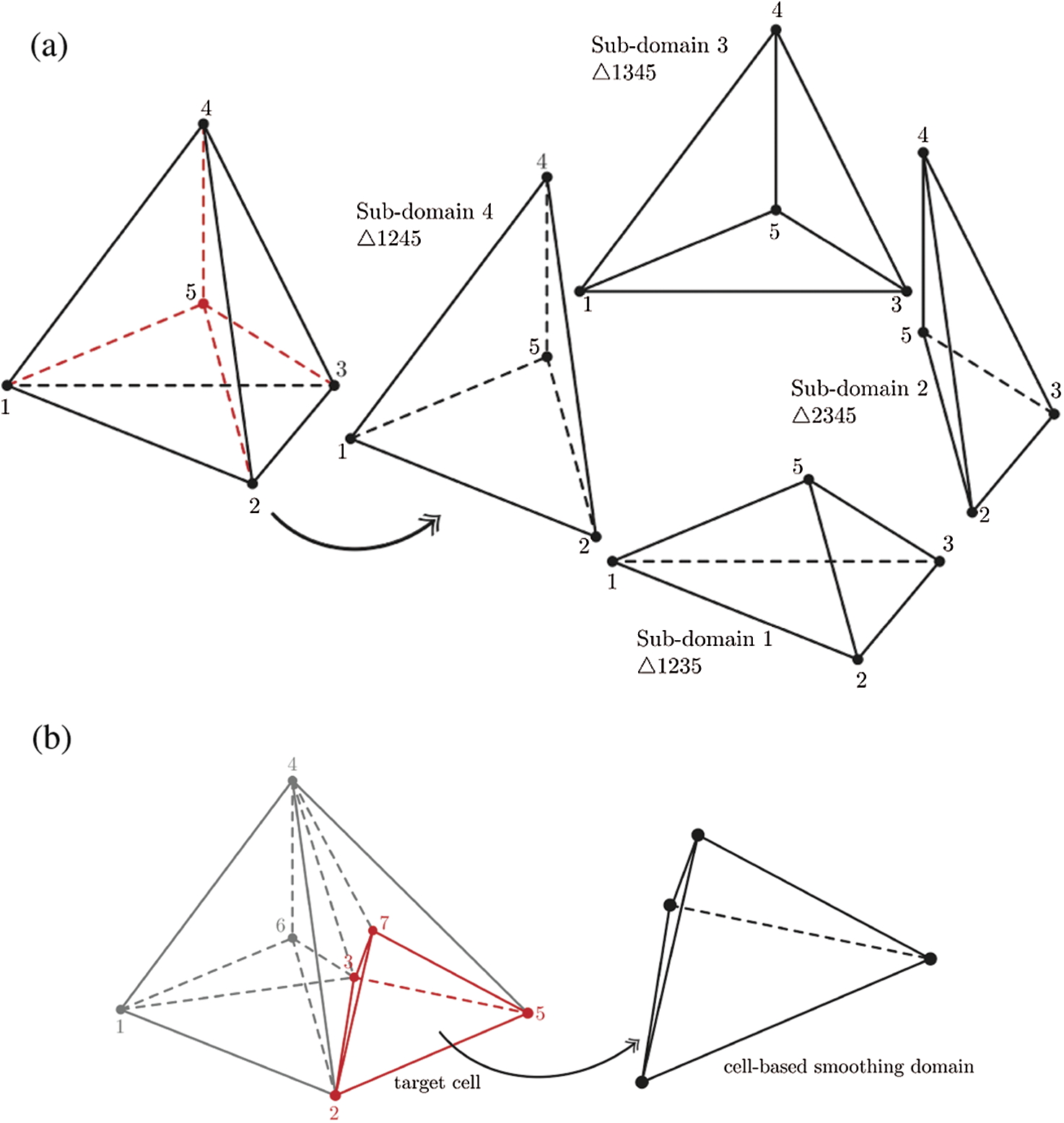
Figure 1: 3D-extended-cell-based smoothing approach. (a) The construction of sub-cells for CS-FEM and (b) target cell and its smoothing domain
2.2 Face-Based Smoothing Domain
The basic idea of FS-FEM is the extension of the 2D edge-based smoothing method to 3D, meaning that the target edge of a triangular cell is transferred to the faces of the tetrahedral cell as shown in Fig. 2.
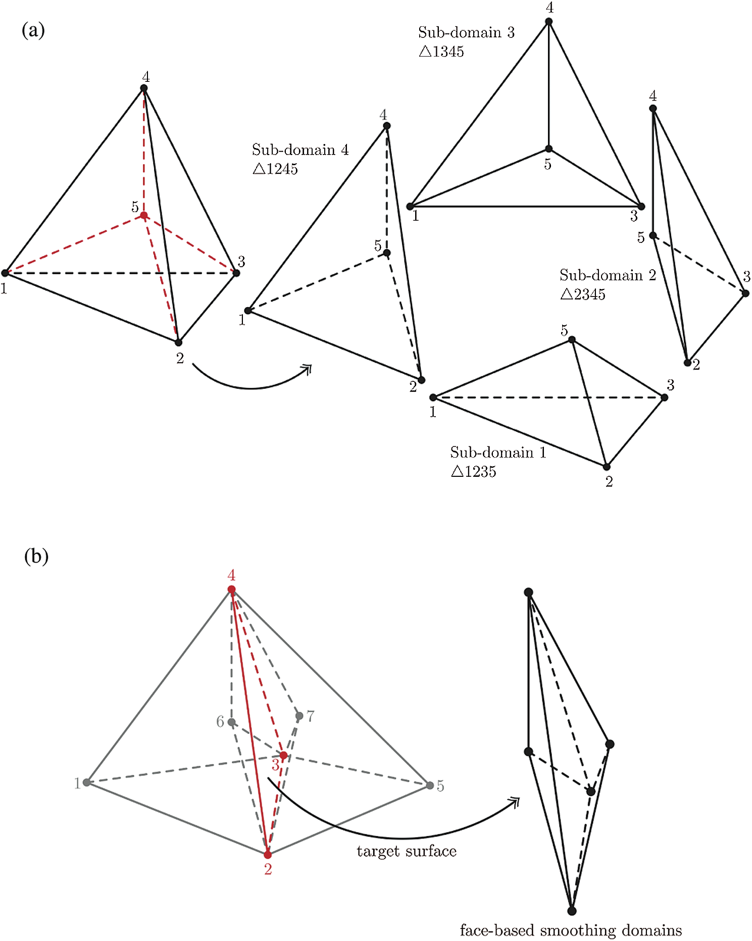
Figure 2: Face-based smoothing approach: (a) The construction of sub-cells for FS-FEM and (b) target face and its smoothing domain
In the same manner to CS-FEM, the tetrahedral cell is split into four tetrahedral sub-domains by the centroidal point of the cell as shown in Fig. 2a. In the case that any of the faces of the tetrahedral cell is located on the boundary of the problem domain, the face-based smoothing domain is only one sub-cell and contains boundary surface. Now let us suppose the target face (
2.3 Edge-Based Smoothing Domain
Assembling the edge-based smoothing domain in three-dimensions is rather more complex than in its two-dimensional counterpart. Fig. 3 illustrates the division of a cell into sub-cells geometrically and assembly of sub-cells to form a smoothing domain around a target edge. Firstly, to create sub-cells for ES-FEM, five new points must be generated at the centroid of the cell and the centroids of the cell’s four faces. Then, as shown in Fig. 3a, sub-cells associated with each edge are created from the nodes of those edges, the cell centroid, and the centroids of the two respective adjoining faces. The number of sub-cells for ES-FEM is six since each tetrahedral cell has six edges. Fig. 3b depicts the construction of the smoothing domain associated with the target edge.
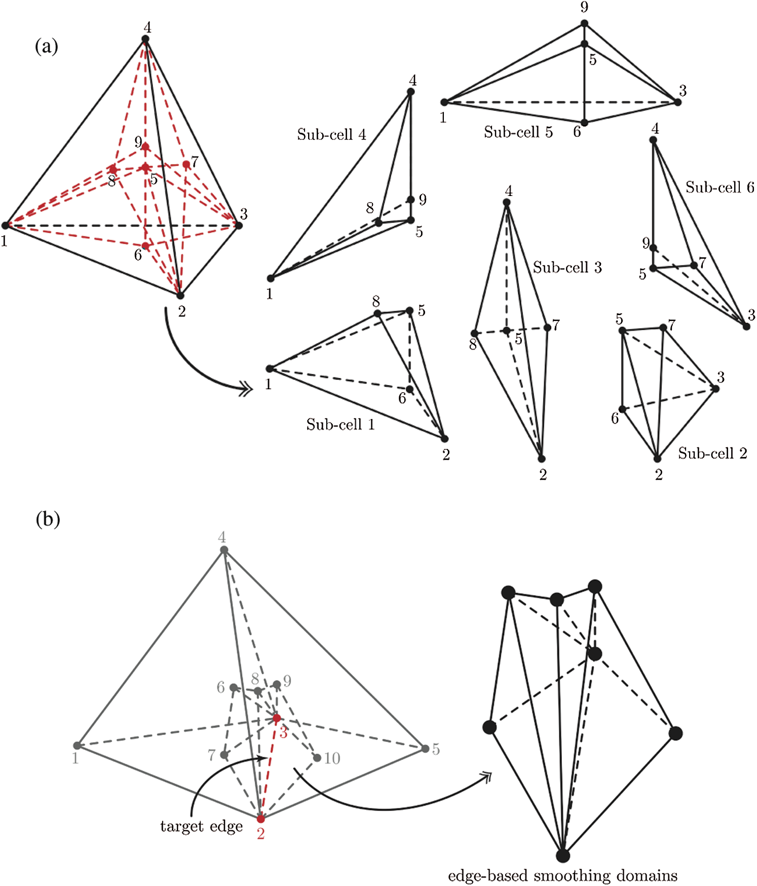
Figure 3: 3D-extended-edge-based smoothing approach: (a) The construction of sub-cells for ES-FEM and (b) target edge and its smoothing domain
2.4 Node-Based Smoothing Domain
For NS-FEM, the tetrahedral cell is divided into four hexahedral sub-domains based around the four nodes. To create the hexahedral sub-domains, we construct 11 additional points: the centroid of the cell (1), the centroid of each face (4), and centroid of each edge (6). Then the sub-cells are constructed from the four original vertices and 11 additional points as shown in Fig. 4a. Assembly of sub-cells from adjoining elements to form the smoothing domain around a target node is illustrated (for the case of node 2) in Fig. 4b.
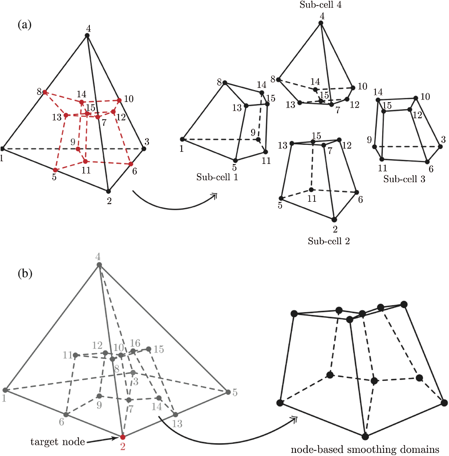
Figure 4: 3D-extended-node-based smoothing approach: (a) The construction of sub-cells for NS-FEM and (b) target node and its smoothing domain
Integrals are evaluated over smoothing domains using a Gauss integration scheme. Sample points, at which shape functions and outward normals are computed, are located in the middle of each face of the smoothing domain [25]. Fig. 5 depicts the positions of Gauss points for the face-based smoothing.
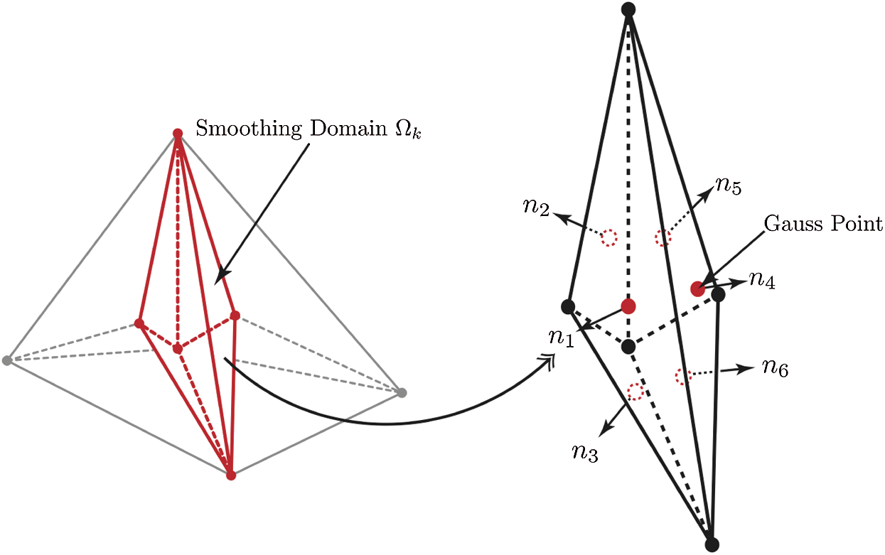
Figure 5: Gauss integration scheme: The smoothing domain associated with the target face with Gauss points and outward normals on each surface for FS-FEM
Note that red circles are Gauss points located at the centroid of each surface of the element and
3 Strain Smoothing Approximation
To formulate the non-linear strain smoothing approximation in the following section, we recall the fundamentals of smoothed finite element approximation. The infinitesimal strain tensor
where
where a point
The smoothed strain can be obtained as follows, applying the divergence theorem:
where Vk is the volume of smoothing domain
The discrete trial and test functions are expanded in terms of linear Lagrange shape function
When the strain in each sub-domain is constant, the smoothed strain can be written as:
where
4 Smoothed Finite Element Approximation in Finite Elasticity, Enhanced by the Bubble Function
To solve the non-linear equilibrium equations, we adopt the Newton–Raphson iterative method. The detailed information could be found in [22,26], but we herein briefly explain the smoothed Galerkin weak form and its linearization.
where
where Gk is a set of nodes and
Eq. (9) can be defined to the energy function
and
where
To solve Eq. (9) approximately, the Newton-Raphson method is utilized in this work:
therefore, the energy functional Eq. (11) and its directional derivatives Eq. (12) can be rewritten:
where
Eq. (13) can be assembled into matrix form at every iteration given as:
where the smoothed tangent stiffness matrix
where Nt is the number of target cells, edges, vertices and faces,
The load vector
where
The smoothed global system of equations for Eq. (13) at each iteration can be written as:
thus the displacement
The domain-based selective strain smoothing finite element approximation was suggested due to the fact that the edge-based strain-smoothed method does not fully overcome locking [11]. Recent study of the domain-based S-FEM showed that the selective S-FEM can alleviated locking [19,20]; however, an additional treatment is required the discretized equations for the each strain smoothing approach.
For this reason, Nguyen-Xuan et al. [27] proposed the mixed displacement-pressure formulation in the framework of the edge-based smoothing method using the cubic bubble function and its mathematical properties about the stability of the inf-sup condition were provided by Ong et al. [23]. The bubble function requires the supplement of an additional degree of freedom for the displacement field approximation at the centroid of the element. At the centroid of the element, only the linear displacement field exists as the unknown field in the bubble-enriched gradient smoothing because the strain smoothing approach is based on displacement-based formulation. The bubble function is given with four linear basis functions and the cubic bubble function for the tetrahedral element as follows:
Since Eq. (21) does not satisfy the partition of unity, the basis function necessarily requires the transformed form can be obtained as:
Hence the transformed bubble basis function can be expressed as:
where the properties of the bubble is given as:
meaning that the bubble function has a value one at the center of the element and the value is zero on the boundaries of the element.
A series of test problems is used to assess the effectiveness of the proposed method in dealing with the shortcoming explained in the previous section: simple torsion of a rectangular block, Cook’s membrane, a hollow cylinder and a cube.
To test near-incompressibility we use the following soft materials: polymers, e.g., polyurethane, and human tissues. Both soft media exhibit the nonlinear strain-stress behaviour commonly associated with highly deformable materials, and their Poisson’s ratios are close to 0.5. Polyurethane is mainly used in energy absorption applications, such as packaging or the cushion of padded chairs [28]. In this work, we model a Polyurethane spring which is currently used in a base isolation device to regulate mass energy from earthquakes using its reversible deformation property. Human soft tissues can sustain large deformations and, due to their high water content, are nearly incompressible. Correspondingly, they are frequently modelled as hyperelastic materials. In our test case, we employ the quasi-incompressible neo-Hookean model used by Taylor et al. [29] to model brain material.
Another aspect that we consider is the mesh distortion sensitivity. To study the influence of the mesh distortion, finite element meshes are artificially distorted, changing the position of a vertex randomly in each direction.
For all numerical examples the following parameters for the Newton iteration method are used: tolerance 10−9,
In this section we investigate the performance of the proposed method for quasi-incompressibility, with Poisson’s ratio
5.1.1 Simple Torsion of a Rectangular Block
Firslty, the non-homogeneous Dirichlet boundary conditions (BCs) problem in quasi-incompressible limit is considered. Simple torsion of a rectangular block is used with human brain-like material [29]: the shear modulus
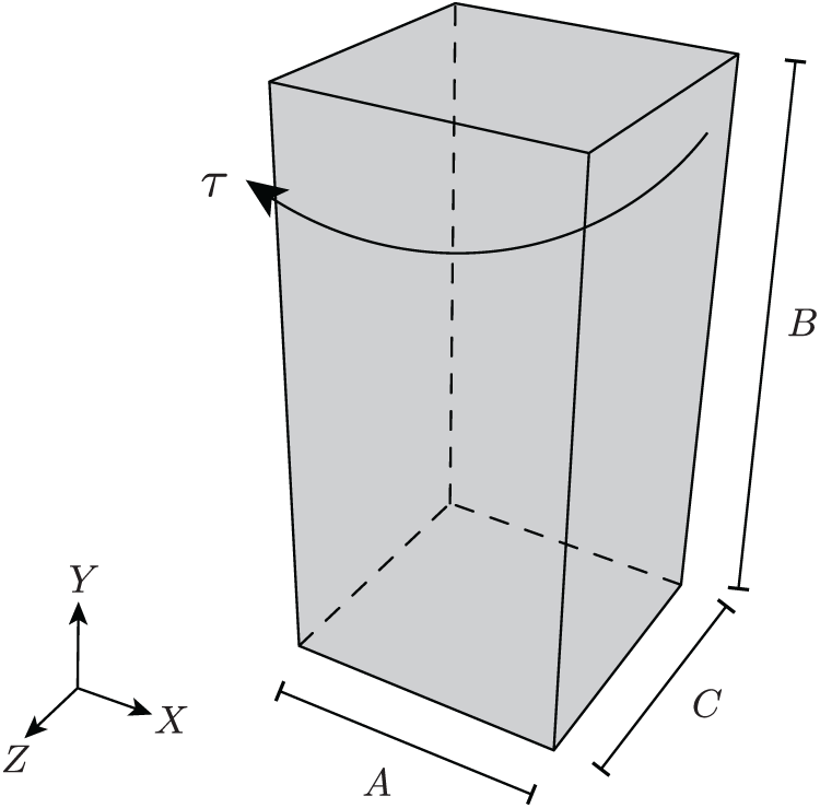
Figure 6: The geometry of the rectangular block
For this test, cylindrical coordinates and Dirichlet BCs based on a solid cylinder are needed; however cylindrical coordinates and Dirichlet BCs are transformed to Cartesian coordinates and imposed to a rectangular solid (further details can be found in [26]). The deformation in cylindrical polar coordinates are given as:
where the torsion per unit length
Then, cylindrical coordinates are formulated to the following Cartesian coordinates:
where
Fig. 7 shows deformed configurations of the rectangular blocks obtained by each method and Fig. 8 illustrates the convergence of strain energy errors for the block, respectively.
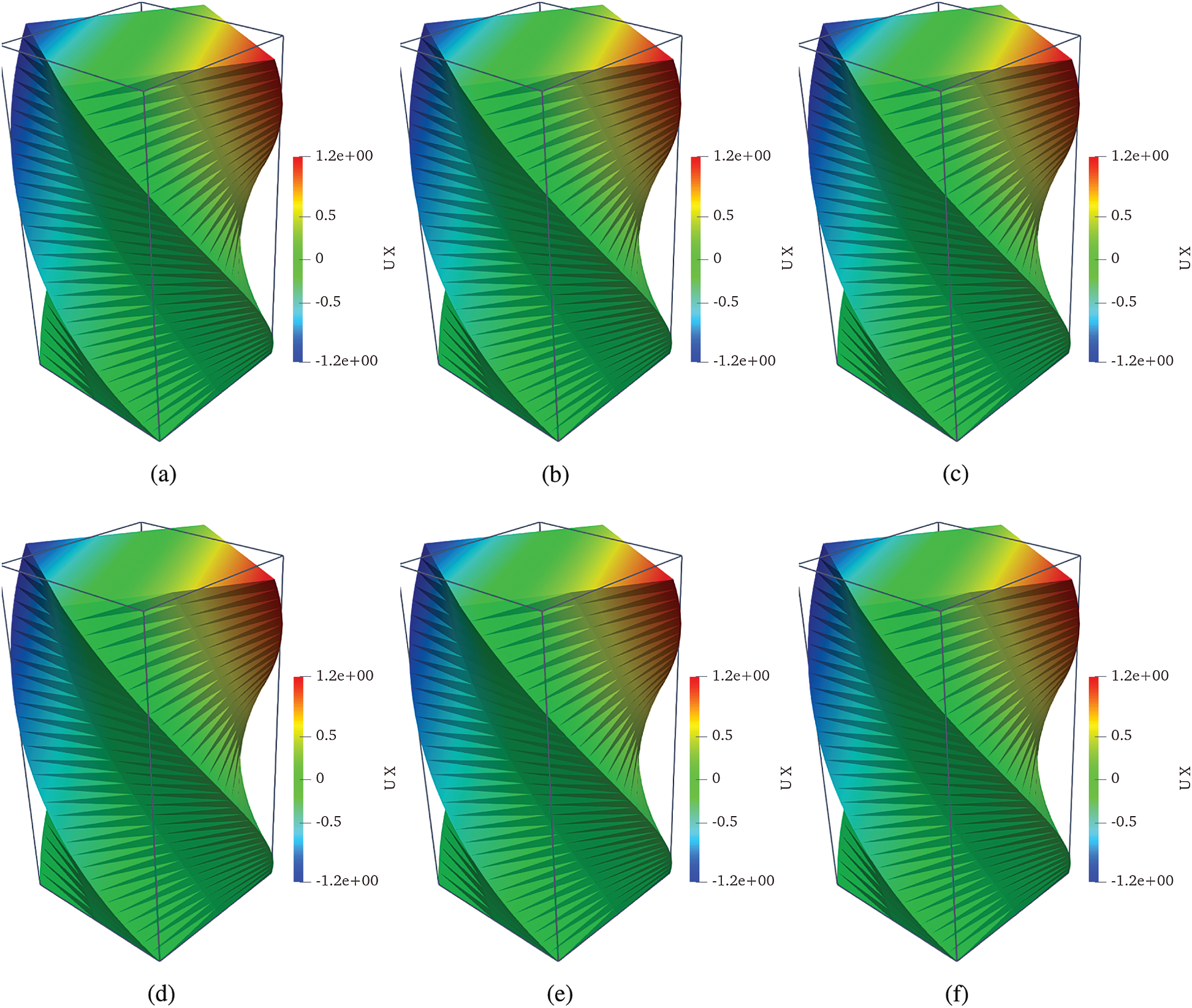
Figure 7: Deformed shapes of the rectangular block. (a) FEM T4, (b) cell-based S-FEM T4, (c) face-based S-FEM T4, (d) edge-based S-FEM T4, (e) node-based S-FEM T4 and (f) face-based S-FEM with bubble enrichment
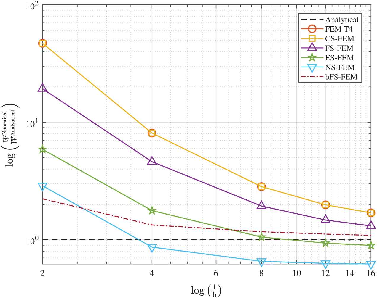
Figure 8: The convergence of the relative errors in strain energy for simple torsion of the rectangular block
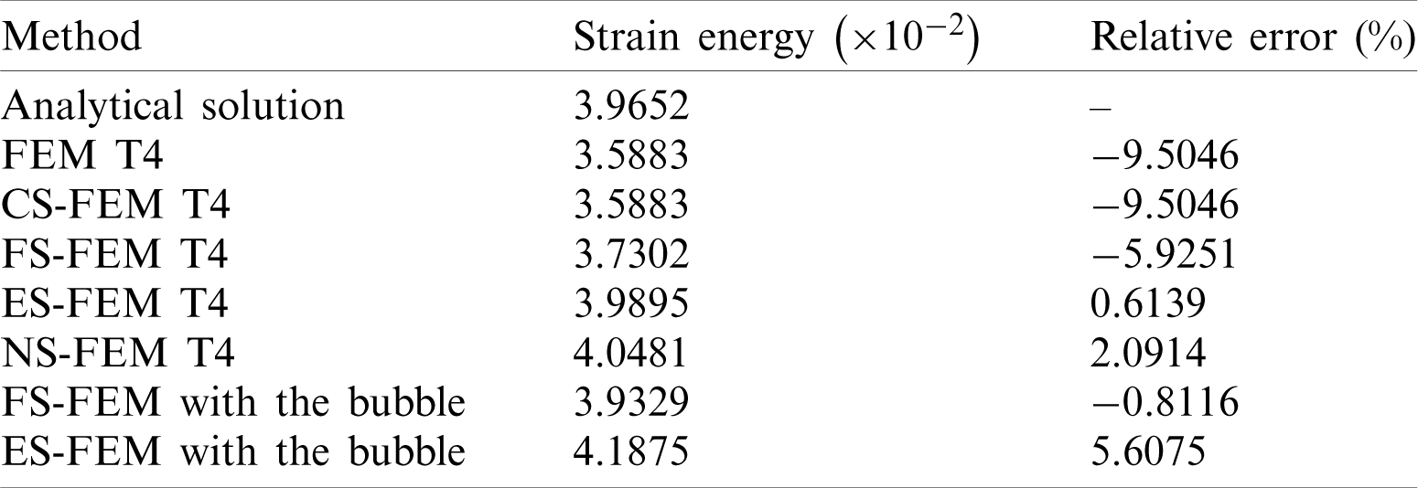
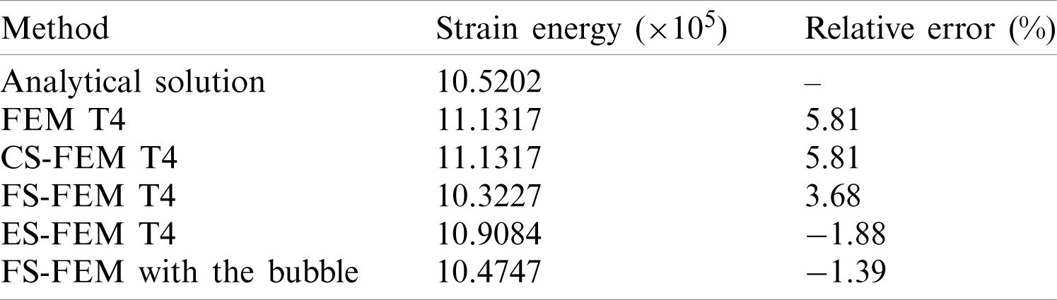
The number of elements along to x- and z-axes is 2 and the numbers of elements in y-axis are 4, 8, 16, 24 and 32. As shown in Fig. 7 and Tab. 1, the bubble-enhancement leads to improve the accuracy,, FEM and CS-FEM provide identical results. 3D edge-based and node-based smoothing strain methods show the minus values of the relative error in strain energy, meaning their strain energies are smaller than the analytical solution. FS-FEM shows around 31% of the relative error, while its bubble-enhanced approach gives only about 9% of the error. It is clearly shown that the bubble-enhancement is able to reduce almost 71% of the error and it helps to increase.
Table 1: Strain energy relative error for simple torsion of the rectangular block
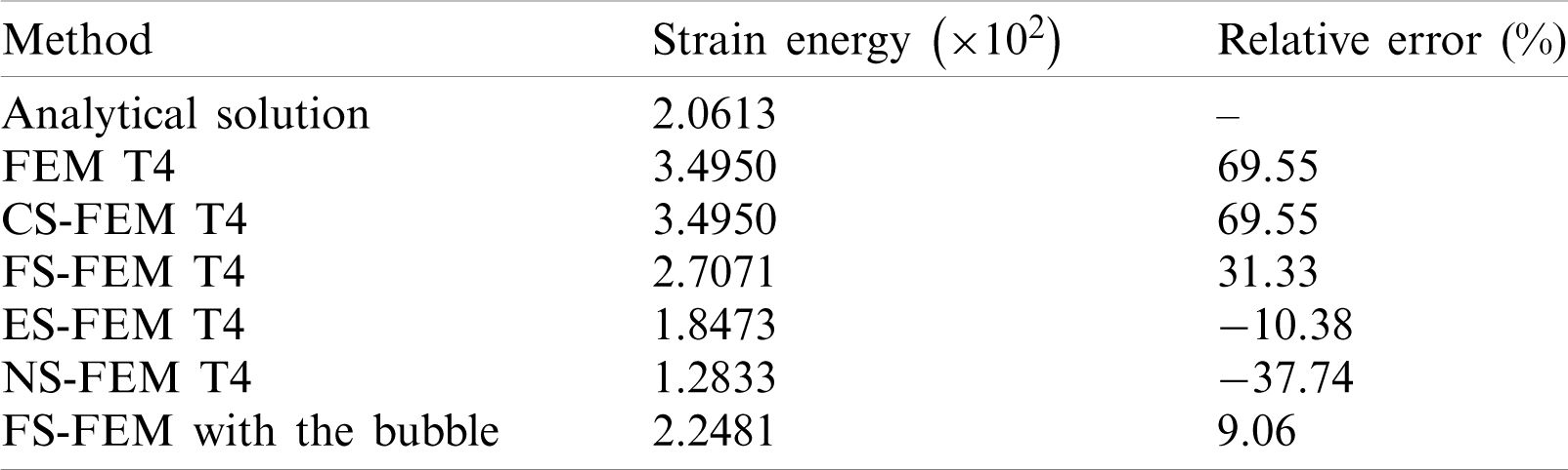
where strain energy relative error is obtained as follows:
Tab. 2 provides the computational time for the standard FEM, the standard S-FEM and the proposed enriched S-FEM. To obtain the computational time, the following computer system is used: Matlab R2019b running on Windows 10 with
Table 2: Computational time of the polyurethane spring for FEM and each S-FEM
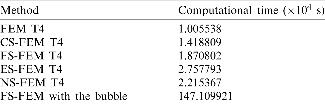
It is known that the bandwidth of the stiffness matrix for S-FEM is larger than the standard FEM; therefore, in general, S-FEM needs more computational time than the standard FEM. As given in Tab. 2, FS-FEM and 3D-NS-FEM are around two times slower than the standard FEM and 3D-ES-FEM needs almost three times more computational effort to converge the problem. On the other hand, the computational cost of the bubble-enriched FS-FEM is the most expensive among the present approaches. However, as shown in Fig. 8 and Tab. 1, the bubble-enhancement leads to improve the quality of result meaning that with coarser meshes the bubble-enriched S-FEM provides the relatively accurate results.
In this section, the well-known Cook’s membrane is investigated. The geometry is shown in Fig. 9 with
The structure is a cantilever, therefore fixed boundary conditions are implemented as:
• Left surface
and a bending force (
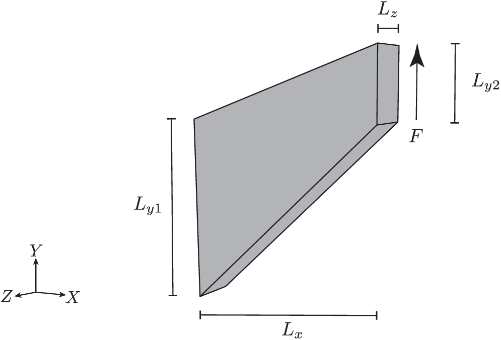
Figure 9: The geometry of the Cook’s membrane
The deformed configurations of Cook’s membrane obtained by reference solution (MINI element) and the proposed strain smoothing approaches are shown in Fig. 10. Fig. 11 illustrates the convergence rate of the relative error in strain energy of Cook’s membrane and the detailed values are provided in Tab. 3. As shown in Fig. 11 and Tab. 3, FEM and CS-FEM show identical results and this phenomenon is also shown in the aforementioned non-homogeneous Dirichlet BCs problem. The most accurate result is obtained by ES-FEM with about 0.6% of error and the bubble-enhanced FS-FEM provides around 0.81% of error in strain energy. As shown in Tab. 3, the bubble-enhanced FS-FEM gives relatively accurate results among others, while FS-FEM shows almost 6% of error. It is clearly seen that the bubble-enhancement leads to an increase in the accuracy of results by about 86% compared to the standard FS-FEM. The notable result obtained in the present test is the bubble-ES-FEM which produces a worse result that is around eight times higher error than ES-FEM and as well as NS-FEM shows three times higher error.
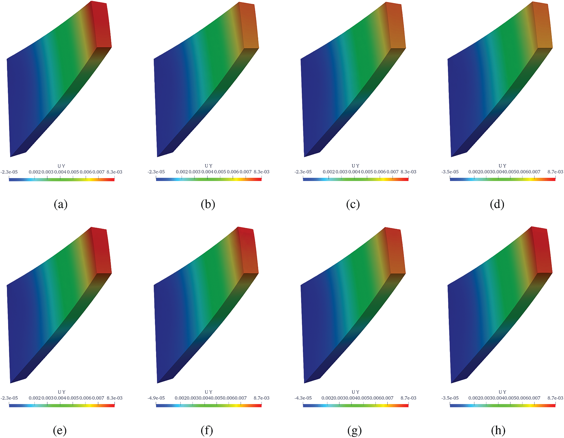
Figure 10: Deformed shapes of Cook’s membrane. (a) Reference (MINI element), (b) FEM T4, (c) cell-based S-FEM T4, (d) face-based S-FEM T4, (e) edge-based S-FEM T4, (f) node-based S-FEm T4, (g) face-based S-FEM with bubble enrichment and (h) edge-based S-FEM with bubble enrichment
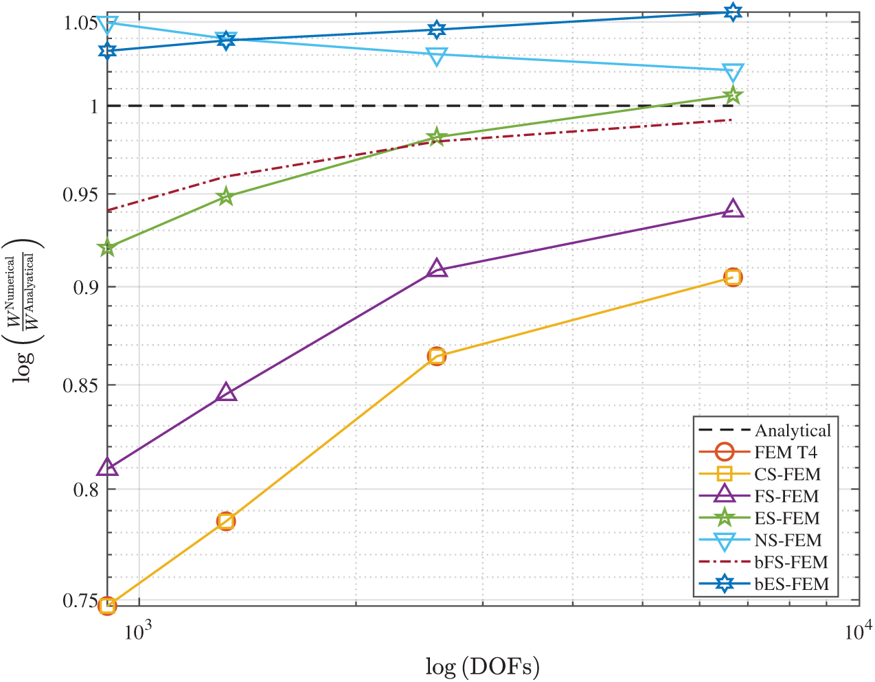
Figure 11: The convergence of the strain energy for the Cook’s membrane. Note that FEM T4 and CS-FEM lines are overlapped since their results are identical
Table 3: Cook’s membrane: Relative error in the strain energy for different approaches
5.1.3 Pressure of a Hollow Cylinder
In this section, Polyurethane MER (Mass Energy Regulator) spring used for the seismic base isolation unit (EQS, Eradi Quake System), developed by ESCO RTS2. The basic idea of the EQS unit is that the seismic force can be absorbed by the disk bearing and the horizontal force is dissipated by the MER spring.
The details of the device are given in Fig. 12a: 1. Guide box, 2. PTFE (Polytetrafluoroethylen), 3. MER spring, 4. Polyurethane disk, and 5. Shear Pin. Fig. 12b shows the assembled device as used in the experiments.
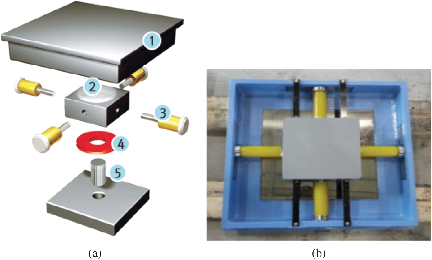
Figure 12: Details of EQS device and MER spring. (a) Exploded view of EQS seismic base isolator and (b) the assumed device as used
To model polymer polyurethane material, neo-Hookean hyperelastic limit is again used. Shear and bulk moduli are
• Bottom surface
• Top surface
Considering the instability of NS-FEM and bES-FEM observed in the previous section, only CS-FEM, ES-FEM, FS-FEM and the bubble-FS-FEM are examined in this section. Fig. 13 illustrates deformed configurations of the polyurethane spring for respective S-FEM approaches and for the MINI element obtained by DOLFIN software.
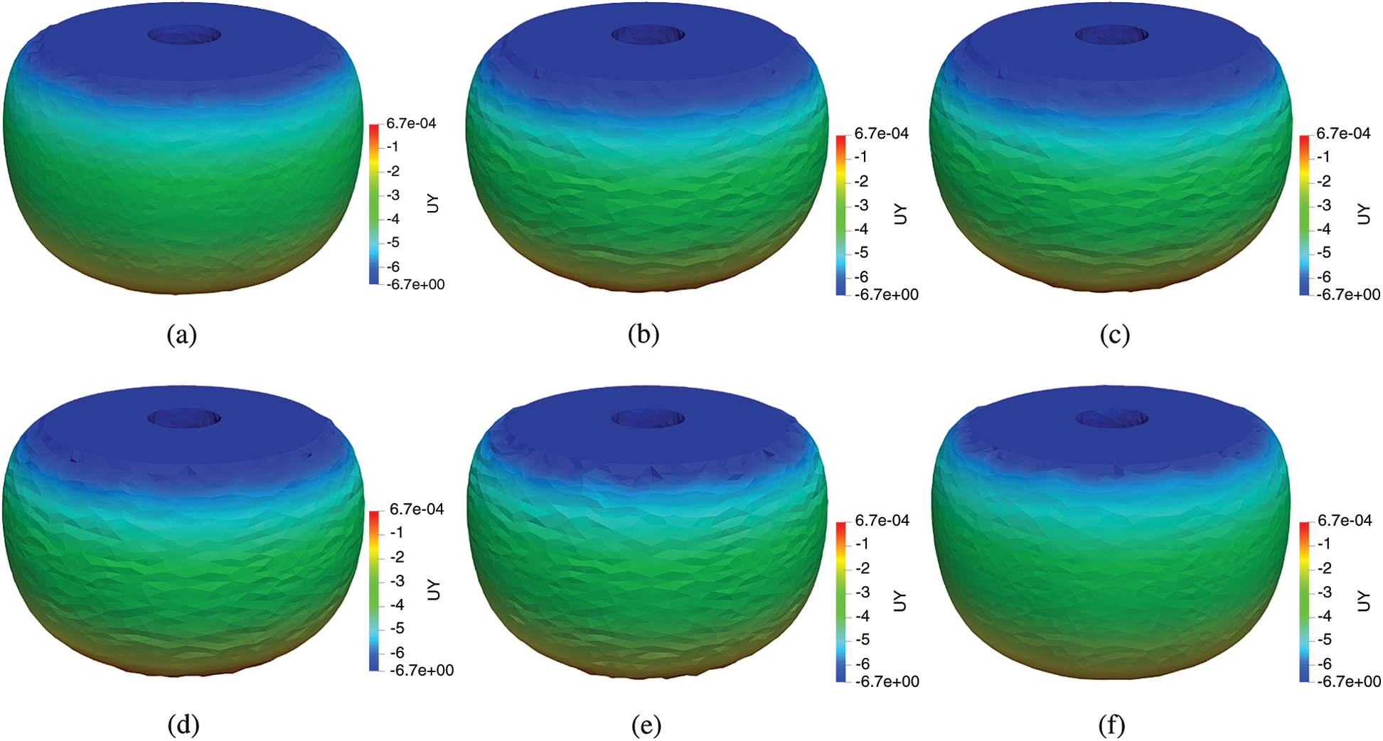
Figure 13: Deformed shapes of the polyurethane spring. (a) MINI element, (b) FEM T4, (c) cell-based S-FEM T4, (d) face-based S-FEM T4, (e) edge-based S-FEM T4 and (f) face-based S-FEM with bubble enrichment
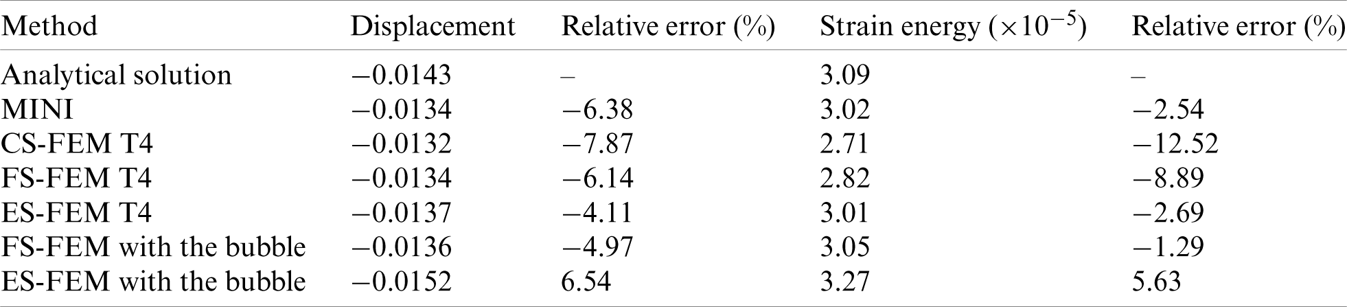
The deformation predicted by bFS-FEM is similar to that of the reference solution, while other methods produced somewhat different patterns. Distinct improvements in the strain energy results were also observed, as shown in Tab. 4. CS-FEM and FEM, again, produce the same results, and cannot avoid locking in quasi-incompressibility. The edge-based smoothing is more accurate than the face-based smoothing; however, the bubble-enrichment notably increases the accuracy retaining the stability. The bubble-face-based smoothed finite element method is able to improve the accuracy about three times and it also shows around 26% less error in strain energy compared to ES-FEM.
Table 4: Strain energy relative error for the polyurethane spring
5.2 Mesh Distortion Sensitivity
Lastly, in this section, the mesh distortion sensitivity for the proposed approach for quasi-incompressible problem is investigated. For this test, regularly distributed finite element cell meshes are artificially distorted by the following terms [24]:
where
A cube model under compression, with edge lengths 0.1 m (see in Fig. 14), is used, with artificially distorted meshes obtained by Eq. (30), and coefficient of distortion
• Bottom surface
and a pressure of
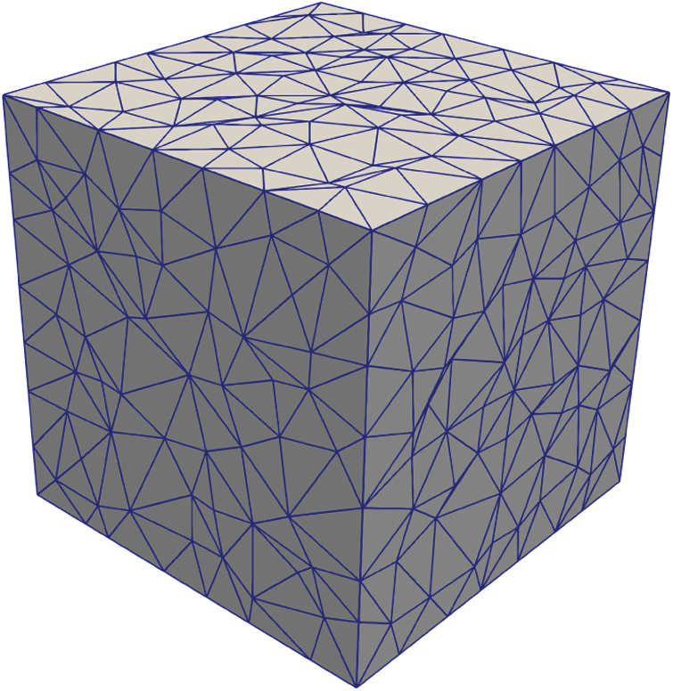
Figure 14: The geometry of the cube with distorted finite element meshes
Fig. 15 shows the deformed shapes of the cube for DOLFIN software with MINI element, cell-based smoothing, face-based smoothing, edge-based smoothing, and the bubble-enhanced face- and edge-based smoothing approaches.
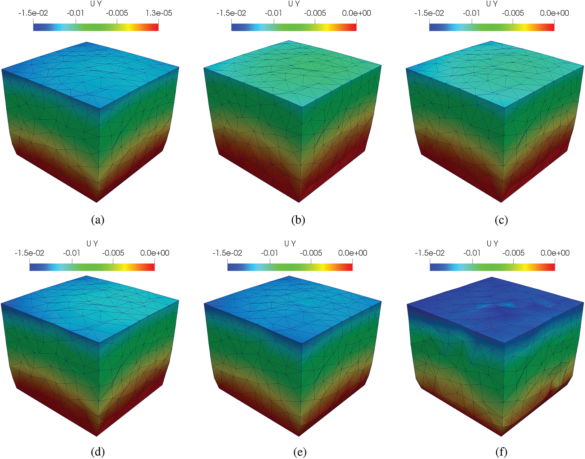
Figure 15: Deformed shapes of the cube. (a) MINI element, (b) cell-based S-FEM T4, (c) face-based S-FEM T4, (d) edge-based S-FEM T4, (e) face-based S-FEM with bubble enrichment and (f) edge-based S-FEM with bubble enrichment
The pseudo-analytical solution obtained with DOLFIN software using MINI element with regular fine meshes. The convergence of displacement and strain energy errors and the detailed relative errors of displacement and strain energy for the mesh distortion problem can be found in Fig. 16 and Tab. 5, respectively. MINI element gives lower strain relative error but higher displacement error than cell-based, face-based and edge-based smoothing methods. This result shows that the MINI element effectively handles volumetric locking in nearly-incompressible media, compared to normal smoothed-strain approaches. However, MINI element is still suffered from highly distorted meshes. The bubble-enriched-FS-FEM shows the improvement of accuracy in the both displacement and strain energy rather than the standard FS-FEM: around 20% of improvement in displacement and 85% of improvement in strain energy. Moreover, bFS-FEM provides more accurate result in strain energy although displacement relative error is slightly higher than ES-FEM, reducing almost half of strain energy error. A remarkable result we obtain from this problem is the performance of bubble-enhanced face-based smoothing approach is rather better than ES-FEM for the combined mesh distortion and nearly-incompressible problem.
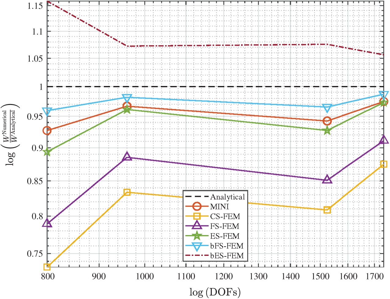
Figure 16: The convergence of the strain energy for the cube
Table 5: Strain energy and displacement relative error for the cube
In this work, the strain-smoothed finite element approaches were extended to the problem of three-dimensional hyperelasticity. On each smoothing domain, the smoothed deformation gradients are constructed, allowing expressions for the smoothed strain-displacement matrix, the smoothed tangent stiffness matrix and the smoothed internal force vector to be obtained. The cubic bubble enrichment function for the 3D face-based and the edge-based strain smoothing methods is also introduced. The proposed bubble function is straightforwardly implemented into the existing smoothed-strain framework.
The proposed S-FEMs and their bubble-enhancement are examined by numerical benchmark tests to evaluate their immunity to volumetric locking and mesh distortion. Comparisons are made with solutions obtained by DOLFIN using the well-known MINI element. Quasi-incompressible media,
From the results carried out in numerical tests, the following conclusions are obtained:
• the behaviour of CS-FEM is similar to FEM in quasi-incompressible media; that, the cell-based strain smoothing method is not able to avoid the over-estimation of stiffness;
• the accuracy and stability of the edge-based and node-based smoothed-strain approaches are problem-dependent, which means ES-FEM and NS-FEM occasionally fail to solve the problem; and
• the bubble-enrichment in the framework of the strain smoothing approach shows more accurate and reliable results, especially in the quasi-incompressible case, than do to the standard S-FEM.
A notable issue of the instability of 3D-extended NS-FEM and ES-FEM is found through certain numerical tests, for which those methods either failed to converge or produced substantially higher error. FS-FEM, especially the bubble-enhancement version, however, provides a very stable solution and relatively accurate results compared with FEM or even other S-FEMs. Because the concept behind the face-based smoothing method has been geometrically derived from the 2D edge-based S-FEM, bFS-FEM is more reliable than the direct transfer of ES-FEM and NS-FEM into three dimensions.
Overall, the bubble-enriched face-based strain-smoothed approach with low order tetrahedral cells provides a computationally efficient, yet stable and accurate solution for large deformation quasi-incompressible problems.
In future work, we plan to integrate the proposed method with the efficient total Lagrangian Explicit Dynamics (TLED) algorithm [33] which should further reduce solution times, especially when deployed on massively parallel GPU hardware [33].
1https://fenicsproject.org/docs/dolfin/2018.1.0/python/demos.html
2ESCO RTS Co., Ltd., (https://enrtech.co.kr/en/).
Funding Statement: Changkye Lee and Jurng-Jae Yee would like to thank the support by Basic Science Research Program through the National Research Foundation (NRF) funded by Korea through Ministry of Education (No. 2016R1A6A1A03012812).
Conflicts of Interest: The authors declare that they have no conflicts of interest to report regarding the present study.
1. Belytschko, T., Moran, B., Liu, W. (2000). Nonlinear finite element for continua and structures. Hoboken, New Jersey, United States: John Wiley & Sons, Ltd. [Google Scholar]
2. Remacle, J., Lambrechts, J. (2016). Fast and robust mesh generation on the sphere-application to coastal domains. Procedia Engineering, 163(1), 20–32. DOI 10.1016/j.proeng.2016.11.011. [Google Scholar] [CrossRef]
3. Rabczuk, T., Belytschko, T. (2007). A three-dimensional large deformation meshfree method for arbitrary evolving cracks. Computer Methods in Applied Mechanics and Engineering, 196(29, 30), 2777–2799. DOI 10.1016/j.cma.2006.06.020. [Google Scholar] [CrossRef]
4. Liu, G., Dai, K., Nguyen, T. (2007). A smoothed finite element method for mechanics problems. Computational Mechanics, 39(6), 859–877. DOI 10.1007/s00466-006-0075-4. [Google Scholar] [CrossRef]
5. Liu, G., Nguyen, T., Dai, K., Lam, K. (2007). Theoretical aspects of the smoothed finite element method (SFEM). International Journal of Numerical Methods in Engineering, 71(8), 902–930. DOI 10.1002/nme.1968. [Google Scholar] [CrossRef]
6. Liu, G., Nguyen-Xuan, H., Nguyen-Thoi, T. (2010). A theoretical study on the smoothed fem (SFEM) models: Properties, accuracy and convergence rates. International Journal for Numerical Methods in Engineering, 84(10), 1222–1256. DOI 10.1002/nme.2941. [Google Scholar] [CrossRef]
7. Nguyen-Thoi, T., Liu, G., Lam, K., Zhang, G. (2009). A face-based smoothed finite element method (FS-FEM) for 3D linear and geometrically non-linear solid mechanics problems using 4-node tetrahedral elements. International Journal for Numerical Methods in Engineering, 78(3), 324–353. DOI 10.1002/nme.2491. [Google Scholar] [CrossRef]
8. Nguyen-Thoi, T., Liu, G., Vu-Do, H., Nguyen-Xuan, H. (2009). A face-based smoothed finite element method (FS-FEM) for visco-elastoplastic analyses of 3D solids using tetrahedral mesh. Computer Methods in Applied Mechanics and Engineering, 198(41–44), 3479–3498. DOI 10.1016/j.cma.2009.07.001. [Google Scholar] [CrossRef]
9. Nguyen-Thoi, T., Vu-Do, H., Rabczuk, T., Ngueyn-Xuan, H. (2010). A node-based smoothed finite element method (NS-FEM) for upper bound solution to visco-elastoplastic analyses of solids using triangular and tetrahedral meshes. Computers Methods in Applied Mechanics and Engineering, 199(45–48), 3005–3027. DOI 10.1016/j.cma.2010.06.017. [Google Scholar] [CrossRef]
10. Cazes, F. M. G. (2013). An edge-based smoothed finite element method for 3D analysis of solid mechanics problems. International Journal for Numerical Methods in Engineering, 94(8), 715–739. DOI 10.1002/nme.4472. [Google Scholar] [CrossRef]
11. He, Z., Liu, G., Zhong, Z., Zhang, G. (2010). Coupled analysis of 3D structural-acoustic problems using the edge-based smoothed finite element method/finite element method. Finite Elements in Analysis and Design, 46(12), 1114–1121. DOI 10.1016/j.finel.2010.08.003. [Google Scholar] [CrossRef]
12. Li, W., Chai, Y., Lei, M., Liu, G. (2014). Analysis of coupled structural acoustic problems based on the smoothed finite element method (S-FEM). Engineering Analysis with Boundary Elements, 42(4), 84–91. DOI 10.1016/j.enganabound.2013.08.009. [Google Scholar] [CrossRef]
13. Feng, S., Cui, X., Li, G. (2013). Transient thermal mechanical analyses using a face-based smoothed finite element method (FS-FEM). International Journal of Thermal Sciences, 74(10–11), 95–103. DOI 10.1016/j.ijthermalsci.2013.07.002. [Google Scholar] [CrossRef]
14. Cui, X., Feng, S., Li, G. (2014). A cell-based smoothed radial point interpolation method (CS-RPIM) for heat transfer analysis. Engineering Analysis with Boundary Elements, 40(6–7), 147–153. DOI 10.1016/j.enganabound.2013.12.004. [Google Scholar] [CrossRef]
15. Wu, S., Liu, G., Zhang, H., Xu, X., Li, Z. (2009). A node-based smoothed point interpolation method (NS-PIM) for three-dimensional heat transfer problems. International Journal of Thermal Sciences, 48(7), 1367–1376. DOI 10.1016/j.ijthermalsci.2008.10.010. [Google Scholar] [CrossRef]
16. Wu, S., Liu, G., Cui, X., Nguyen, T., Zhang, G. (2010). An edge-based smoothed point interpolation method (ES-PIM) for heat transfer analysis of rapid manufacturing system. International Journal of Heat and Mass Transfer, 53(9–10), 1938–1950. DOI 10.1016/j.ijheatmasstransfer.2009.12.062. [Google Scholar] [CrossRef]
17. Natarajan, S., Bordas, S., Ooi, E. (2015). Virtual and smoothed finite elements: A connection and its application to polygonal/polyhedral finite element methods. International Journal for Numerical Methods in Engineering, 104(13), 1173–1199. [Google Scholar]
18. Zheng, W., Liu, G., Kitamura, Y., Nguyen-Xuan, H. (2013). A three-dimensional es-fem for fracture mechanics problems in elastic solids. Engineering Fracture Mechanics, 114(4), 127–150. DOI 10.1016/j.engfracmech.2013.10.017. [Google Scholar] [CrossRef]
19. Jiang, C., Zhang, Z., Han, X., Liu, G. (2014). Selective smoothed finite element methods for extremely large deformation of anisotropic incompressible bio-tissues. International Journal for Numerical Methods in Engineering, 99(8), 587–610. DOI 10.1002/nme.4694. [Google Scholar] [CrossRef]
20. Jiang, C., Liu, G., Han, X., Zhang, Z. (2015). A smoothed finite element method for analysis of anisotropic large deformation of passive rabbit ventricles in diastole. International Journal for Numerical Methods in Biomedical Engineering, 31(1), e02697. DOI 10.1002/cnm.2697. [Google Scholar] [CrossRef]
21. Liu, G., Nguyen, T. (2010). Smoothed finite element methods. Boca Raton, Florida, United States: CRC Press. [Google Scholar]
22. Lee, C., Angela Mihai, L., Hale, J., Kerfriden, P., Bordas, S. (2017). Strain smoothing for compressible and nearly-compressible finite elasticity. Computers & Structures, 182(6), 540–555. DOI 10.1016/j.compstruc.2016.05.004. [Google Scholar] [CrossRef]
23. Ong, T., Heaney, C., Lee, C., Nguyen-Xuan, H., Liu, G. (2015). On stability, convergence and accuracy of bES-FEM and bFS-FEM for nearly incompressible elasticity. Computer Methods in Applied Mechanics and Engineering, 285, 315–345. DOI 10.1016/j.cma.2014.10.022. [Google Scholar] [CrossRef]
24. Bordas, S., Rabczuk, T., Nguyen-Xuan, H., Nguyen, V., Natarajan, S. et al. (2010). Strain smoothing in FEM and XFEM. Computers & Structures, 88(23–24), 1419–1443. DOI 10.1016/j.compstruc.2008.07.006. [Google Scholar] [CrossRef]
25. Nguyen-Xuan, H. (2008). A strain smoothing method in finite element for structural analysis (Ph.D. Thesis). University of Liege. [Google Scholar]
26. Lee, C. (2015). Gradient smoothing in finite elasticity: Near-incompressibility. (Ph.D. Thesis). Cardiff University. [Google Scholar]
27. Nguyen-Xuan, H., Liu, G. (2013). An edge-based smoothed finite element method softened with a bubble function (bES-FEM) for solid mechanics problem. Computers & Structures, 128(4), 14–30. DOI 10.1016/j.compstruc.2013.05.009. [Google Scholar] [CrossRef]
28. Jin, H., Lu, W., Scheffel, S., Hinnerichs, T., Neilsen, M. (2007). Full-field characterization of mechanic behavior of polyurethane foams. International Journal of Solids and Structures, 44(21), 6930–6944. DOI 10.1016/j.ijsolstr.2007.03.018. [Google Scholar] [CrossRef]
29. Taylor, Z., Cheng, M., Ourselin, S. (2008). High-speed non-linear finite element analysis for surgical simulation using graphics processing units. IEEE Transactions on Medical Imaging, 27(5), 650–663. DOI 10.1109/TMI.2007.913112. [Google Scholar] [CrossRef]
30. Logg, A., Wells, G. (2010). DOLFIN: Automated finite element computing. ACM Transactions on Mathematical Software, 37(2), 1–28. DOI 10.1145/1731022.1731030. [Google Scholar] [CrossRef]
31. Logg, A., Wells, G., Hake, J. (2012). DOLFIN: A C++/Python finite element library. Berlin, Germany: Springer. [Google Scholar]
32. Arnold, D., Brezzi, F., Fortin, M. (1984). A stable finite element for the stokes equations. Calcolo, 21(4), 337–344. DOI 10.1007/BF02576171. [Google Scholar] [CrossRef]
33. Miller, K., Joldes, G., Lance, D., Wittek, A. (2007). Total lagrangian explicit dynamics finite element algorithm for computing soft tissue deformation. Communications in Numerical Methods in Engineering, 23(2), 121–134. DOI 10.1002/cnm.887. [Google Scholar] [CrossRef]
 | This work is licensed under a Creative Commons Attribution 4.0 International License, which permits unrestricted use, distribution, and reproduction in any medium, provided the original work is properly cited. |