Engineering & Sciences
| Computer Modeling in Engineering & Sciences |
DOI: 10.32604/cmes.2021.015259
ARTICLE
The Nonlinear Coupling of Oscillating Bubble and Floating Body with Circular Hole
College of Shipbuilding Engineering, Harbin Engineering University, Harbin, Heilongjiang, China
*Corresponding Author: Yunlong Liu. Email: yunlong_liu@hrbeu.edu.cn
Received: 05 December 2020; Accepted: 08 February 2021
Abstract: The fluid-structure interaction of the oscillating bubble and floating body with circular hole is essentially the nonlinear coupling problem among the incomplete movable boundary, free surface and bubble. This problem is particularly complicated in bubble dynamics. Combined with the volume of fluid method, the Eulerian finite element method is employed to deal with the fluid movement. Based on the improved penalty immersed boundary method, the transient axisymmetric numerical model is established in this paper, considering the fluid-structure interaction effect. The results of simulation are consistent with those of the electric discharge bubble experiment and explosion experiment. Subsequently, considering the influence of the hole size, floating body density, explosive location, and buoyancy, this complex fluid-structure interaction problem is analyzed systematically. Through numerical simulation, we get some new conclusions. When the radius of the hole Rh less than the maximum radius of the oscillating bubble, the changes in the whole system are incredibly intense, and the free surface crushing will emerge. The energy of the bubble acts more on the radial direction of the floating body, when the explosive location parameter is small. When the floating body has the same density as the water, the multiple spike skirt is displayed vividly. And the buoyancy of fluid can produce a lifting effect on the floating body.
Keywords: Bubble dynamics; fluid-structure interaction; Eulerian finite element method
Since the last century, bubble dynamics [1–4] has been receiving increasing attention from researchers, and it has been widely used in resource detection with air-gun array [5], underwater explosion [2,6–8], and biomedical fields [9]. With the rapid development of weapons and equipment technology, the damage caused by the underwater explosion of ships and marine structures has become more severe, which seriously restricts the vitality of vessels and marine systems. When the underwater explosion occurs near the marine structures, the generated shockwave will cause the marine structures to rupture. After the hole is created, the air inside the structures will bring about the appearance of the free surface. Simultaneously, generated bubbles will further affect the vitality of structures. The structural deformation induced by pulsating pressure, the further impact of the bubble jet load on the structures, and the water hump which causes water to flow into the cabin are all we should consider. Essentially, they are nonlinear coupling problems among the incomplete moving boundary, free surface and bubble. Therefore, to master the mechanics of the entire underwater explosion process, it is imperative to research the fluid-structure interaction between bubbles and broken structures. In recent years, many researchers have conducted extensive researches on related issues [10], but there are relatively few references considering the fluid-structure interaction effect.
Theoretical analysis [11], model testing [1,2,12–14], and numerical analysis [13,15–20] are three main methods for studying the underwater explosion problems. Extensive researches have been accomplished on bubble dynamics. In the early stage of research, theoretical research was the first to appear. The prediction model of the underwater explosion bubble was established by Geers et al. [11], who aim to solve spherical bubble problems. For nonlinear coupling problems under complex boundaries, theoretical analysis is arduous. With the development of the boundary element method [19–21], many researchers began to study non-spherical bubbles. However, the effect of the boundary element method to solve complicated engineering problems is not ideal. Because it requires many specific numerical processing skills. Therefore, researchers began to find more general numerical methods to study shock waves and bubbles, including the finite volume method [22], discontinuous Galerkin method [23], and smoothed particle hydrodynamics method [24]. Li et al. [25] used the finite volume method to research the bursting behaviors of bubble near free surface. Wang et al. [18] utilized the discontinuous Galerkin method to research the characteristic of pressure produced by the jet penetration, considering the compressibility of the fluid. Various numerical methods have deepened people’s understanding towards the underwater explosion problems. At present, relatively few articles have refined and full-cycle simulation, considering the movement of the structures under the ultra-close boundary conditions. Simultaneously, experimental research is also fundamental and can verify numerical algorithms. Cui et al. [1,14] did some basic rational experiments in this field.
Nowadays, numerical methods are continually evolving. The Eulerian finite element method is good at solving transient problems related to the large deformation of structures. This method was first established by Benson. Then he gave the main framework of the Eulerian finite element method, and proposed a brand-new advection approach for the node-centered parameters like momentum [26–29]. Liu et al. [30–32] applied it to the research of bubble dynamics, and obtained good numerical results. Besides, the volume of fluid method (VOF) is a mature interface capture method [22,33–36]. It can simulate the fracture of the free surface in solving the hydrodynamic problems. This method has been embedded in many commercial software, and has achieved good results.
The immersed boundary method was initially proposed by researchers to simulate the flow of blood in the heart [37,38], and this method is widely used over the years [39–41]. Fai et al. [42] proposed the lubrication format of the immersed boundary method. Yuan et al. [41] applied the immersed boundary method to deal with the compressible viscous fluid flow. Afra et al. [43] combined the immersed boundary method with the lattice Boltzmann method to establish a reliable numerical solution model. Kim et al. applied the penalty immersed boundary method for the research of a rigid body in fluid, which proved the penalty immersed boundary was quite significant. By comparison, the penalty immersed boundary method is a relatively accurate and stable processing method for fluid-structure interaction problems [44,45].
To further study the nonlinear coupling mechanism of the underwater explosion, the fluid-structure interaction model between the oscillating bubble and floating body with circular hole is established based on the Eulerian finite element method, the VOF method, the monotonic upwind scheme for conservation laws (MUSCL), and the penalty immersed boundary method. This paper focus on the basic research in engineering problems, so the physical model has been simplified to the axisymmetric model. A floating rigid body with a circular hole is initially placed at the free surface to represent the broken part of ships and marine structures, affected by the underwater explosion. Then, an oscillating bubble is beneath the hole and interacts with the floating structure above, as showed in Fig. 1. d is the distance from the free surface to the explosive location, Rh is the hole radius of the floating body, Rw is the radical width of the floating body, At is the axial thickness of the floating body, Rm represents the maximum radius of the bubble which can be used to calculate the initial conditions, and the origin of the axial coordinate is directly below the axis of symmetry.
Figure 1: The schematic diagram of the nonlinear coupling problem in this paper
This article is arranged as following. Above all, the numerical algorithm is presented, and verified by comparing the results of simulation with those of the electric discharge bubble experiment and explosion experiment. Secondly, this paper considers the influence of the hole size, the explosive location, the floating body density, and the buoyancy on the fluid-structure interaction characteristics. It shows from the results that the four factors play essential roles simultaneously. In addition, the free surface crushing, water hump, fluctuation, spike skirt, and jet penetration is carefully investigated. Finally, some conclusions are summarised.
2 Theoretical and Numerical Methods
2.1 The Eulerian Finite Element Method for Fluid Solver
The Eulerian finite element method can effectively deal with the explosion and impact problems [26,31,32], where the viscosity and thermal conduction can be ignored [12]. In this method, the governing equation for fluid is the following equation, i.e.,
where
As for mass, momentum, and energy conservation, S and
where
The Lagrangian phase is to solve Eq. (2), and it is calculated by the explicit finite element method. Then, the Galerkin equation used to solve the momentum conservation can be written as
where
where the superscript n indicates the increment number, and
and
Meanwhile, the Lagrangian phase is over, and the Eulerian phase starts. The core idea of the Eulerian phase is to achieve the transport of parameters by the VOF method and the MUSCL. The VOF method is a commonly used and effective method in computational fluid dynamics [33,34,46,47]. Its transport equation is [32]
where f is the volume fraction. The schematic diagram of the VOF method is explained in Fig. 2. Here,
where
Figure 2: The schematic diagram of the VOF method
After the Eulerian phase, the fluid equation of state is used to complete the closed solution of equations. Referring to related literature, the equation of state of the fluid is given by the Tammann equation [31], i.e.,
where
Table 1: Fluid parameters of water, air, and explosive production
2.2 The Penalty Immersed Boundary Method
For the nonlinear fluid-structure interaction problems, the processing of the fluid-structure interaction interface is complicated. The penalty immersed boundary method is used in this paper, to perform the unbalanced constraint processing of the boundary position [44,45,48,49]. In numerical simulation, this method adopts a relatively simple Cartesian grid, which avoids the divergence caused by the body-fitted grid [29]. Submission of the penalty immersed boundary method changes the governing equations of the fluid, and introduces a new additional volumetric force. Now, this paper extends the governing equation from the two-dimensional format to axisymmetric format. And the body force is the resultant force of the additional volumetric force and gravity. Continuously, Eq. (13) is the momentum equation for the fluid where the solid boundary node is located, i.e.,
The interaction force
where
Figure 3: The schematic diagram of the penalty immersed boundary method
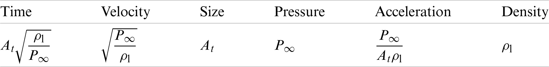
To extend the law obtained in this paper, the dimensionless processing is performed on all physical variables, which helps us understand the physical problems better. The corresponding rules are showed in Tab. 2. Here, the subscript l represents the water, At is selected as the reference length, and
Table 2: Variable scales for non-dimensionalization
In addition,
Here, fe is the volume fraction of explosive production.
3 Numerical Verification and Convergence Test
3.1 Near-Free Surface Cracking Numerical Verification
In this paper, the numerical method is verified by our electric discharge experiment. The experiment was performed in a
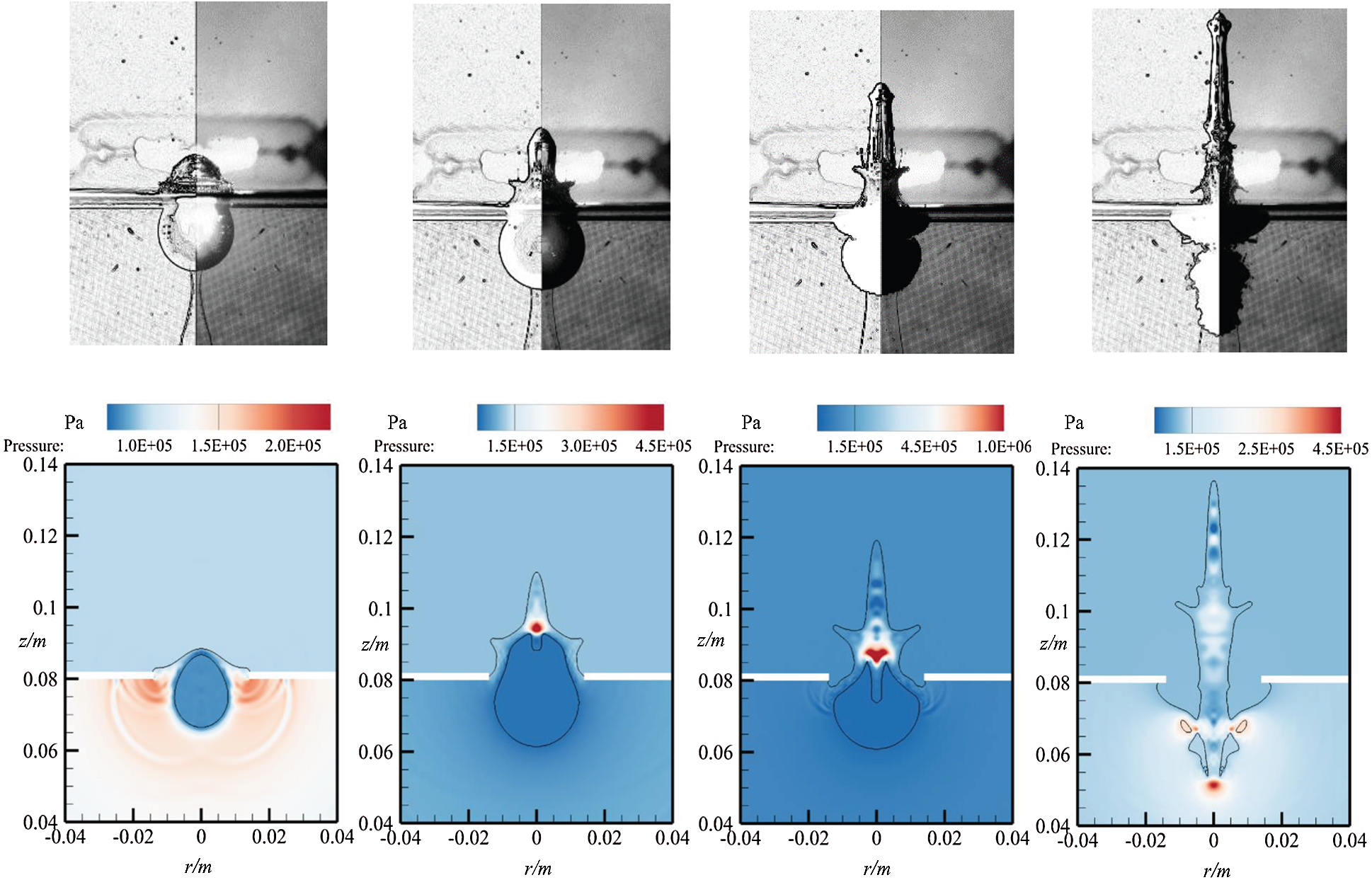
Figure 4: The experimental results diagram (above) at t = 0.60 ms, 1.40 ms, 2.80 ms, and 3.40 ms, and the numerical results diagram (below) at t = 0.52 ms, 1.32 ms, 2.75 ms, and 3.14 ms for case where Rm = 13.6 mm, d = 7.0 mm, and Rh = 15.0 mm
The numerical results are showed in Fig. 4 (below), and the boundary condition of simulation is same as that of experiment described above. In simulation, the initial conditions are obtained by the equation of bubble motion proposed by predecessors [12]. The size of the calculation domain is
In numerical simulation, the convergence of the results is a vital factor that researchers must consider. In general, the grid size has a large effect on the results of numerical simulation. When the grid size is small, the calculation efficiency is reduced. And when the grid size is large, the calculation accuracy is poor. In this paper, grid length L = 0.04At, 0.03At, and 0.02At are selected for comparison. For the case in this section, At = 1.0 m, Rw is 2.0At, Rm is 1.0At, Rh is 1.25At, d is 0.63At, and the density of the floating body is half that of water. While the grid size is 0.02At, the result has reached the corresponding convergence standard, as showed in Fig. 5. So the grid of this size is used for all cases. In calculation, the size of the calculation domain is
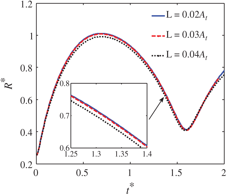
Figure 5: The time evolution of the equivalent radius curves, to study the convergence with different grid sizes
3.3 The Verification of Pressure
Flow field pressure is verified through the explosion experiment from literature [12]. The comparison diagram between the numerical and experimental results is showed in Fig. 6. The working condition is the explosion of 35 g Hexocire explosive with 3.5 m from the free surface. The pressure measuring point is located at 0.7 m from the center of the explosive, and specific experimental parameters can be obtained from the literature [12]. Standard TNT in the simulation can substitute for the Hexocirex explosive by the coefficient 1.23. In the numerical simulation, the initial TNT explosive is 43.05 g, the explosive density is
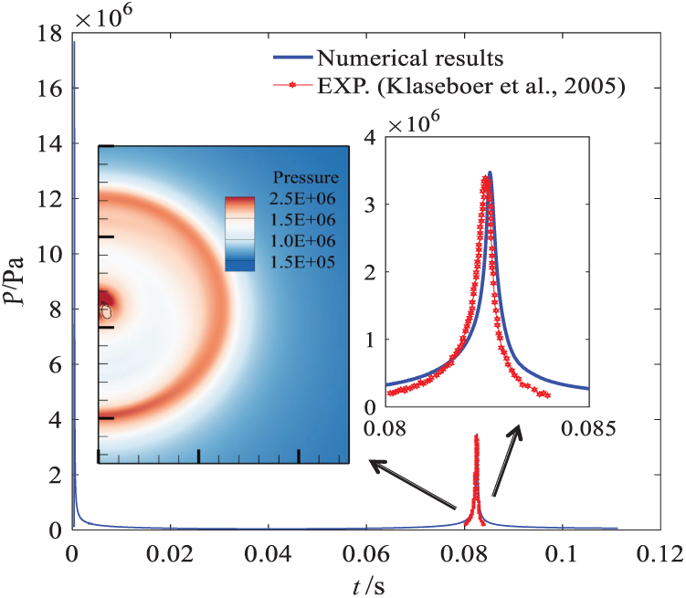
Figure 6: The comparison diagram between the numerical results and experimental results [12]
4.1 Basic Features of Interaction
In this work, the nonlinear coupling characteristics will be researched systematically. The differences in the hole size, floating body density, and explosive location can affect the corresponding physical process. So the effects of these factors are analyzed in detail and qualitatively. In the last section of this chapter, the buoyancy that account for the scale effect is also discussed. In order to analyze the different factors through the method of controlling variables, a reference case is selected firstly. And the parameters of the reference case have been described in Section 3.2.
Figure 7: The diagram of free surface and flow field pressure at t* = 0.016, 0.41, 0.83, 1.30, 1.67, and 2.10 for case where
It can be seen from Fig. 7 that the bubble gradually expands to the maximum bubble radius, from the initial time to t* = 0.41, which is the result of bubble internal pressure continuously propagates outward. When the bubble expands to a certain volume, a jet away from the free surface is visible at t* = 0.83, due to the induction of the free surface. And there is a small high-pressure zone above the jet. The jet continuously moves downward, until the bubble is broken at t* = 1.30. With the bubble breaking, a high pressure temporarily propagates outward once again. At both moments of t* = 1.67 and 2.10, the bubble exhibits compressible effects. The fluctuation and spike skirt phenomenon occur at the free surface. Throughout the physical process, the energy generated by the bubble acts on the floating body, which manifests itself as the oscillation of a floating body. The floating body movement is accompanied by the expansion, collapsing, and rebound of the bubble, as showed in Fig. 8. In addition, the results with or without damping are compared, and it can be seen that the damping term can effectively reduce the numerical oscillation.
Figure 8: The floating body axial velocity curve for case where
4.2 Influence of the Hole Size
The impact pressure of the transient shock wave will cause the damage of structures, which will emerge a few holes with different sizes. Different hole sizes will change the characteristics of bubble motion, so it is of great significance to study the influence of the hole size. In this paper, compared with the reference case in Section 4.1, the hole parameter
Figure 9: The free surface curves at typical moments for cases with different hole sizes. The induction of structure, cavity, and crushing of free surface is showed in above figure
The effect of hole size reflects the coupling between the bubble and solid boundary. It can be seen from Fig. 9 that the size of the hole has a significant influence on the changes of the free surface. Compared with the reference case, when the radius of the hole Rh less than the maximum radius of the oscillating bubble, the dynamic effect of the broken floating body on the bubble embodies significantly. At t* = 0.52, it can be seen that the structure can induce the deformation of bubble, resulting in the no-smooth appearance of the bubble. At t* = 1.28, the air above the system rushes into the sides of the hole, and the cavity appears when
The influence of the hole size is effectively discussed in this work by Fig. 10. It can be seen from the bubble equivalent radius diagram that when
Figure 10: The curves of the bubble equivalent radius (left) and floating body velocity (right) with different hole radiuses
4.3 Influence of the Floating Body Density
In accordance with the different floating body density, the floating body has various circumstances on the free surface, including floating and suspension. The different circumstances of the floating body will form different boundary conditions, which will induce some new physical features. In this paper, the density parameter
Figure 11: The diagram of free surface and flow field pressure at t* = 0.24, 0.62, 0.96, 1.32, 1.61, and 2.06 for case where
It can be seen from Fig. 11 that the floating body density owns a certain influence on the evolution of the free surface. At t* = 0.96, the climb of the free surface near the hole is more apparent. And the climbing of liquid forms a new spike skirt after t* = 1.32. The new spike skirt phenomenon is a fascinating feature for this case, which leads to multiple spike skirt in the late stage of bubble movement. The mechanism of this new spike skirt in Fig. 11 is different from that in Fig. 7. The previous spike skirt is a peculiar appearance caused by the coupling of the hole and free surface. And it occurs due to the free surface climbs to the upper surface of the floating body, during the expansion of the bubble. The last spike skirt is caused by the rebound of the bubble. Apart from this, the differences of free surface and flow field pressure between this case and the reference case are not obvious.
Through the Fig. 12, the influence of the floating body density is quantitatively analyzed in this paper. It can be seen from the bubble equivalent radius diagram that the floating body density has a small influence on the motion of the bubble. Between t* = 0.0 and 1.0, there is almost no difference in the bubble equivalent radius for the four cases. At the end of the first period of bubble motion, with the decrease of the floating body density, there is a slight advance for the time of bubble jet penetration. It can be seen from the velocity diagram of the floating body that the density of the floating body has a significant influence on this process. With the decrease of the floating body density, the amplitude of floating body movement increases obviously. When the two objects are subjected to the force with same magnitude, it is known from the kinematics formula, that the acceleration of the object with a small mass is larger. That is, the corresponding movement response is more severe. In a word, a reasonable prediction is made by the fluid-structure interaction model of this paper.
Figure 12: The curves of the bubble equivalent radius (left) and floating body velocity (right) with different densities
4.4 Influence of the Explosive Location
In actual naval battle, the damaging effect of the underwater explosion is not linear with the explosive location. Therefore, it is of great significance to choose a reasonable explosive location. The fluid-structure interaction mechanism with the changes of the explosive location is analyzed in this paper. Combining the reference case in Section 4.1, the explosive location parameter d* is selected to be 1.10, 1.50, and 1.90 for numerical simulation, respectively. Then, the corresponding law is summarized. The free surface curves at typical moments for cases with different explosive locations are showed in Fig. 13.
Figure 13: The free surface curves at typical moments for cases with different explosive locations
The effect of explosive location reflects the coupling between the bubble and free surface. It can be seen from Fig. 13 that the depth of the explosive location has a great influence on the changes of the fluid field. For the reference case showed in Fig. 7, the water hump phenomenon occurs at the late stage of the bubble motion. However, as the explosive location moves away from the free surface, this phenomenon does not occur, and the free surface is relatively stable, as showed in Fig. 13. As d increases, the energy of the bubble propagating to the free surface, cannot cause the massive motion of the surface fluid. In addition, there are other several significant differences in bubble characteristics. As showed at t* = 0.31, when d* > 1.1, the bubble shape is more similar to a sphere in the early stage of the expansion process. With the change of d*, three jet modes are effectively displayed at t* = 1.80, including the counter jet, downward jet, and upward jet. As demonstrated at t* = 2.20, when the explosive location moves away from the free surface, the secondary rebound process is more intense after the bubble jet penetration.
Through Fig. 14, the influence of the explosive location is vividly displayed in this work. It can be seen from the bubble equivalent radius diagram that the explosive location has a great influence on the movement of fluid. For the oscillating bubbles with different explosive locations, there are differences in the time at which the bubble reaches the maximum radius and the jet penetration. As the distance between the bubble and free surface increases, the time is correspondingly delayed. And the change of the bubble maximum size is nonlinear due to the induction of free surface and hydrostatic pressure. It can be seen from the velocity diagram of the floating body that the broken floating body’s movement response is different, when the bubble migrates towards, and move away from the free surface. When d* = 0.63, the movement amplitude of the floating body is relatively small, which is determined by the action mechanism of the bubble energy. The energy of the bubble acts more on the radial direction of the floating body with circular hole under this condition. Finally, while d* = 1.10, d* = 1.50, and d* = 1.90, the initial floating body motion is consistent, and the floating body motion is determined by the phase of the bubble pulsation after t* = 0.75.
Figure 14: The curves of the bubble equivalent radius (left) and floating body velocity (right) with different explosive locations
4.5 Influence of the Buoyancy Effect
For small-scale bubbles, the buoyancy has less effect on them. But for the underwater explosion bubbles studied in this paper, the bubble size is very huge, and the buoyancy will have an excellent influence on the motion characteristics of bubbles. So it is reasonable to analyze the buoyancy effect through a non-dimensionless parameter. The buoyancy effect is investigated by the buoyancy parameter
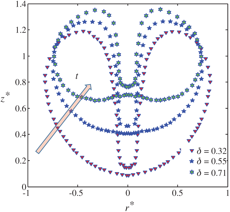
Figure 15: The diagram of non-dimensional bubble location when the jet penetration
Combining the reference case in Section 4.1,
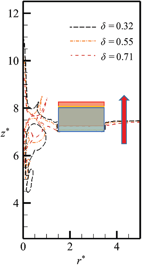
Figure 16: The free surface curves at the later stage for cases with different buoyancy parameters
In this paper, the fluid-structure interaction model of oscillating bubble and floating body with circular hole is established by combining the Eulerian finite element method, the penalty immersed boundary method, and the VOF method. This complex nonlinear problem is effectively analyzed by numerical simulation. In our work, the numerical method is verified by the electric discharge bubble experiment and explosion experiment. The effect of factors including the hole size, floating body density, explosive location, and buoyancy on the fluid-structure interaction characteristics is summarized. It is showed from the results that the four factors play essential roles simultaneously.
The effect of the hole size reflects the coupling between the bubble and solid boundary. When the radius of the hole Rh less than the oscillating bubble’s maximum radius the changes in the whole system are incredibly intense, and the free surface crushing will emerge. When
Funding Statement: The National Key R and D Program of China (2018YFC0308900), the National Natural Science Foundation of China (Grant No. 51879050), the Industrial Technology Development Program (Grant No. JCKY2018604C010), and the China Postdoctoral Science Foundation (Grant Nos. 2016M600244, 2018T110271).
Conflicts of Interest: The authors declare that they have no conflicts of interest to report regarding the present study.
1. Cui, P., Zhang, A. M., Wang, S., Khoo, B. C. (2018). Ice breaking by a collapsing bubble. Journal of Fluid Mechanics, 841, 287–309. DOI 10.1017/jfm.2018.63. [Google Scholar] [CrossRef]
2. Song, G., Chen, Z. Y., Long, Y., Zhong, M. S., Wu, J. Y. (2017). Experimental and numerical investigation of the centrifugal model for underwater explosion shock wave and bubble pulsation. Ocean Engineering, 142(4), 523–531. DOI 10.1016/j.oceaneng.2017.04.035. [Google Scholar] [CrossRef]
3. Pearson, A., Cox, E., Blake, J. R., Otto, S. R. (2004). Bubble interactions near a free surface. Engineering Analysis with Boundary Elements, 28(4), 295–313. DOI 10.1016/S0955-7997(03)00079-1. [Google Scholar] [CrossRef]
4. Wang, S. P., Zhang, A. M., Liu, Y. L., Zhang, S., Cui, P. (2018). Bubble dynamics and its applications. Journal of Hydrodynamics, 30(6), 975–991. DOI 10.1007/s42241-018-0141-3. [Google Scholar] [CrossRef]
5. Zhang, S., Wang, S. P., Zhang, A. M., Cui, P. (2018). Numerical study on motion of the air-gun bubble based on boundary integral method. Ocean Engineering, 154(4), 70–80. DOI 10.1016/j.oceaneng.2018.02.008. [Google Scholar] [CrossRef]
6. Ming, F. R., Zhang, A. M., Xue, Y. Z., Wang, S. P. (2016). Damage characteristics of ship structures subjected to shockwaves of underwater contact explosions. Ocean Engineering, 117(9–10), 359–382. DOI 10.1016/j.oceaneng.2016.03.040. [Google Scholar] [CrossRef]
7. Tian, Z., Liu, Y., Wang, S., Zhang, A. M., Kang, Y. (2019). Dynamic response of floating body subjected to underwater explosion bubble and generated waves with 2D numerical model. Computer Modeling in Engineering & Sciences, 118(2), 397–423. DOI 10.31614/cmes.2019.04419. [Google Scholar] [CrossRef]
8. Zhang, N., Zong, Z., Zhang, W. (2014). Dynamic response of a surface ship structure subjected to an underwater explosion bubble. Marine Structures, 35(l), 26–44. DOI 10.1016/j.marstruc.2013.11.001. [Google Scholar] [CrossRef]
9. Gutiérrez-Prieto, Á., de Icaza-Herrera, M., Loske, A. M., Castao-Tostado, E. (2019). Kriging model to study the dynamics of a bubble subjected to tandem shock waves as used in biomedical applications. Ultrasonics, 91, 10–18. DOI 10.1016/j.ultras.2018.07.005. [Google Scholar] [CrossRef]
10. Liu, Y. L., Wang, S. P., Zhang, A. M. (2016). Interaction between bubble and air-backed plate with circular hole. Physics of Fluids, 28(6), 62105. DOI 10.1063/1.4953010. [Google Scholar] [CrossRef]
11. Geers, T. L., Hunter, K. S. (2002). An integrated wave-effects model for an underwater explosion bubble. The Journal of the Acoustical Society of America, 111(4), 1584–1601. DOI 10.1121/1.1458590. [Google Scholar] [CrossRef]
12. Klaseboer, E., Hung, K. C., Wang, C., Wang, C. W., Khoo, B. C. et al. (2005). Experimental and numerical investigation of the dynamics of an underwater explosion bubble near a resilient/rigid structure. Journal of Fluid Mechanics, 537, 387–413. DOI 10.1017/S0022112005005306. [Google Scholar] [CrossRef]
13. Liu, N. N., Wu, W. B., Zhang, A. M., Liu, Y. L. (2017). Experimental and numerical investigation on bubble dynamics near a free surface and a circular opening of plate. Physics of Fluids, 29(10), 107102. DOI 10.1063/1.4999406. [Google Scholar] [CrossRef]
14. Zhang, A. M., Cui, P., Cui, J., Wang, Q. X. (2015). Experimental study on bubble dynamics subject to buoyancy. Journal of Fluid Mechanics, 776, 137–160. DOI 10.1017/jfm.2015.323. [Google Scholar] [CrossRef]
15. Chen, G. Q., Zhang, A. M., Huang, X. (2018). On the interaction between bubbles and the free surface with high density ratio 3D lattice boltzmann method. Theoretical and Applied Mechanics Letters, 8(4), 252–256. DOI 10.1016/j.taml.2018.04.006. [Google Scholar] [CrossRef]
16. Hsu, C. Y., Liang, C. C., Nguyen, A. T., Teng, T. L. (2014). A numerical study on the underwater explosion bubble pulsation and the collapse process. Ocean Engineering, 81(4), 29–38. DOI 10.1016/j.oceaneng.2014.02.018. [Google Scholar] [CrossRef]
17. Li, S., Khoo, B. C., Zhang, A. M., Wang, S. (2018). Bubble-sphere interaction beneath a free surface. Ocean Engineering, 169(22), 469–483. DOI 10.1016/j.oceaneng.2018.09.032. [Google Scholar] [CrossRef]
18. Wang, L. K., Zhang, Z. F., Wang, S. P. (2016). Pressure characteristics of bubble collapse near a rigid wall in compressible fluid. Applied Ocean Research, 59(2), 183–192. DOI 10.1016/j.apor.2016.06.003. [Google Scholar] [CrossRef]
19. Zhang, A. M., Wu, W. B., Liu, Y. L., and Wang, Q. X. (2017). Nonlinear interaction between underwater explosion bubble and structure based on fully coupled model. Physics of Fluids, 29(8), 082111. DOI 10.1063/1.4999478. [Google Scholar] [CrossRef]
20. Zong, Z., Wang, J. X., Zhou, L., Zhang, G. Y. (2015). Fully nonlinear 3D interaction of bubble dynamics and a submerged or floating structure. Applied Ocean Research, 53(7), 236–249. DOI 10.1016/j.apor.2015.09.011. [Google Scholar] [CrossRef]
21. Li, S., Han, R., Zhang, A. M., Wang, Q. X. (2016). Analysis of pressure field generated by a collapsing bubble. Ocean Engineering, 117, 22–38. DOI 10.1016/j.oceaneng.2016.03.016. [Google Scholar] [CrossRef]
22. Li, T., Wang, S., Li, S., Zhang, A. M. (2018). Numerical investigation of an underwater explosion bubble based on FVM and VOF. Applied Ocean Research, 74, 49–58. DOI 10.1016/j.apor.2018.02.024. [Google Scholar] [CrossRef]
23. Ge, L., Zhang, A. M., Wang, S. P. (2020). Investigation of underwater explosion near composite structures using a combined RKDG-FEM approach. Journal of Computational Physics, 404, 23. DOI 10.1016/j.jcp.2019.109113. [Google Scholar] [CrossRef]
24. Wang, P., Zhang, A. M., Ming, F., Sun, P., Cheng, H. (2019). A novel non-reflecting boundary condition for fluid dynamics solved by smoothed particle hydrodynamics. Journal of Fluid Mechanics, 860, 81–114. DOI 10.1017/jfm.2018.852. [Google Scholar] [CrossRef]
25. Li, T., Zhang, A. M., Wang, S. P., Li, S., Liu, W. T. (2019). Bubble interactions and bursting behaviors near a free surface. Physics of Fluids, 31(4), 42104. DOI 10.1063/1.5088528. [Google Scholar] [CrossRef]
26. Benson, D. J. (1992). Computational methods in lagrangian and eulerian hydrocodes. Computer Methods in Applied Mechanics and Engineering, 99(2), 235–394. DOI 10.1016/0045-7825(92)90042-I. [Google Scholar] [CrossRef]
27. Benson, D. J. (1992). Momentum advection on a staggered mesh. Journal of Computational Physics, 100(1), 143–162. DOI 10.1016/0021-9991(92)90316-Q. [Google Scholar] [CrossRef]
28. Benson, D. J. (2008). Momentum advection on unstructured staggered quadrilateral meshes. International Journal for Numerical Methods in Engineering, 75(13), 1549–1580. DOI 10.1002/nme.2310. [Google Scholar] [CrossRef]
29. Benson, D. J., Okazawa, S. (2004). Contact in a multi-material eulerian finite element formulation. Computer Methods in Applied Mechanics and Engineering, 193(39), 4277–4298. DOI 10.1016/j.cma.2003.12.061. [Google Scholar] [CrossRef]
30. He, M., Zhang, A. M., Liu, Y. L. (2020). Prolonged simulation of near-free surface underwater explosion based on eulerian finite element method. Theoretical and Applied Mechanics Letters, 10(1), 16–22. DOI 10.1016/j.taml.2020.01.003. [Google Scholar] [CrossRef]
31. Liu, Y., Zhang, A. M., Tian, Z., Wang, S. (2018). Investigation of free-field underwater explosion with eulerian finite element method. Ocean Engineering, 166(1), 182–190. DOI 10.1016/j.oceaneng.2018.08.001. [Google Scholar] [CrossRef]
32. Tian, Z. L., Liu, Y. L., Zhang, A. M., Wang, S. P. (2018). Analysis of breaking and re-closure of a bubble near a free surface based on the eulerian finite element method. Computers & Fluids, 170, 41–52. DOI 10.1016/j.compfluid.2018.04.028. [Google Scholar] [CrossRef]
33. Albadawi, A., Donoghue, D. B., Robinson, A. J., Murray, D. B., Delauré, Y. M. C. (2014). On the assessment of a VOF based compressive interface capturing scheme for the analysis of bubble impact on and bounce from a flat horizontal surface. International Journal of Multiphase Flow, 65, 82–97. DOI 10.1016/j.ijmultiphaseflow.2014.05.017. [Google Scholar] [CrossRef]
34. Denner, F., van Wachem, B. G. M. (2014). Compressive vof method with skewness correction to capture sharp interfaces on arbitrary meshes. Journal of Computational Physics, 279, 127–144. DOI 10.1016/j.jcp.2014.09.002. [Google Scholar] [CrossRef]
35. Gopala, V. R., van Wachem, B. G. M. (2008). Volume of fluid methods for immiscible-fluid and free-surface flows. Chemical Engineering Journal, 141(1), 204–221. DOI 10.1016/j.cej.2007.12.035. [Google Scholar] [CrossRef]
36. Hirt, C. W., Nichols, B. D. (1981). Volume of fluid (VOF) method for the dynamics of free boundaries. Journal of Computational Physics, 39(1), 201–225. DOI 10.1016/0021-9991(81)90145-5. [Google Scholar] [CrossRef]
37. Peskin, C. S. (1972). Flow patterns around heart valves: A numerical method. Journal of Computational Physics, 10(2), 252–271. DOI 10.1016/0021-9991(72)90065-4. [Google Scholar] [CrossRef]
38. Peskin, C. S. (1977). Numerical analysis of blood flow in the heart. Journal of Computational Physics, 25(3), 220–252. DOI 10.1016/0021-9991(77)90100-0. [Google Scholar] [CrossRef]
39. Sotiropoulos, F., Yang, X. (2014). Immersed boundary methods for simulating fluid structure interaction. Progress in Aerospace Sciences, 65, 1–21. DOI 10.1016/j.paerosci.2013.09.003. [Google Scholar] [CrossRef]
40. Su, S. W., Lai, M. C., Lin, C. A. (2007). An immersed boundary technique for simulating complex flows with rigid boundary. Computers & Fluids, 36(2), 313–324. DOI 10.1016/j.compfluid.2005.09.004. [Google Scholar] [CrossRef]
41. Yuan, R., Zhong, C. (2018). An immersed-boundary method for compressible viscous flows and its application in the gas-kinetic BGK scheme. Applied Mathematical Modelling, 55(4), 417–446. DOI 10.1016/j.apm.2017.10.003. [Google Scholar] [CrossRef]
42. Fai, T. G., Rycroft, C. H. (2018). Lubricated immersed boundary method in two dimensions. Journal of Computational Physics, 356(3/4), 319–339. DOI 10.1016/j.jcp.2017.11.029. [Google Scholar] [CrossRef]
43. Afra, B., Nazari, M., Kayhani, M. H., Delouei, A. A., Ahmadi, G. (2018). An immersed boundary-lattice boltzmann method combined with a robust lattice spring model for solving flow structure interaction problems. Applied Mathematical Modelling, 55, 502–521. DOI 10.1016/j.apm.2017.10.014. [Google Scholar] [CrossRef]
44. Kim, Y., Peskin, C. S. (2007). Penalty immersed boundary method for an elastic boundary with mass. Physics of Fluids, 19(5), 053103. DOI 10.1063/1.2734674. [Google Scholar] [CrossRef]
45. Kim, Y., Peskin, C. S. (2016). A penalty immersed boundary method for a rigid body in fluid. Physics of Fluids, 28(3), 033603. DOI 10.1063/1.4944565. [Google Scholar] [CrossRef]
46. Ivey, C. B., Moin, P. (2017). Conservative and bounded volume-of-fluid advection on unstructured grids. Journal of Computational Physics, 350(1), 387–419. DOI 10.1016/j.jcp.2017.08.054. [Google Scholar] [CrossRef]
47. Owkes, M., Desjardins, O. (2017). A mass and momentum conserving unsplit semi-lagrangian framework for simulating multiphase flows. Journal of Computational Physics, 332(2), 21–46. DOI 10.1016/j.jcp.2016.11.046. [Google Scholar] [CrossRef]
48. Paccou, A., Chiavassa, G., Liandrat, J., Schneider, K. (2005). A penalization method applied to the wave equation. Comptes Rendus Mécanique, 333(1), 79–85. DOI 10.1016/j.crme.2004.09.019. [Google Scholar] [CrossRef]
49. Schneider, K., Farge, M. (2002). Adaptive wavelet simulation of a flow around an impulsively started cylinder using penalisation. Applied and Computational Harmonic Analysis, 12(3), 374–380. DOI 10.1006/acha.2002.0378. [Google Scholar] [CrossRef]
50. Felippa, C. A. (1980). A family of early-time approximations for fluid-structure interaction. Journal of Applied Mechanics, Transactions ASME, 47(4), 703–708. DOI 10.1115/1.3153777. [Google Scholar] [CrossRef]
 | This work is licensed under a Creative Commons Attribution 4.0 International License, which permits unrestricted use, distribution, and reproduction in any medium, provided the original work is properly cited. |