Engineering & Sciences
| Computer Modeling in Engineering & Sciences |
DOI: 10.32604/cmes.2021.015791
ARTICLE
Flow Characteristics of Grains in a Conical Silo with a Central Decompression Tube Based on Experiments and DEM Simulations
1COFCO Research & Engineering (Zhengzhou) Co., Ltd., Zhengzhou, 450001, China
2State Key Laboratory of Structural Analysis for Industrial Equipment, Dalian University of Technology, Dalian, 116023, China
*Corresponding Author: Huinan Sun. Email: hui.nan521@163.com
Received: 31 January 2021; Accepted: 25 February 2021
Abstract: Grains are widely present in industrial productions and processing, and are stored in silos. In the silo, auxiliary structures are added to achieve efficient production. However, little effort has been devoted to the influence of the internal structure of the silo on the granular flow. In this work, a silo with a central decompression tube is studied through experimental measurements and discrete element methods. Then, the influences of the central decompression tube on the flow behavior of grains and wall pressure are analyzed. Results show that the grains are in mass flow in the silo without a central decompression tube, while the grains are in funnel flow in the silo with a central decompression tube. Moreover, regardless of whether there is a central decompression tube in the silo, the maximum pressure appears at the top of the conical silo. In the lower part of the silo, the wall pressure of the silo with a central decompression tube is lower than that of the silo without a central decompression tube. Therefore, a silo with a central decompression tube is more conducive to grain storage and discharge than a silo without a central decompression tube.
Keywords: Discrete element method; experimental measurements; central decompression tube; flow characteristics; wall pressure
The grain storage and discharge are closely related to the silos, and different types of silos have different performances. These silos can be divided into five types, including national silos, regional or inland silos, export silos, import silos, and silos for processing grain. However, safety issues occasionally occur during the discharging process, which seriously affects industrial production. This is mainly because the flow characteristics of granular materials are complicated. Silo effect [1,2], blockage [3,4], silo vibration [5,6] may cause silo collapse accidents [7] and increase the security risk. Therefore, the study of granular flow behavior in the silo and the analysis of wall pressure have important guidance for industrial productions.
The pressure distribution on the silo and the flow pattern during the filling and discharging processes have been analyzed using experimental measurement and numerical methods. Based on experimental measurements, there were two flow patterns during the discharging process, including the mass flow and funnel flow [8,9]. The discharge process of grains in the flat-bottomed silo was studied by experiments, and the discharge process included the overall flow zone, dynamic balance zone, free-fall zone, and dead zone [10]. Meanwhile, the discharge process of the granular materials consisted of a uniform motion zone, a transformation zone, a shear motion zone, and a static zone [11]. In addition, there were three distinct flow zones in the hopper, including stagnant, blockage, and transition zones. It is worth noting that the pressure distribution on the silo was different in different flow regions [12,13]. The relationship between the redirection parameter and the silo diameter in the Jassen theory was analyzed through experiments, and results showed that the redirection parameter increased as the ratio of the silo diameter to the grain diameter increased [14].
Due to the limitations of experimental measurements and finite element methods, the discrete element method (DEM) proposed in 1971 was used to analyze the flow characteristics of granular materials at the microscopic scale [15,16]. The combination of the DEM and experiments is an effective analysis method, which has been proved by practices [17]. DEM is widely used to analyze the flow pattern [18–20] and wall pressure [21]. The mathematical model of the steady-state and non-steady-state was validated by DEM simulations and experiments during the discharging process and this mathematical model was valid [22]. Based on DEM, the effects of gravity on the internal flow patterns were investigated. The angle between the stagnant zone and the sidewall was independent of gravity, and the criteria for flow pattern transition were also independent of gravity [23]. The special position of flow pattern transition during discharging of rice particles in the conical silo was presented, and the mathematical model between the silo geometry parameters and the critical height was established [24]. At present, although silos with a central decompression tube are widely used in industry, the flow pattern transition has not been studied.
In addition, the wall pressure is another important factor in the granular flow. The calculation of the wall pressure is based on the Janssen formula [25], and the wall pressure of the silo under different working conditions has been extensively studied. The stress and strain states of the silo in the loading, storage, and unloading states were measured by experiments, and the results showed that the stress states of the storage during loading and unloading were different [26]. Based on the finite element method, the wall pressure distribution, density change, velocity field, and other issues of the silo were analyzed during the discharge process, and the results showed that the overpressure phenomenon occurred when the discharge began [27]. Moreover, the discharge condition, the outlet layout, and the stress state of the silo were analyzed by changing the filling speed of grains [28]. Based on the DEM simulations, the wall pressure was investigated by varying the particle radius, the opening diameter, the hopper angle [29]. The flow characteristics of granular materials during discharge were studied when a diverter was inserted on the bottom of the silo, and the results showed that the addition of this structure reduced the wall pressure of the silo [30,31]. When the outlet is arched, the contact forces between particles in the silo were analyzed. The results showed that the normal contact force between particles near the wall was higher than that at the center of the hopper [32]. Moreover, the particle velocity and contact force during the discharging process were studied. As the external pressure increased, the normal contact force between particles and the total pressure between particles and cylindrical containers increased [33]. The wall pressure of a steel silo with an eccentric orifice was studied during the discharge process. Results showed that both inlet design and imperfection affected the pressure distribution along the silo wall [34]. However, there are few studies on the flow behaviors of granular materials in the silo with a central decompression tube, and the flow pattern and the wall pressure during the discharging process were rarely discussed. Therefore, it is necessary to further investigate the flow pattern and the wall pressure in the silo with a central decompression tube.
In this paper, the flow characteristics of granular materials in a silo with a central decompression tube were investigated using experiments and discrete element methods. Meanwhile, the numerical results were verified based on experimental results. Then, the influence of the central decompression tube on the flow pattern of granular materials and wall pressure was analyzed, and the numerical results provide guidance for the appropriate design of the silos.
2 Contact Force Model between Particles
In this study, the software EDEM is adopted to simulate the granular flow in the silo. The Hertz–Middlin non-slipping contact model is used to calculate the contact force between particles. In this contact model, the normal elastic force (
where R* is the equivalent radius of particles, obtained by 1/R* = 1/Ri + 1/Rj. Ri and Rj are the radius of particles i and j, respectively.
where Ei and Ej are the elasticity modulus of particles i and j, respectively.
The normal damping force (
where m* is the equivalent mass of grains, obtained by m* = mimj/(mi + mj). mi and mj are the mass of particles i and j, respectively.
The tangential elastic force (
where
The tangential damping force
where
The torque (
where Ri is the vector from the centroid of particle i to the contact point.
In this section, the silos with a central decompression tube are simulated using DEM, and the corresponding numerical results are compared with the experimental results. Then, the influence of the central decompression tube on the flow characteristics of grains in silos is further investigated.
In engineering applications, silos have different geometric characteristics, and some of them have mechanical structures for internal auxiliary discharging. Considering the limitations of experiments and simulations, the experimental device of the silo is shown in Fig. 1. The whole device consists of four parts, namely silo, central decompression tube, chassis, and valve. It is worth noting that the valve can be used to control the discharge process. The silo has an inner diameter of 240 mm and a height of 520 mm. The angle of the cone is 45
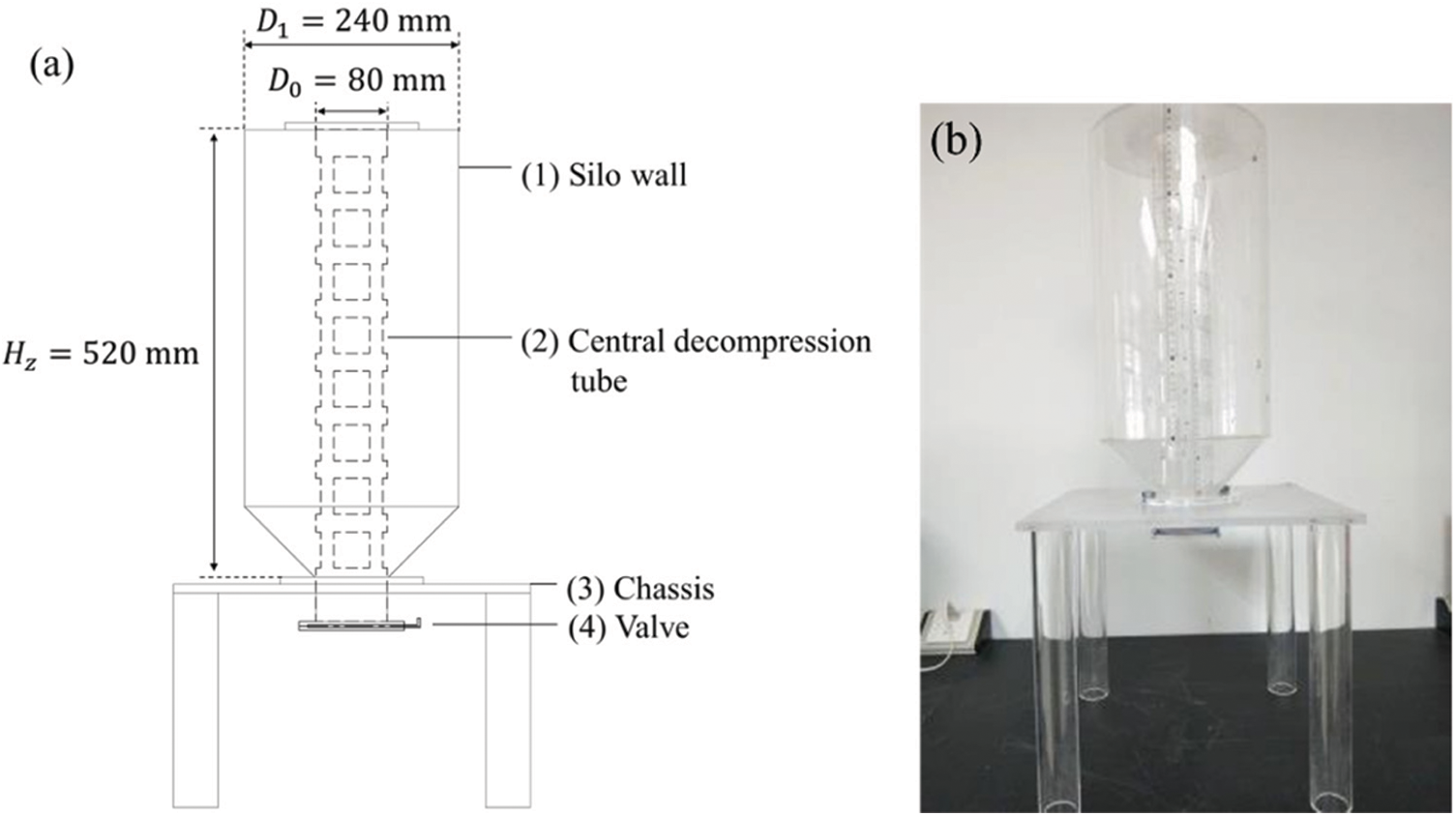
Figure 1: Experimental device of granular flow: (a) schematic diagram of the experiments; (b) the experimental apparatus
According to the DEM model, some physical parameters of grains, such as the rolling friction coefficient, static friction coefficient, elasticity modulus, Poisson’s ratio, and restitution coefficient, etc. directly affect the reliability of simulation results. Meanwhile, it has been proved that the material properties of grains played a great role in the wall pressure and flow patterns during the discharging process [7]. In addition, a single spherical grain cannot reflect the real properties of soybean grains. Therefore, the combination of four spherical elements is used to construct the soybean grain which is 6.8 mm
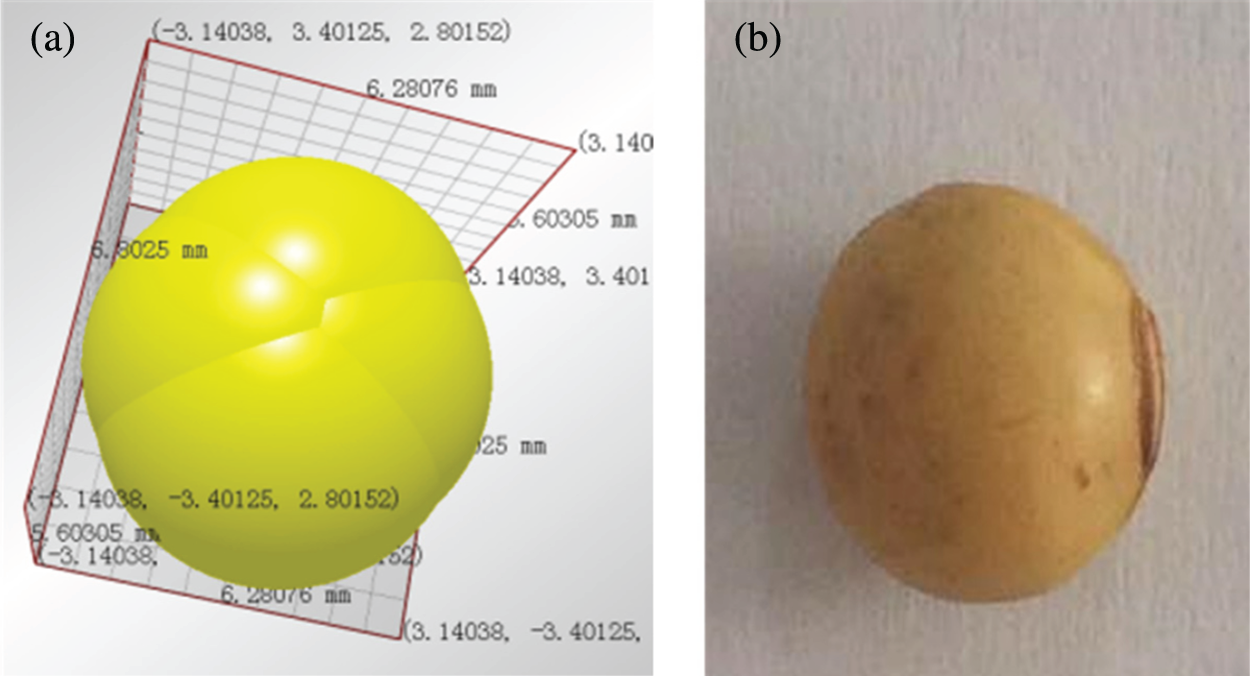
Figure 2: Grain model: (a) DEM model; (b) the real soybean
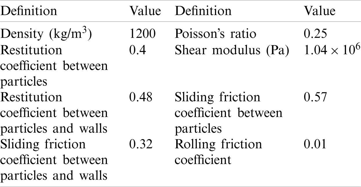
Table 1: DEM simulation parameters for granular flow
3.3 Experimental Validation of Hopper Discharge
The filling and discharging experiments are separately carried out. One is performed in a silo without a central decompression tube, and the other is performed in a silo with a central decompression tube. The filling method has a great influence on the flow state of grains [37]. Therefore, the filling mode of soybeans is the same as that in the actual engineering application, namely tubular filling.
After the silo without a central decompression tube is filled with grains through the central orifice, the soybeans form an angle of repose on the top of the silo. When the valve is opened, the height of granular materials in the silo will gradually decreases, and the angle of repose at the top of the silo will not be damaged in the early stage. As the height of the granular systems decreases, the angle of repose will gradually disappear. Moreover, the experimental results of the discharging process of grains are shown in Fig. 3, and the corresponding simulation results are shown in Fig. 4.
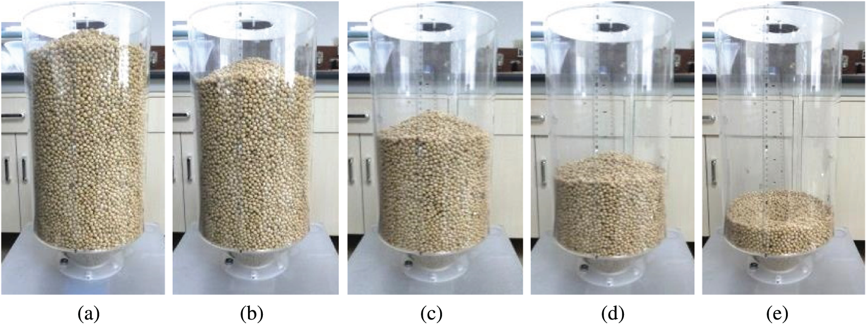
Figure 3: Experimental results of the discharging process in the silo without a central decompression tube (a)
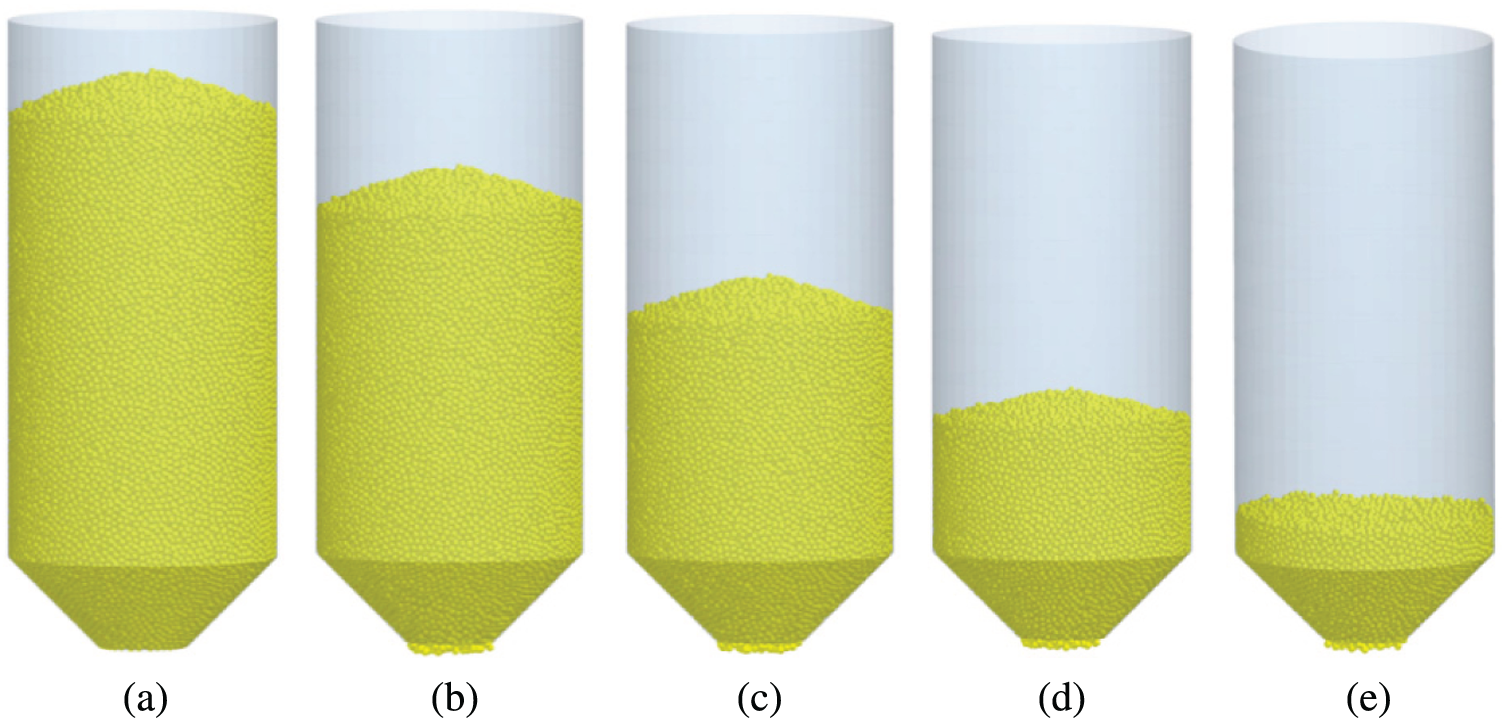
Figure 4: DEM simulations of the discharging process in the silo without a central decompression tube. (a)
The silo with a central decompression tube is filled through the central orifice. The grains flow out from the square hole of the central decompression tube and form a natural accumulation state. After the silo is filled with grains, an angle of repose is formed on the surface of the granular bed, as shown in Fig. 5. When the valve is opened, the grains in the central decompression tube flow out. Finally, the angle of repose of granular materials at the top of the silo disappears, and soybeans gradually flow out in the form of funnel flow, as shown in Fig. 6.
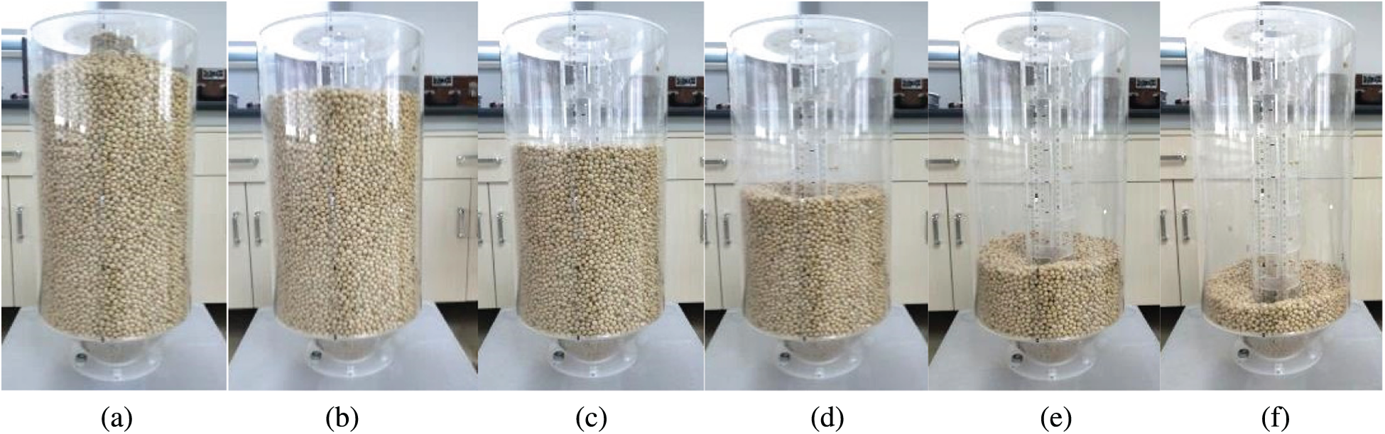
Figure 5: Experimental results of the discharging process of grains in a silo with a central decompression tube (a)
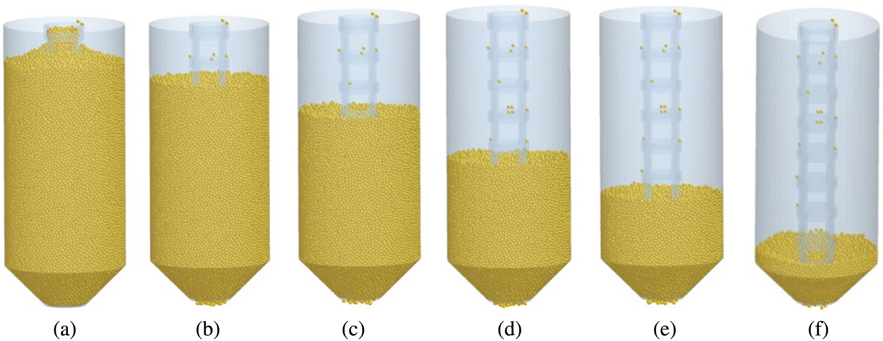
Figure 6: DEM results of the discharging process of grains in a silo with a central decompression tube. (a)
By comparing Figs. 5 and 6, the macroscopic flow phenomena of grains in the experiment and simulation are almost the same. In order to further compare the consistency of the experiment and simulation, the outflow mass of soybeans is measured by controlling the valve during the discharging process. In the DEM simulations, the outflow mass of soybeans is measured and compared with the experimental results. Fig. 7 shows a comparison of the outflow mass of particles in a silo without a central decompression tube between the experimental and simulation results. Fig. 8 shows a comparison of the outflow mass of particles in a silo with a central decompression tube between the experimental and simulation results. Results show that experimental results are basically consistent with the simulation results. Meanwhile, it is shown that the DEM simulation parameters are suitable for simulating the flow process of grains.
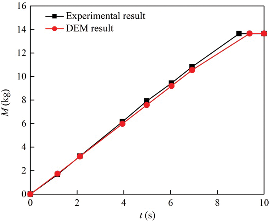
Figure 7: The experimental and simulated results of the outflow mass of particles in the silo without a central decompression tube
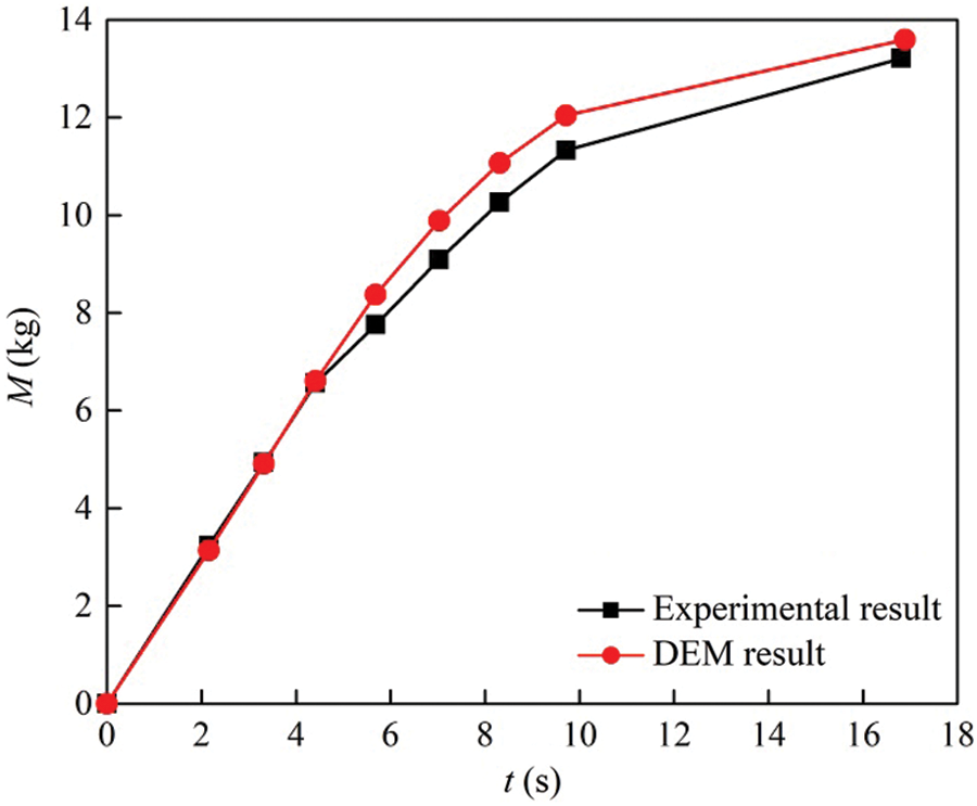
Figure 8: The experimental and simulated results of the outflow mass of particles in the silo with a central decompression tube
In DEM simulations, particles are colored by layers. It can be observed that the grains move downward as a whole in the silo without a central decompression tube. This flow state is the mass flow. When the height of grains is lower than 390 mm, the flow pattern transition occurs and the particles are in the funnel flow, as shown in Fig. 9. In order to observe the flow state of particles, the particles are layered and colored in Figs. 9 and 11. Fig. 10 shows the velocity distribution of grains in the silo, and the red area indicates the maximum particle velocity. In the discharging process, the particle velocity in the green area is relatively low, while the grains in the blue areas have almost the same velocity.
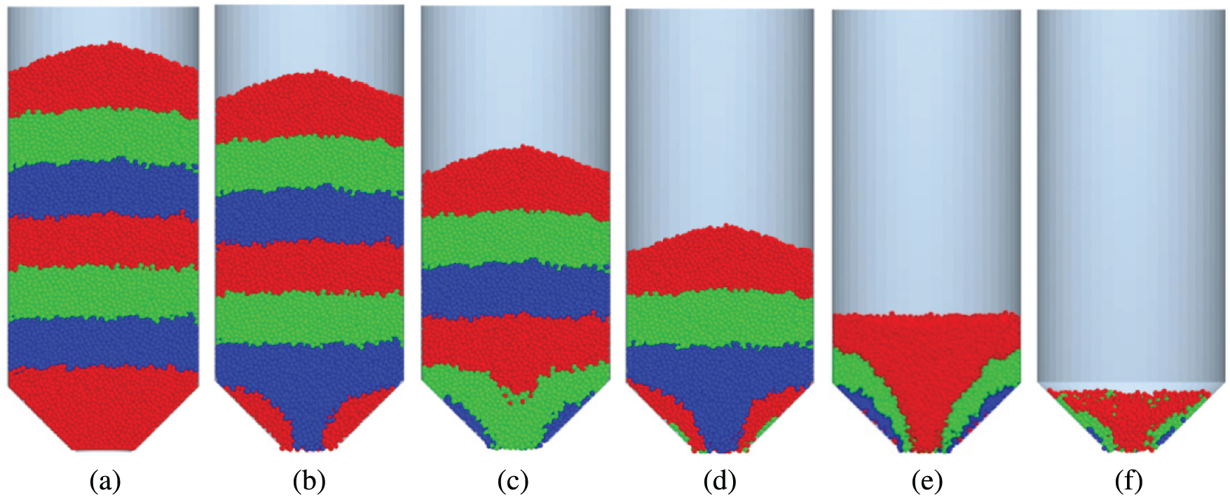
Figure 9: Snapshots of the flow pattern in the silo without a central decompression tube. (a)
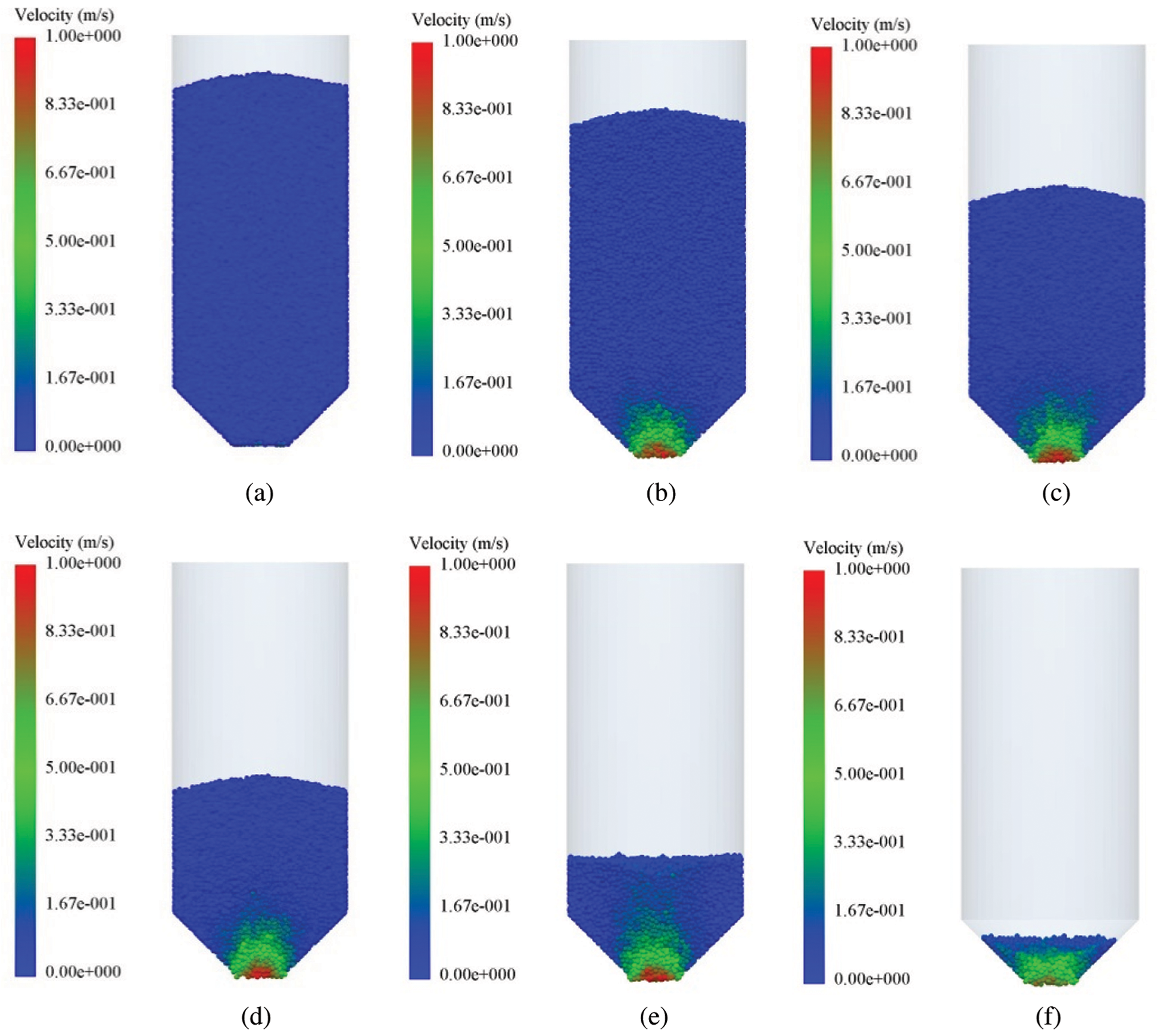
Figure 10: Velocity distribution of grains in the silo without a central decompression tube. (a)
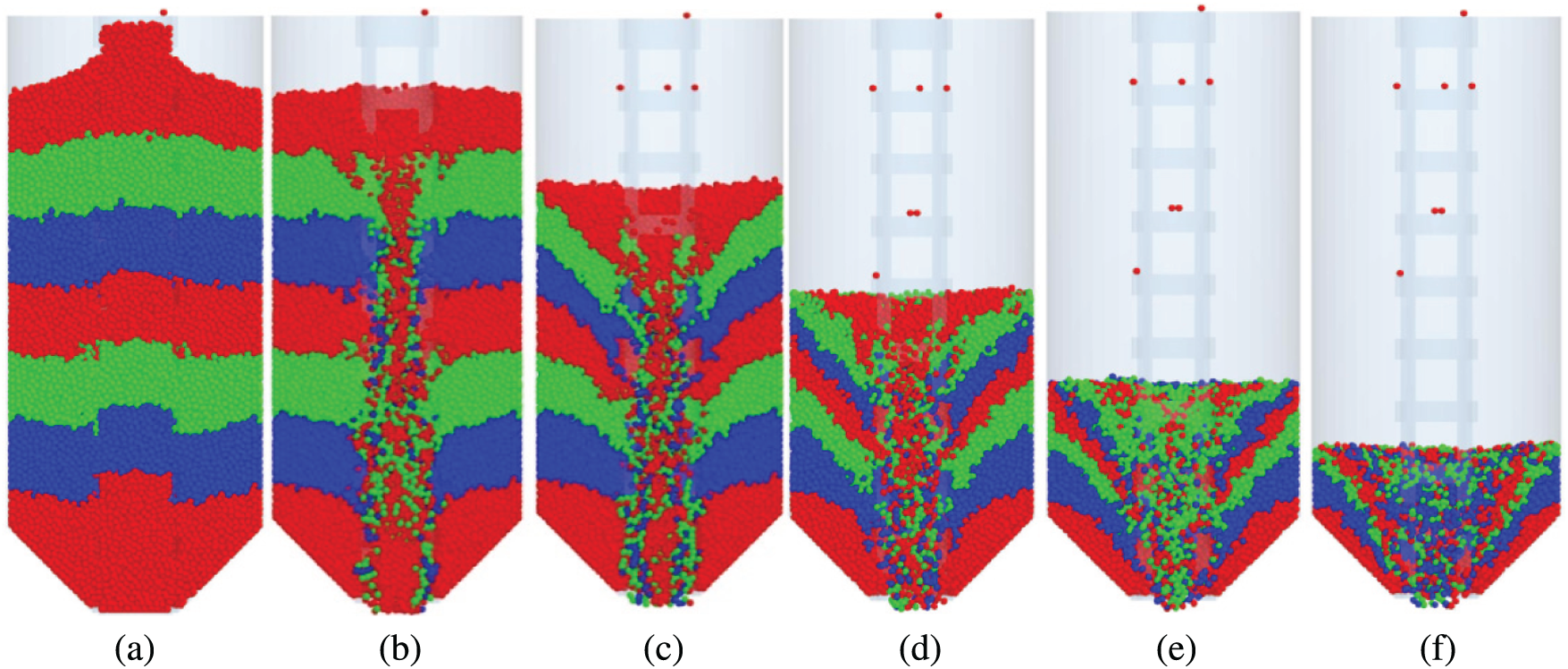
Figure 11: Snapshots of the flow pattern in the silo with a central decompression tube. (a)
During the discharging process of granular materials, the central decompression tube plays a role in diverting the flow patterns. When the outlet is opened, the grains in the tube flow out in the form of funnel flow, as shown in Fig. 11. Since the squeezing force between particles is smaller than that between particles outside the tube and the squeezing force of particles on the surface of the granular bed is smaller than that of the internal bed, the grains on the surface of the granular bed flow into the decompression tube through the hole and flow out of the silo. In addition, the grains in the middle and lower layers cannot flow into the tube due to greater extrusion force, and the grains move downward in an orderly way. Therefore, the grains have the same vertical velocity, which reduces the dynamic pressure during the discharging process. Moreover, the grains in the tube have a relatively higher flow rate when the outlet is opened, and the grains in the upper part of the silo near the decompression tube have a relative velocity. The grains in the lower part of the silo have a greater extrusion force, and the grains outside the tube have no relative velocity, as shown in Fig. 12.
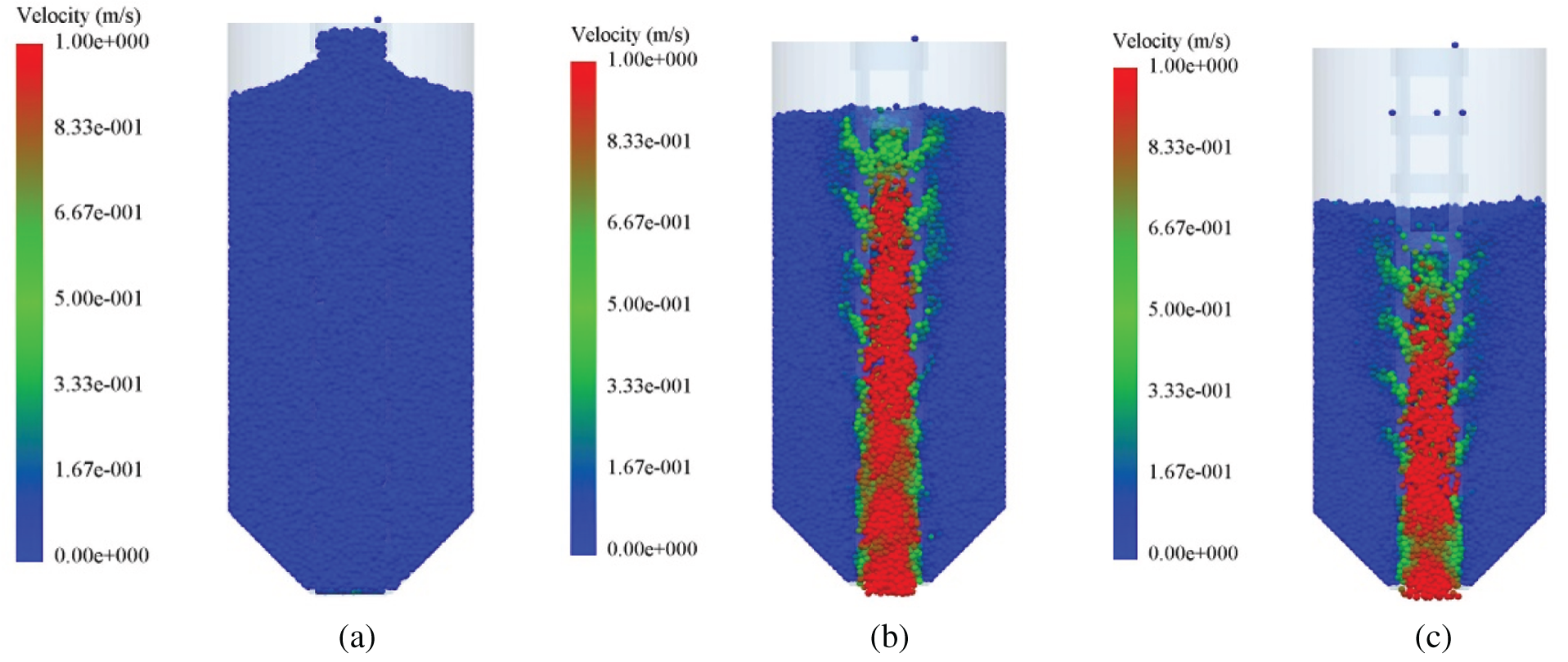
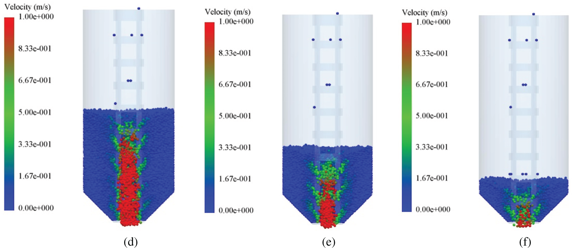
Figure 12: Velocity distribution of grains in the silo with a central decompression tube. (a)
Mass flow index (MFI) can be used to evaluate the flow pattern of grains [38,39], expressed as
where Vw and Vc are the particle velocity in the center and near the wall, respectively. When MFI > 0.3, the flow state is the mass flow; whereas MFI < 0.3, it is the funnel flow. Therefore, the central slice of the silo with a thickness of 25 mm is selected and 14 cubes near the wall are shown in Fig. 13. Meanwhile, the particle velocity in each black cell is averaged at each time step.
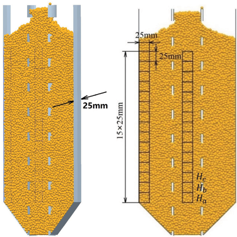
Figure 13: Central slice of a silo
The MFI in the silo without a central decompression tube is greater than 0.3 within the range of 2 to 5 s, and the particles in the silo are the mass flow. When
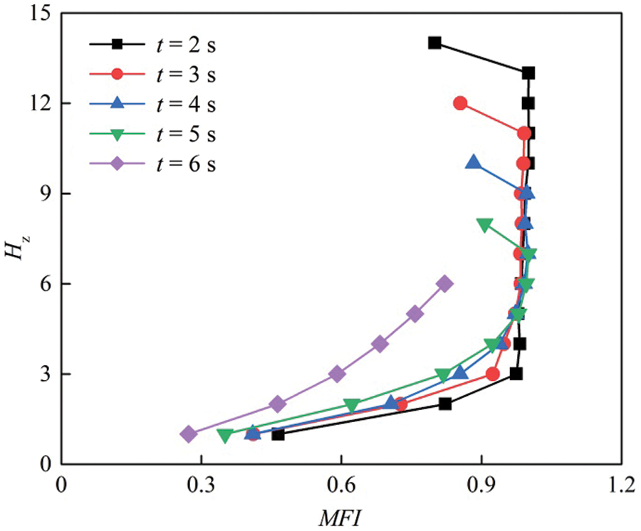
Figure 14: MFI in the silo without a central decompression tube
Figure 15: MFI in the silo without a central decompression tube
Figure 16: MFI in the silo with a central decompression tube
4.2 Distribution of Wall Pressure
To compare the sidewall pressures of the two silos in the static state and the dynamic discharging process, six regions are counted along the Y-axis of the silos in DEM simulations, as shown in Fig. 17.
Figure 17: Statistical diagram of pressure distribution in the silo
The two silos are filled with the same mass of grains. Fig. 18 shows the wall pressure in the silo without a central decompression tube versus time. The wall pressure is denoted as Pn. It is shown that the static area (H2) has the maximal pressure, and the maximal dynamic pressure also occurs on this layer during the discharging process. The corresponding overpressure coefficient is about 1.18. The overpressure coefficient is expressed as
where Pnd is the maximal dynamic pressure of the wall. Pns is the maximal static pressure of the wall. The overpressure means the pressure is higher than the maximal static pressure, and this phenomenon is not observed on the upper layers. It is because the pressure on this layer is relieved at the initial moment of discharging and decreases sharply. Meanwhile, the grains located in the upper layer have a smaller extrusion force and flow downward as a whole. As a result, the sidewall pressure gradually decreases.
Figure 18: Wall pressure in the silo without a central decompression tube during the discharging process
Fig. 19 shows the wall pressure in the silo with a central decompression tube versus time. It is shown that the static area (H2) has the maximal pressure, and the maximal dynamic pressure occurs on this layer during the discharging process. The corresponding overpressure coefficient is about 1.32. On the upper layers, the overpressure is not observed. It is because the pressure on this layer is relieved at the initial moment of discharging process. The particles are in the mass flow, and the particles located on the uppermost layer flow into the tube.
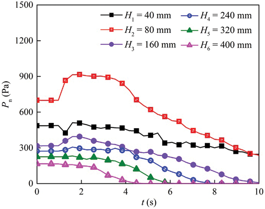
Figure 19: Wall pressure in the silo with a central decompression tube during the discharging process
By comparing the wall pressures of two silos at different heights, the maximal wall pressure and the overpressure are observed when
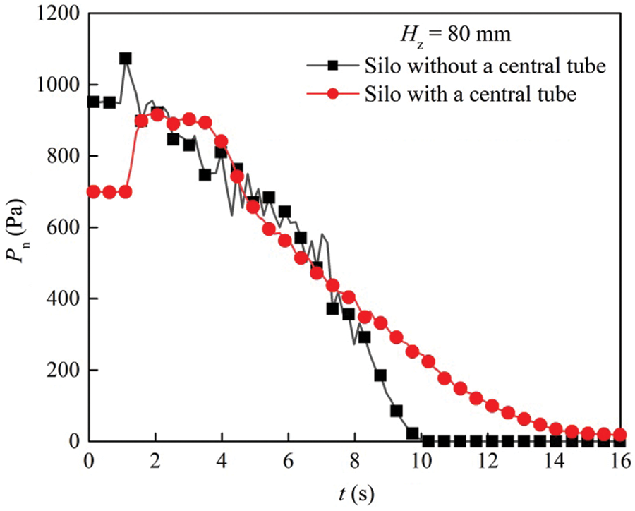
Figure 20: Wall pressure of the silos with and without a central decompression tube as a function of time when Hz = 80 mm
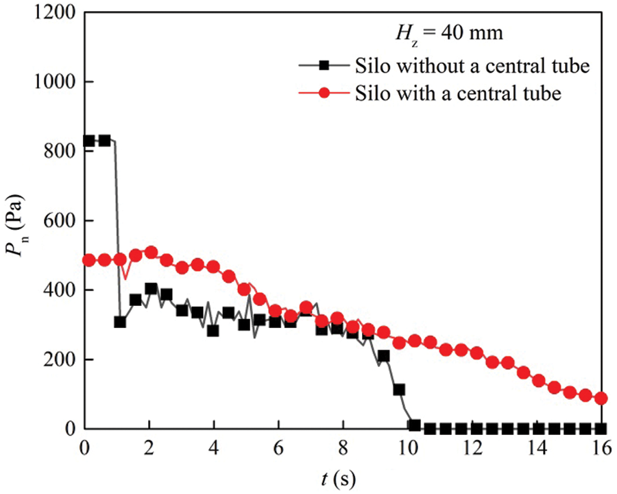
Figure 21: Wall pressure of the silos with and without a central decompression tube as a function of time when Hz = 40 mm
A similar phenomenon is observed in Fig. 22. During the discharging process, overpressure exists in both silos. The static pressure and overpressure on the sidewall of the silo without a central decompression tube are higher than those of the silo with a central decompression tube. When Hz = 360 mm, overpressure always exists in the silo without a central decompression tube. However, there is no overpressure in the silo with a central decompression tube, as shown in Fig. 23. This is because the grains in the former are in mass flow, while the grains in the latter are in funnel flow. In addition, the wall pressure gradually decreases when more grains flow into the central hole. At the top of the granular bed, the wall pressure of two silos decreases as the height of granular materials decreases.
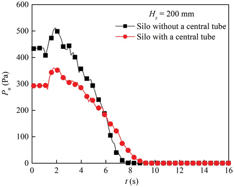
Figure 22: Wall pressure of the silos with and without a central decompression tube as a function of time when Hz = 200 mm
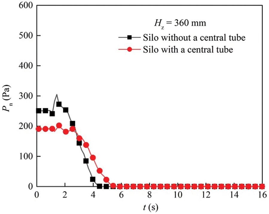
Figure 23: Wall pressure of the silos with and without a central decompression tube as a function of time when Hz = 360 mm
Except for the bottom layer, the wall pressure of the silo with a central decompression tube is lower than that of the silo without a central decompression tube during the discharging process, as shown in Fig. 24. The flow rate of grains in the silo with a central decompression tube is lower than in the silo without a central decompression tube, and the frequency of pressure oscillation on the sidewall of the silo with a central decompression tube is lower than that of the silo without a central decompression tube during the discharging process. Therefore, the silo with a central decompression tube is more conducive to grain storage and discharging than the silo without a central decompression tube.
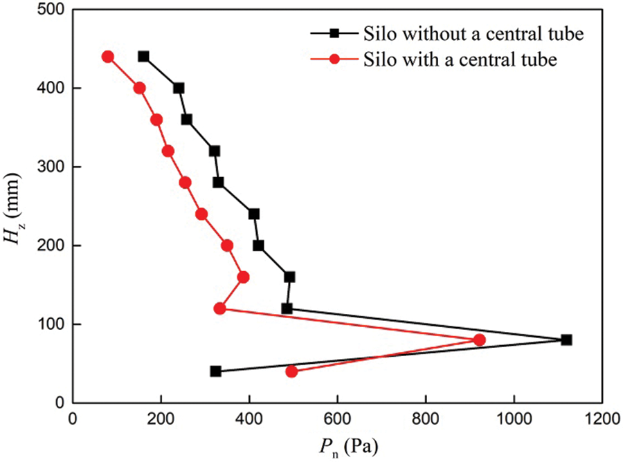
Figure 24: Relationship between heights of granular beds and wall pressure for different silos
The flow characteristics of grains in a silo with a central decompression tube were studied through experimental measurements and discrete element methods in this study. The DEM results were compared with the experimental results, which verified the applicability of the DEM model for the hopper discharge of granular materials. Then, the influences of the central decompression tube on the flow pattern and wall pressure were analyzed. Results showed that the particles in the silo without a central decompression tube were in mass flow, while the particles in the silo with a central decompression tube were in funnel flow. Therefore, the central decompression tube caused the flow pattern transition of granular materials. Moreover, the maximal wall pressure of the silo with a central decompression tube was in the upper part of the hopper, and the overpressure reached 82% of the height of the silo during the discharging process. Although this overpressure coefficient was larger than that of the silo without a central decompression tube, the maximal pressure was always lower than the static and dynamic pressures of the silo without a central decompression tube. Overall, the central decompression tube in the silo effectively improved the safety of the silos.
Funding Statement: We would like to acknowledge the finical support by the Key Laboratory of Agro-Products Postharvest Handling, Ministry of Agriculture support (Grant No. KLAPPH2-2017-04).
Conflicts of Interest: The authors declare that there is no conflict of interest regarding the publication of this paper.
1. Zuriguel, I., Garcimartin, A., Maza, D. (2005). Jamming during the discharge of granular matter from a silo. Physical Review E, 71(5), 51303. DOI 10.1103/PhysRevE.71.051303. [Google Scholar] [CrossRef]
2. Brauer, K., Pfitzner, M., Krimer, D. O. (2006). Granular elasticity: Stress distributions in silos and under point loads. Physical Review E, 74(6), 61311. DOI 10.1103/PhysRevE.74.061311. [Google Scholar] [CrossRef]
3. Kiwing, T., Lai, P. Y., Pak, H. K. (2001). Jamming of granular flow in a two-dimensional hopper. Physical Review Letter, 86(1), 71–74. DOI 10.1103/PhysRevLett.86.71. [Google Scholar] [CrossRef]
4. Hirshfeld, D., Rapaport, D. C. (2001). Granular flow from a silo: Discrete-particle simulations in three dimensions. European Physical Journal E Soft Matter, 4(2), 93–199. DOI 10.1007/s101890170128. [Google Scholar] [CrossRef]
5. Muite, B. K., Quinn, S. F., Sundaresan, S., Rao, K. K. (2004). Silo music and silo quake: Granular flow-induced vibration. Powder Technology, 145(3), 190–202. DOI 10.1016/j.powtec.2004.07.003. [Google Scholar] [CrossRef]
6. Tejchman, J. (1998). Silo-quake-measurements a numerical approach and a way for its suppression. Thin-Walled Structures, 31(1–3), 137–158. DOI 10.1016/S0263-8231(98)00012-3. [Google Scholar] [CrossRef]
7. Wang, P., Zhu, L., Zhu, X. (2016). Flow pattern and normal pressure distribution in flat bottom silo discharged using wall outlet. Powder Technology, 295(35), 104–114. DOI 10.1016/j.powtec.2016.03.036. [Google Scholar] [CrossRef]
8. Jenike, A. W. (1987). A theory of flow of particulate solids in converging and diverging channels based on a conical yield function. Powder Technology, 50(3), 229–236. DOI 10.1016/0032-5910(87)80068-2. [Google Scholar] [CrossRef]
9. Karlsson, T., Klisinski, M., Runesson, K. (1998). Finite element simulation of granular material flow in plane silos with complication geometry. Powder Technology, 99(1), 29–39. DOI 10.1016/S0032-5910(98)00087-4. [Google Scholar] [CrossRef]
10. Mccabe, R. P. (1974). Flow pattern in granular materials in circular silos. Geotechniqus, 1(1), 45–62. DOI 10.1680/geot.1974.24.1.45. [Google Scholar] [CrossRef]
11. Kotchanova, I. J. (1970). Experiments and theoretical investigations on the discharge of granular material from bins. Powder Technology, 4(1), 32–37. DOI 10.1016/0032-5910(70)80005-5. [Google Scholar] [CrossRef]
12. Zhu, H. P., Yu, A. B. (2005). Micromechanic modeling and analysis of unsteady-state granular flow in a cylindrical hopper. Journal of Engineering Mathematics, 52(1), 307–320. DOI 10.1007/s10665-004-6011-8. [Google Scholar] [CrossRef]
13. Zhu, H. P., Yu, A. B. (2004). Steady-state granular flow in a threedimensional cylindrical hopper with flat bottom: Microscopic analysis. Journal of Physics D: Applied Physics, 37(10), 1497–1508. DOI 10.1088/0022-3727/37/10/013. [Google Scholar] [CrossRef]
14. Qadir, A., Guo, H., Liang, X., Shi, Q., Sun, G. (2010). Effect of the ratios of diameter of silo to bead on the pressure screening in granular columns. European Physical Journal E, 31(3), 311–314. DOI 10.1140/epje/i2010-10581-7. [Google Scholar] [CrossRef]
15. Cundall, P. A. A. (1971). Computer model for simulating progressive large-scale movements in blocky rock systems. Proceeding of the Symposium International Society Rock Mechanics, 1(2), 132–150. [Google Scholar]
16. Cundall, P. A., Strack, O. D. L. (1979). A discrete numerical model for granular assemblies. Geotechique, 29(1), 47–65. DOI 10.1680/geot.1979.29.1.47. [Google Scholar] [CrossRef]
17. Oldal, I., Safranyik, F. (2015). Extension of silo discharge model based on discrete element method. Journal of Mechanical Science and Technology, 29(9), 3789–3796. DOI 10.1007/s12206-015-0825-3. [Google Scholar] [CrossRef]
18. Weinhart, T., Labra, C., Luding, S., Ooi, J. Y. (2016). Influence of coarse-graining parameters on the analysis of DEM simulations of silo flow. Powder Technology, 293(2), 138–148. DOI 10.1016/j.powtec.2015.11.052. [Google Scholar] [CrossRef]
19. Wang, J., Yu, H. S., Langston, P., Fraige, F. (2011). Particle shape effects in discrete element modelling of cohesive angular particles. Granular Matter, 13(1), 1–12. DOI 10.1007/s10035-010-0217-4. [Google Scholar] [CrossRef]
20. González-Montellano, C., Ramírez, Á., Gallego, E., Ayuga, F. (2011). Validation and experimental calibration of 3D discrete element models for the simulation of the discharge flow in silos. Chemical Engineering Science, 66(21), 5116–5126. DOI 10.1016/j.ces.2011.07.009. [Google Scholar] [CrossRef]
21. Zhu, H. P., Wu, Y. H., Yu, A. B. (2005). Discrete and continuum modelling of granular flow. Particuology, 6(6), 354–363. DOI 10.1016/S1672-2515(07)60215-2. [Google Scholar] [CrossRef]
22. Leszczynski, J. S., Blaszczyk, T. (2011). Modeling the transition between stable and unstable operation while emptying a silo. Granular Matter, 13(4), 429–438. DOI 10.1007/s10035-010-0240-5. [Google Scholar] [CrossRef]
23. Mathews, J. C., Wu, W. (2016). Model tests of silo discharge in a geotechnical centrifuge. Powder Technology, 293(1), 3–14. DOI 10.1016/j.powtec.2015.11.025. [Google Scholar] [CrossRef]
24. Zhang, Y., Jia, F., Zeng, Y., Han, Y., Xiao, Y. (2018). DEM study in the critical height of flow mechanism transition in a conical silo. Powder Technology, 331(1), 98–106. DOI 10.1016/j.powtec.2018.03.024. [Google Scholar] [CrossRef]
25. Janssen, H. A. (1985). Versuche über Getreidedruck in Silozellen. Zeitschrift Verein Deutscher Ingenieure, 39, 1045–1049. [Google Scholar]
26. Brown, C. J., Lahlouh, E. H., Rotter, J. M. (2000). Experiments on a square plan form steel silo. Chemical Engineering Science, 55(20), 4399–4413. DOI 10.1016/S0009-2509(99)00574-6. [Google Scholar] [CrossRef]
27. Rombach, G., Eibl, J. (1995). Granular flow of materials in silos: Numerical results. Bulk Solid Handing, 1, 65–70. [Google Scholar]
28. Takhtamishev, S. G. (1963). 1947 Report by Turitzin, A M. Journal of the Structural Division, 89, 49–73. [Google Scholar]
29. Langston, P. A., Tuzun, U. (1995). Continuous potential discrete particle simulation of stress and velocity fields in hopper. transition from fluid to granular flow. Chemical Engineering, 50(9), 967–987. DOI 10.1016/0009-2509(94)00467-6. [Google Scholar] [CrossRef]
30. Haertl, J., Ooi, J. Y., Rotter, J. M., Wójcik, M., Ding, S. X. et al. (2007). The influence of a cone-in-cone insert on flow pattern and wall pressure in a full-scale silo. Chemical Engineering Research and Design, 86(4), 370–378. DOI 10.1016/j.cherd.2007.07.001. [Google Scholar] [CrossRef]
31. Yang, S., Hsiau, S. (2001). The simulation and experimental study of granular materials discharged from a silo with the placement of inserts. Powder Technology, 120(3), 244–255. DOI 10.1016/S0032-5910(01)00277-7. [Google Scholar] [CrossRef]
32. Hidalgo, R. C., Lozano, C., Zuriguel, I., Garcimartín, A. (2013). Force analysis of clogging arches in a silo. Granular Matter, 15(6), 841–848. DOI 10.1007/s10035-013-0451-7. [Google Scholar] [CrossRef]
33. Ji, S., Wang, S., Peng, Z. (2019). Influence of external pressure on granular flow in a cylindrical silo based on discrete element method. Powder Technology, 356, 702–714. DOI 10.1016/j.powtec.2019.08.083. [Google Scholar] [CrossRef]
34. Ramírez, A., Jørgen, N., Ayuga, F. (2010). Pressure measurements in steel silos with eccentric hoppers. Powder Technology, 201(1), 7–20. DOI 10.1016/j.powtec.2010.02.027. [Google Scholar] [CrossRef]
35. Zhong, Z., Ooi, J. Y., Rotter, J. M. (2001). The sensitivity silo flow and wall stresses to filling method. Engineering Structures, 23(7), 756–767. DOI 10.1016/S0141-0296(00)00099-7. [Google Scholar] [CrossRef]
36. Grima, A. P., Peter, W. W. (2011). Development and validation of calibration methods for discrete element modeling. Granular Matter, 13(2), 127–132. DOI 10.1007/s10035-010-0197-4. [Google Scholar] [CrossRef]
37. Masson, S., Martinez, J. (2000). Effect of particle mechanical properties on silo flow and stresses from distinct element simulations. Powder Technology, 109(1–3), 164–178. DOI 10.1016/S0032-5910(99)00234-X. [Google Scholar] [CrossRef]
38. Johanson, J. R. (1962). Stress and velocity fields in gravity flow of bulk solids. Journal of Applied Mechanics, 31(3), 499–506. DOI 10.1115/1.3629668. [Google Scholar] [CrossRef]
39. González-Montellano, C., Ayuga, F., Ooi, J. Y. (2011). Discrete element modelling of grain flow in a planar silo: Influence of simulation parameters. Granular Matter, 13(2), 149–158. DOI 10.1007/s10035-010-0204-9. [Google Scholar] [CrossRef]
 | This work is licensed under a Creative Commons Attribution 4.0 International License, which permits unrestricted use, distribution, and reproduction in any medium, provided the original work is properly cited. |