| Computer Modeling in Engineering & Sciences |
DOI: 10.32604/cmes.2021.016181
ARTICLE
Construction of Design Guidelines for Optimal Automotive Frame Shape Based on Statistical Approach and Mechanical Analysis
1Mazda Motor Corporation, 3-1 Shinchi, Fuchu-cho, Aki-gun, Hiroshima, 730-8670, Japan
2Department of Applied Mechanics and Aerospace Engineering, School of Fundamental Science and Engineering, Waseda University, 3-4-1 Okubo, Shinjuku-ku, Tokyo, 169-8555, Japan
3Division of Advanced Science and Engineering, Graduate School of Advanced Science and Engineering, Hiroshima University, 1-4-1 Kagamiyama, Higashihiroshima, Hiroshima, 739-8527, Japan
*Corresponding Author: Akihiro Takezawa. Email: atakezawa@waseda.jp
Received: 15 February 2021; Accepted: 09 May 2021
Abstract: A body frame composed of thin sheet metal is a crucial structure that determines the safety performance of a vehicle. Designing a correct weight and high-performance automotive body is an emerging engineering problem. To improve the performance of the automotive frame, we attempt to reconstruct its design criteria based on statistical and mechanical approaches. At first, a fundamental study on the frame strength is conducted and a cross-sectional shape optimization problem is developed for designing the cross-sectional shape of an automobile frame having a very high mass efficiency for strength. Shape optimization is carried out using the nonlinear finite element method and a meta-modeling-based genetic algorithm. Data analysis of the obtained set of optimal results is performed to identify the dominant design variables by employing the smoothing spline analysis of variance, the principal component analysis, and the self-organizing map technique. The relationship between the cross-sectional shape and the objective function is also analyzed by hierarchical clustering. A design guideline is obtained from these statistical approach results. A comparison between the statistically obtained design guideline and the conventional one based on the designers’ experience is performed based on mechanical interpretation of the optimal cross-sectional frame. Finally, a mechanically reasonable new general-purpose design guideline is proposed for the cross-sectional shape of the automotive frame.
Keywords: Automotive structure; shape optimization; data mining; statistical approach; crash-performance
A body frame formed of thin sheet metal is a crucial structure that determines the critical performance of an automobile, such as the supporting mechanical components and the body itself having stiffness against loads from inside and outside and protecting the passengers. As the passenger safety criteria are becoming increasingly stricter, the bodies of new automobiles tend to be heavy to achieve the appropriate rigidity without any sophisticated design technique. However, a heavy body weight is a major factor that determines the fuel effectiveness of a vehicle and this is another important criterion for automobiles. Furthermore, low environmental load products, i.e., the products that produce a low amount of CO2, are in high demand. Thus, designing an automotive body that has the appropriate weight as well as high-performance is one of the emerging engineering problems.
For improving the body frame design of an automobile, several cross-sectional shape optimization methods, employing numerical optimization algorithms, have been proposed [1–8]. However, although new complicated shapes, which improve the objective function, were obtained in these studies, the mechanical aspect of the design that is useful for the engineering design could not be interpreted. Without this information, a general guideline for improving the overall design performance is difficult to construct.
A few studies focused on understanding the mechanical aspect of the optimal structure by using simple discrete elements such as a plate and beam elements [9–11]. However, since these studies are limited to linear elastic analysis, they are unsuitable for optimizing the nonlinear performance of the automotive body frame, such as its crashworthiness.
On the other hand, in recent years, research on applying data-mining-based strategies for improving the efficiency of the heuristic optimization algorithms has become popular [12–15]. However, most of these studies focus on the optimization efficiency without analyzing the mechanical aspect of the optimal solution. A design process that can derive a general-purpose design guideline for improving the objective function is required based on the mathematical analysis and the engineering interpretation for big data obtained by optimization.
Taking the above mentioned points into consideration, in this work, we have constructed a process for extracting new design principles from various design candidates obtained by optimization. This research work has been conducted in the following steps follows: (i) A fundamental study on the frame strength has been conducted and a cross-sectional shape optimization problem has then been constructed for designing a cross-sectional frame shape of an automobile having a very high mass efficiency for strength. (ii) Shape optimization has been done by using the nonlinear finite element method (FEM) and a meta-modeling-based genetic algorithm (GA). (iii) Data analysis of the obtained set of optimal results has been performed for identifying the crucial design variables on the basis of the smoothing spline analysis of variance (SS-ANOVA), the principal component analysis (PCA), and the self-organizing map (SOM) technique. In addition, hierarchical clustering has been employed for analyzing the relationship between the cross-sectional shape and the objective function. (iv) A mechanical interpretation of the optimal cross-sectional frame has been done from the engineering point of view and a general-purpose design guideline has been proposed.
2 Dataset of Automobile Frame Optimization
A schematic indicating the optimization parameters used for the cross-sectional frame shape of the car body is shown in Fig. 1. The objective function is the bending strength and mass of the frame, which are essential for the collision safety performance of the automobile. The bending strength is calculated by the transient non-linear finite element analysis of the three-point bending as shown in Fig. 2 using the commercial software LS-DYNA. The maximum reaction force of the pushrod is regarded as the bending strength. The material is assumed as steel having the piecewise linear plasticity with Young’s modulus 206 GPa, Poisson’s ratio 0.3, yield stress 1450 MPa, and ultimate tensile stress 2350 MPa.

Figure 1: Cross-sectional view of the initial and optimal shapes of the frame. The coordinates of the design variables have been defined as follows: d1 and d2 are the x and y coordinates of Point A, d3 and d4 are the x and y coordinates of Point B, d5 and d6 are the x and y coordinates of Point C, d7 is the x coordinate of Point D, d8 and d9 are the x and y coordinates of Point E, d10 and d11 are the x and y coordinates of Point F, and d12: y of Point G

Figure 2: Evaluation model of the bending stiffness of the frame
The design variables are the in-plane coordinates of the seven points of the cross-sectional frame shape, as shown in Fig. 1. Fig. 3 shows a flowchart of the optimization process based on the radial basis function (RBF) and the genetic algorithm (GA). Since the computational cost of the transient non-linear is high, the RBF based meta-modeling approximation was introduced. In the RBF approximation, the response y is approximated as the following weighted sum of the RBF.
where N is the number of RBF,

Figure 3: Flowchart of the optimization process
Fig. 4 shows the distribution of the 600 solutions evaluated using FEM. A Pareto set of the solutions was clearly observed to be formed. Both the bending strength and the weight were improved in some solutions. However, it was difficult to estimate a design guideline useful for general purposes from this result only. Therefore, the design guidelines are clarified by analyzing the data obtained using the optimization procedure described in the following subsections.

Figure 4: Optimal solution set evaluated using FEM for statistical analysis
3 Analysis of the Effect of the Design Variables
3.1 Extraction of the Predominant Contributing Factors
First, the contributions of the 12 design variables to the frame performance,
where
The contribution ratio of i-th design variable is calculated as
Second, PCA is performed for capturing the tendency of the entire set of the design variables and the optimal solutions [18]. PCA is a dimension reduction method that summarizes the multivariate information correlated with each other into a small number of characteristic values that are mutually exclusive. The input dataset vector is formed as
where Height represents the height of the flame cross section. Each item is normalized to the 0–1 range. PCA was performed based on the eigenvalue analysis of the covariance matrix
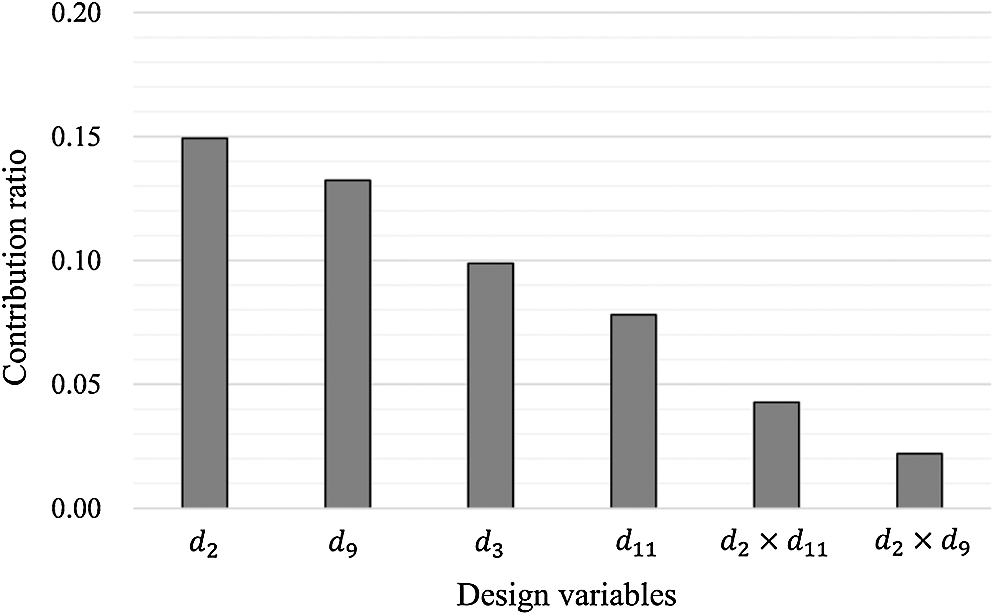
Figure 5: Results of the SS-ANOVA analysis
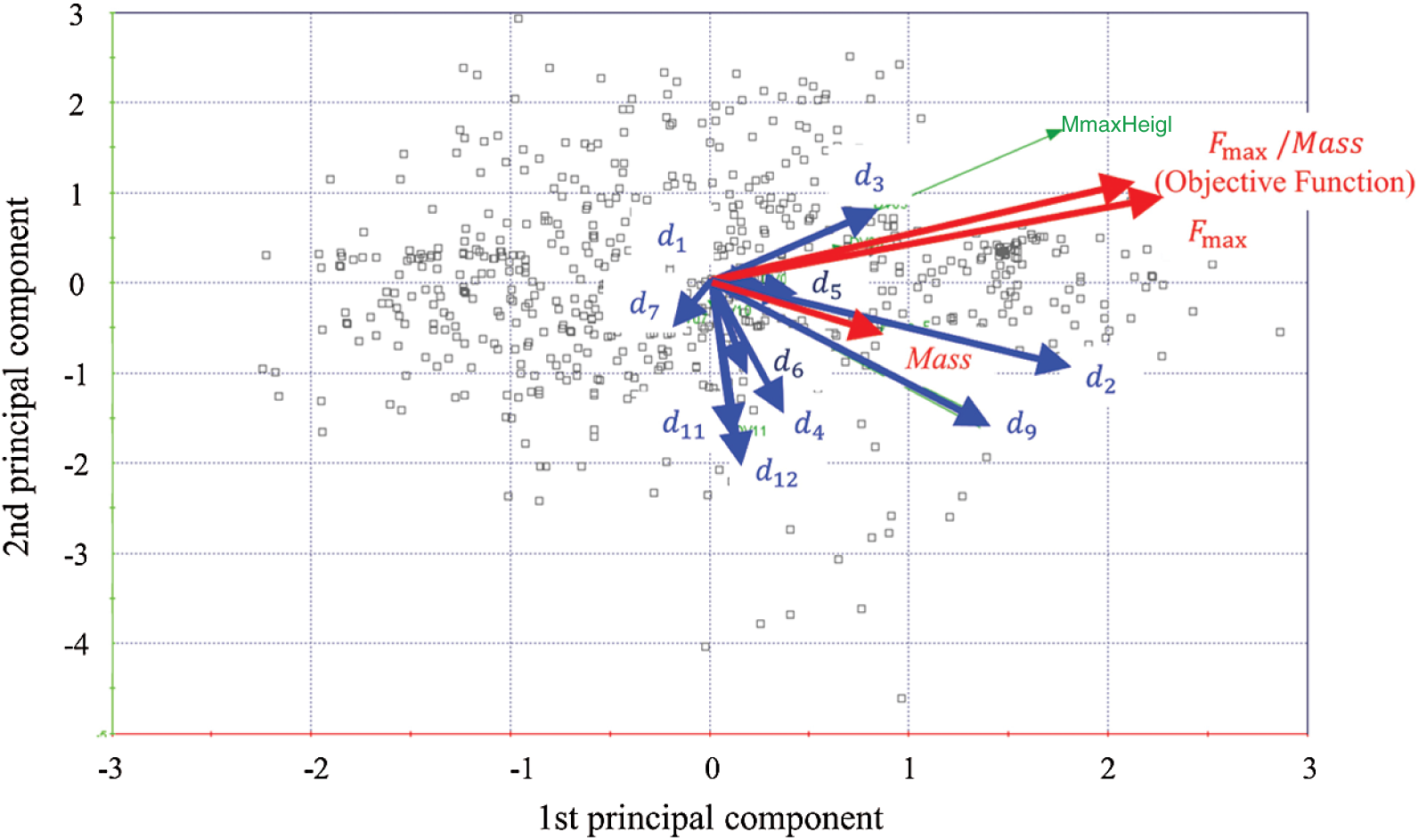
Figure 6: Results of the PCA analysis. The design variables having a direction arrow similar to that of the objective function are regarded to have a substantial effect on the objective function
Finally, an SOM [19] is formed using the vector expressed by (4) on the basis of the value of the objective function. The SOM is a representation of the similarity of design variables in a map space on two dimensions. Fig. 7 shows a representation of SOM on a hexagonal grid, where the input vector is compared to a reference vector and the coordinates of the input vector are transformed to the coordinates of the node with the closest reference vector to the input vector on the map. In Fig. 7, the distribution of values of the objective function and each design variable components in each vector. The design variables that have similar distributions can exhibit similar effects on the objective function. Here, (d3, d8), (d4, d9), (d5, d7), and (d11, d12) are regarded as pairs of design variables exhibiting a similar tendency. (d3, d8) are design variables corresponding to the x-direction, (d4, d9) are those corresponding to the y-direction, (d5, d7) are those corresponding to the x-direction of the neighbor points, and (d11, d12) are those corresponding to the y-direction of the neighboring points. This is certainly the reason for their similarity. Among them, d2 (y coordinate of Point A), d3 (x coordinate of Point B), and d9 (y coordinate of Point E) exhibit a similar distribution with the objective function. These results agree with those of the PCA shown in Fig. 6.
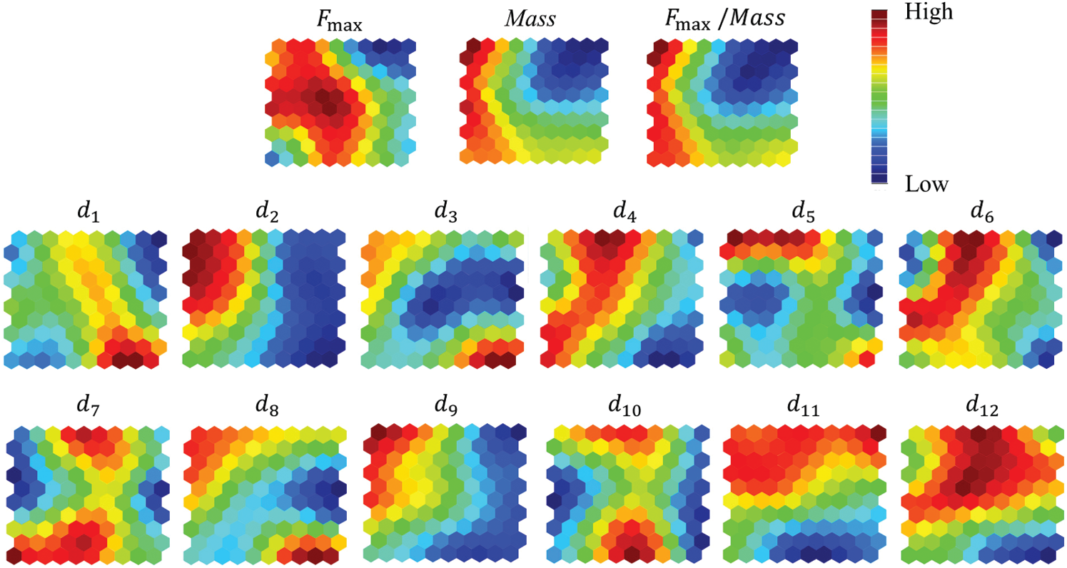
Figure 7: Results of the SOM analysis. Design variables having similar color distribution exhibit similar tendencies for the objective function
3.2 Directional Analysis of the Cross-Section Design
In the previous section, the design variables that are crucial for increasing the objective function were clarified. In this section, a description of the analysis conducts for investigating the relationship between the design variables and the objective function is given and the design guidelines for the cross-sectional shape is considered. As an analytical approach, all data are clustered using two factors, the mass of the frame and the bending strength, and were divided into eight subsets on the basis of these two factors. The cluster analysis identifies homogeneous subgroups of results in a dataset. Based on the distributions of the subgroups, we consider the range of effective values for the design variables required for improving the objective function. The clustering method used in this work is the hierarchical clustering method based on the Ward method which uses the Euclidean distance as an index [20]. The results of clustering are shown in Fig. 8.
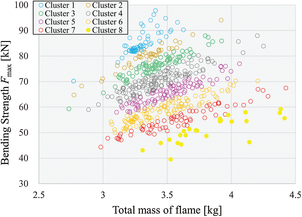
Figure 8: Results of clustering
Next, we analyze the tendency of each design variable by plotting its value range corresponding to high, middle, and low clusters in a parallel coordinates chart. Fig. 9 shows the ranges of the normalized values of the objective function corresponding to each design variable. In Cluster 1, the ranges of the design variables that have a large effect, namely, d2 (y coordinate of Point A), d3 (x coordinate of Point B), and d9 (y coordinate of Point E) are narrow but have large values. In other words, they should be high in order to improve the objective function. The design guideline thus obtained has been visualized as shown on the right side of Fig. 10.
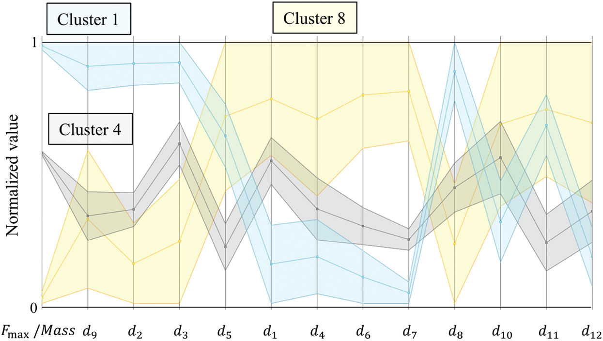
Figure 9: Parallel coordinates chart. The cluster numbers are identical to those in Fig. 8
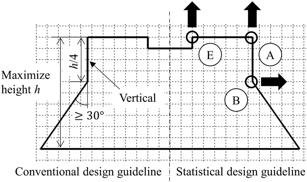
Figure 10: Comparison between the conventional design guideline (left side) and the statistically obtained design guideline (right side)
This section describes the analysis of the design information, obtained from the statistical analysis detailed in the previous section, from an engineering point of view. Generally, the bending strength of the frame is evaluated by the total plastic moment, Mp [21] that is expressed as:
where Zp and
In contrast, in the case of a hollow frame composed of a thin steel plate, such as an automobile frame, the buckling of the thin plate becomes dominant and the buckling deformation occurs before the total plastic moment is reached and this determines the maximum strength. In other words, it is important to suppress the buckling of the thin plates forming the frame. To this end, we have derived the design requirements for suppressing the thin plate buckling by considering the past fundamental engineering studies. This design guideline is shown in Fig. 10 together with the one obtained by the statistical approach. In the conventional design guideline, the shape of the vertical plate in the frame was regarded to influence the buckling effect and the layout vertically and the angle of the inclined plate was also specified.
In the statistically obtained design guideline, the guideline for the position of Points A and E agree with the conventional one. However, the guideline for the position of Point B violates the conventional ones.
In order to analyze the design guideline of the position of Point B, the detailed deformation of the optimal solution was tested. Fig. 11 shows the relationship between the pushrod stroke and the reaction force and also shows the representative deformations of the optimal and the conventional base shapes specified in Fig. 4. It was observed that the inclined wall of the optimal shape became vertical depending on the deformation and contributed to a higher reaction force than the conventional design. Considering this deformation behavior, the preinclined wall layout is quite reasonable. Such a design guideline was first obtained by using a statistical approach.
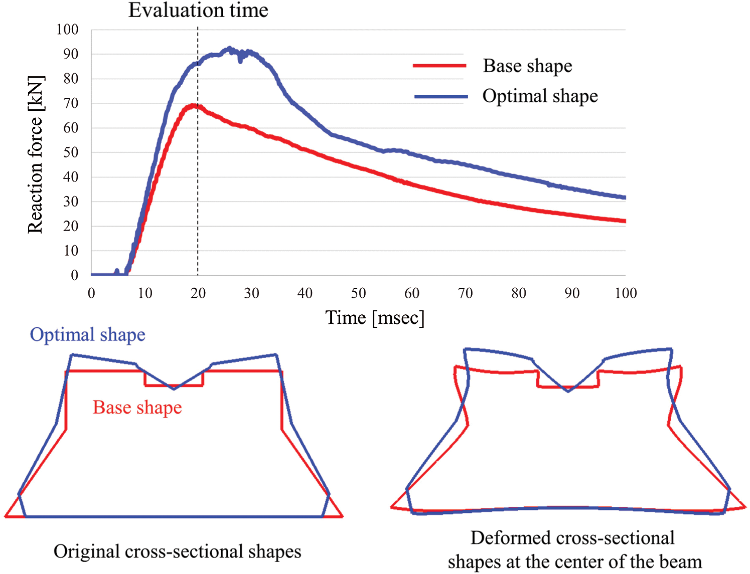
Figure 11: Reaction force histories and the deformation diagrams of the base frame shape and the optimal shape. The deformation diagrams were chosen at the analysis time of 20 ms
By analyzing a large amount of data obtained from the optimization process using the RBF method and the GA using a statistical approach, SS-ANOVA, PCA, SOM, and clustering, we reconstructed the design guideline of an automotive frame. The design target was the cross-sectional shape of an automotive frame and the design objective was to improve the reaction force for the high-speed bar contact on the center with both the side supports. The crucial design factors that have a high contribution to the objective function were chosen and their directions were observed to improve the objective function. The contributions of the 12 design variables to the frame performance were identified using the SS-ANOVA. PCA was performed for capturing the tendency of the entire set of the design variables and the optimal solutions. SOM was formed to identify the similarities of design variables. Clustering was finally performed for investigating the quantitative relationship between the design variables and the objective function.
The two design guidelines were obtained by this process are: (i) the height of the cross-sectional frame should be high to improve the plastic section modulus, and (ii) the vertical wall of the cross-section should be inclined. Although the first guideline agreed with the conventional design guideline based on mechanics and the designers’ experience, the second one violated it. By analyzing the detailed deformation of the optimal shape, it was clarified that the inclined wall became vertical through the deformation process of the frame and this was more effective for increasing the reaction force than the conventional shape. We conclude that such a design guideline can be found only by the integration of the statistical and mechanical approaches and can be effective for the design of the general structure.
Funding Statement: The authors received no specific funding for this study.
Conflicts of Interest: The authors declare that they have no conflicts of interest to report regarding the present study.
1. Yoshimura, M., Nishiwaki, S., Izui, K. (2005). A multiple cross-sectional shape optimization method for automotive body frames. Journal of Mechanical Design, 127(1), 49–57. DOI 10.1115/1.1814391. [Google Scholar] [CrossRef]
2. Chen, G., Shi, M. F., Tyan, T. (2009). Cross-section optimization for axial and bending crushes using dual phase steels. SAE International Journal of Materials and Manufacturing, 1(1), 537–547. DOI 10.4271/2008-01-1125. [Google Scholar] [CrossRef]
3. Lim, H. S., Kim, Y. W., Koo, M. H., Gimm, H. I., Yoo, H. H. (2010). Two-stage design process of a frame-panel land vehicle structure employing topology and cross section optimization. Journal of Mechanical Science and Technology, 24(10), 1963–1967. DOI 10.1007/s12206-010-0702-z. [Google Scholar] [CrossRef]
4. Wang, H., Li, G. Y., Li, E. (2010). Time-based metamodeling technique for vehicle crashworthiness optimization. Computer Methods in Applied Mechanics and Engineering, 199(37–40), 2497–2509. DOI 10.1016/j.cma.2010.04.002. [Google Scholar] [CrossRef]
5. Chen, G., Shi, M. F., Tyan, T. (2012). Optimized AHSS structures for vehicle side impact. SAE International Journal of Materials and Manufacturing, 5(2), 304–313. DOI 10.4271/2012-01-0044. [Google Scholar] [CrossRef]
6. Zuo, W. (2013). An object-oriented graphics interface design and optimization software for cross-sectional shape of automobile body. Advances in Engineering Software, 64, 1–10. DOI https://10.1016/j.advengsoft.2013.04.003. [Google Scholar]
7. Bai, J., Li, Y., Zuo, W. (2017). Cross-sectional shape optimisation for thin-walled beam crashworthiness with stamping constraints using genetic algorithm. International Journal of Vehicle Design, 73(1–3), 76–95. DOI 10.1504/IJVD.2017.082582. [Google Scholar] [CrossRef]
8. Ma, Y., Chen, R., Bai, J., Zuo, W. (2020). Shape optimization of thin-walled cross section for automobile body considering stamping cost, manufacturability and structural stiffness. International Journal of Automotive Technology, 21(2), 503–512. DOI 10.1007/s12239-020-0047-2. [Google Scholar] [CrossRef]
9. Takezawa, A., Nishiwaki, S., Izui, K., Yoshimura, M., Nishigaki, H. et al. (2005). Concurrent design and evaluation based on structural optimization using structural and function-oriented elements at the conceptual design phase. Concurrent Engineering, 13(1), 29–42. DOI 10.1177/1063293X05050914. [Google Scholar] [CrossRef]
10. Takezawa, A., Nishiwaki, S., Kitamura, M., Silva, E. C. N. (2006). Structural optimization using function-oriented elements to support conceptual designs. Journal of Mechanical Design, 128(4), 689–700. DOI 10.1115/1.2198257. [Google Scholar] [CrossRef]
11. Takezawa, A., Nishiwaki, S., Izui, K., Yoshimura, M. (2007). Structural optimization based on topology optimization techniques using frame elements considering cross-sectional properties. Structural and Multidisciplinary Optimization, 34(1), 41–60. DOI 10.1007/s00158-006-0059-1. [Google Scholar] [CrossRef]
12. Ortigosa, P. M., Garca, I., Jelasity, M. (2001). Reliability and performance of uego, a clustering-based global optimizer. Journal of Global Optimization, 19(3), 265–289. DOI 10.1023/A:1011224107143. [Google Scholar] [CrossRef]
13. Wang, Y. J., Zhang, J. S., Zhang, G. Y. (2007). A dynamic clustering based differential evolution algorithm for global optimization. European Journal of Operational Research, 183(1), 56–73. DOI 10.1016/j.ejor.2006.10.053. [Google Scholar] [CrossRef]
14. Zhang, J., Chung, H. S. H., Lo, W. L. (2007). Clustering-based adaptive crossover and mutation probabilities for genetic algorithms. IEEE Transactions on Evolutionary Computation, 11(3), 326–335. DOI 10.1109/TEVC.2006.880727. [Google Scholar] [CrossRef]
15. Xu, H., Chuang, C. H., Yang, R. J. (2015). A data mining-based strategy for direct multidisciplinary optimization. SAE International Journal of Materials and Manufacturing, 8(2), 357–363. DOI 10.4271/2015-01-0479. [Google Scholar] [CrossRef]
16. McKay, M. D., Beckman, R. J., Conover, W. J. (1979). A comparison of three methods for selecting values of input variables in the analysis of output from a computer code. Technometrics, 21(2), 239–245. DOI 10.1080/00401706.2000.10485979. [Google Scholar] [CrossRef]
17. Gu, C. (2013). Smoothing spline ANOVA models. New York: Springer. [Google Scholar]
18. Wold, S., Esbensen, K., Geladi, P. (1987). Principal component analysis. Chemometrics and Intelligent Laboratory Systems, 2(1–3), 37–52. DOI 10.1016/0169-7439(87)80084-9. [Google Scholar] [CrossRef]
19. Willshaw, D. J., von der Malsburg, C. (1976). How patterned neural connections can be set up by self-organization. Proceedings of the Royal Society of London. Series B, Biological Sciences, 194(1117), 431–445. DOI 10.1098/rspb.1976.0087. [Google Scholar] [CrossRef]
20. Ward, J. H., Jr (1963). Hierarchical grouping to optimize an objective function. Journal of the American Statistical Association, 58(301), 236–244. DOI 10.1080/01621459.1963.10500845. [Google Scholar] [CrossRef]
21. Ochshorn, J. (2009). Structural elements for architects and builders. Boston: Butterworth-Heinemann. [Google Scholar]
 | This work is licensed under a Creative Commons Attribution 4.0 International License, which permits unrestricted use, distribution, and reproduction in any medium, provided the original work is properly cited. |