| Computer Modeling in Engineering & Sciences |
DOI: 10.32604/cmes.2021.016950
ARTICLE
Thermoelastic Structural Topology Optimization Based on Moving Morphable Components Framework
1Department of Engineering Mechanics, State Key Laboratory of Structural Analysis for Industrial Equipment, International Research Center for Computational Mechanics, Dalian University of Technology, Dalian, 116024, China
2Institute of Structural Health Monitoring and Control, School of Mechanics, Civil Engineering & Architecture, Northwestern Polytechnical University, Xi’an, 710072, China
3Ningbo Research Institute of Dalian University of Technology, Ningbo, 315016, China
*Corresponding Author: Zunyi Duan. Email: duanzy@nwpu.edu.cn
Received: 13 April 2021; Accepted: 21 May 2021
Abstract: This study investigates structural topology optimization of thermoelastic structures considering two kinds of objectives of minimum structural compliance and elastic strain energy with a specified available volume constraint. To explicitly express the configuration evolution in the structural topology optimization under combination of mechanical and thermal load conditions, the moving morphable components (MMC) framework is adopted. Based on the characteristics of the MMC framework, the number of design variables can be reduced substantially. Corresponding optimization formulation in the MMC topology optimization framework and numerical solution procedures are developed for several numerical examples. Different optimization results are obtained with structural compliance and elastic strain energy as objectives, respectively, for thermoelastic problems. The effectiveness of the proposed optimization formulation is validated by the numerical examples. It is revealed that for the optimization design of the thermoelastic structural strength, the objective function with the minimum structural strain energy can achieve a better performance than that from structural compliance design.
Keywords: Thermoelastic structure; topology optimization; moving morphable components; minimum structural compliance; minimum strain energy
Structural topology optimization is effective to creat novel structural configurations. It has been extensively utilized in various industrial applications, such as aerospace, shipbuilding, automobile industries, precision equipment, and micro-electro-mechanical systems [1–4]. In the aerospace industry particularly, structural topology optimization has been widely applied to reduce the weight of aircrafts to achieve better economic benefits. However, with the harsh service environments in supersonic speed, the friction between the wall outside an aircraft and the atmosphere will result in relatively high temperature [5]. The high temperature in a structure will produce significant thermal stresses and may cause structural failure, which cannot be ignored in the design processes. Therefore, to reduce the weight and thermal stress of thermoelastic structures simultaneously, the topology optimization design of thermoelastic structures are studied extensively.
Rodrigues et al. [6] pioneered the studies of thermoelastic optimization; they investigated the topology optimization of a two-dimensional linear elastic structure under thermal loads by the asymptotic homogenization approach. A corresponding study showed that the optimized topologies depended significantly on the temperature differential even for simple models. Sigmund et al. [7] investigated the distribution of three-phase materials under the action of thermal loads using the homogenization method and proved that structures with extremely high thermal expansion properties can be obtained by partly sacrificing the material stiffness. Li et al. [8,9] developed an evolutionary structural optimization method to perform thermoelastic optimization. Cho et al. [10] investigated a weakly coupled thermoelastic problem using the coupled field adjoint sensitivity analysis method, which reduced the computing cost significantly compared with other sensitivity analysis methods. Chung et al. [11] studied the topology optimization of structures undergoing large deformations due to thermal and mechanical loads, which demonstrated how temperature changes affected the optimized design of the large-deforming structures. Considering the effect of temperature changes, Deng et al. [12] and Yan et al. [13] utilized concurrent multiscale formulations to optimize the configurations of macroscale topologies and microscale materials. Li et al. [14] studied the multiscale optimization based on level set approach in thermomechanical environment and indicated that the porous material is consistently found to be favored for a coupled multi-physics problem. Zhu et al. [15] proposed a temperature-constrained topology optimization for thermo-mechanical coupled problems and revealed that the temperature constraints play an important role in relevant problems. For more reviews regarding thermoelastic design optimization, readers can refer to Wu et al. [16–18].
For thermoelastic structural topology optimization, minimum structural compliance, which equals to maximum stiffness design in structural optimization only with mechanical loads as an objective function has been adopted in the above mentioned studies. However, Pedersen et al. [19,20] reported that for thermoelastic structures, the same optimized design cannot yield good performances of maximum structural strength and minimum structural compliance simultaneously. It is challenging to regard the minimum compliance of the structure as the objective function because the structural compliance can neither represent the displacement of the structure nor the effective stress under a thermo–mechanical load; as such, the physical meaning of the structural compliance optimization formulation for the thermoelastic problems will be insignificant. Deaton et al. [21] also reported that using the compliance indicator as the objective function is no longer suitable. For some typically used thermoelastic structures, such as the engine hump-washed structure for embedded engine aircraft under large temperature loading. Subsequently, a stress-based design of thermal structures had been presented by Deaton et al. [22] via topology optimization, which can efficiently dispose stress constraints under the combination of thermal and mechanical loads. Zhang et al. [23] investigated two different optimization formulations with minimum structural compliance and elastic strain energy as the objective functions of topology optimization of a thermoelastic structure based on RAMP formulation, in which numerical studies showed that the objective function with minimum elastic strain energy was more suitable for reducing the Mises stress than the minimum structural compliance. Meng et al. [24] studied the stress constrained thermo-elastic topology optimization in a non-uniform temperature field by proposed stabilizing control schemes and indicated that the compliance minimization design with stress constraints is appropriate to achieve balance between stress level and structural stiffness.
Another concern is that the thermal load is a design-dependent load, which means that the load changes considerably during the optimization iteration procedure. However, as the density-based method is used to solve the topology optimization of thermoelastic problems, the parasitic effect for low densities will occur [25]. Hence, a modified power-law model is usually required to obtain better optimization results. Density-based methods poses some other challenges, summarized as follows. Firstly, a precise geometry is difficult to obtain because of the implicitly expressed and large area of “gray” densities in the optimized structures; furthermore, it is difficult to establish a direct link between the optimization models and computer-aided-design modeling system. Secondly, the number of design variables is relatively large, especially for three-dimensional problems. Lastly, the density-based approach analysis model and optimization model are strongly coupled; this may yield some numerical difficulties, such as the checkboard pattern. Xia et al. [26] studied the thermoelastic problem to solve the problems of “gray” and checkboard pattern by the level set method and obtained a smooth geometric boundary; however, the topology optimization is still performed in an implicit framework in this approach. To solve the challenges of topology optimization methods above, Guo et al. [27] established a moving morphable components (MMC)-based topology optimization framework. Compared with the existing methods, the key aspect of the MMC-based framework is that some explicit geometric parameters can be used to describe the topology of a structure. The design domain can be composed of a set of morphable components that can move, overlap, and disappear freely. The position, inclination, layout, and shape of components can be changed within the prescribed design domain to derive the optimal topology. Zhang et al. [28] utilized the ersatz material model and presented a new topology optimization approach based on the MMC framework; furthermore, they presented a 188 line Matlab code for implementing this approach. Based on the isogeometric analysis (IGA) technique, Zhang et al. [29] and Zhang et al. [30] developed a new explicit topology optimization framework of moving morphable void (MMV), and then studied the topology optimization problem of 3D shell structure under stress constraints. Takalloozadeh et al. [31] proposed a topological derivative approach based on the MMC framework and presented several topology optimization problems, such as stress-based and thermoelastic structural compliance optimizations.
In this study, the MMC-based framework is utilized for thermoelastic topology optimization problems considering the minimum structural compliance and elastic strain energy as the objective functions, respectively, under a specified available volume constraint. The remainder of the paper is organized as follows. In Section 2, the MMC-based topology optimization framework is briefly reviewed, and the topology description function is elucidated. Section 3 describes the problem formulation for different objective functions based on the MMC method. Some strategies for the numerical implementation of the present study are described in Section 4. Section 5 presents some numerical examples to illustrate the effectiveness of the proposed method and the physical meaning of the different objective functions.
2 Brief Introduction of the MMC-Based Framework
Compared with other density-based and node-based topology optimization methods, the MMC topology optimization framework [27] is based on a series of components as the basic building blocks of the design domain, and the geometric parameters of each component are recognized as the design variables. The final structural topology can be obtained simultaneously by optimizing the parameters of the components (such as the thickness, length, and inclined angle), and changing the layout of the components in the specified design domain through moving, morphing, blending, and overlapping between multiple components. Therefore, the MMC-based framework can accommodate the shape, size, and topology optimization.
As shown in Fig. 1, the design domain comprises a series of components with explicit boundaries, where the geometric parameters are the center coordinates
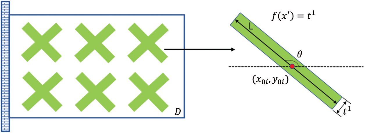
Figure 1: Basic components of MMC-based topology optimization framework [28]
In Fig. 1, as an example, each component comprises 5 design variables and 12 components exist; therefore, the total number of design variables in the design domain is
In the MMC-based topology optimization framework, each component in the prescribed design domain is described by the topology description functions (TDF)
For each component, the TDF can be described as
Based on the description of a single component, the structural topology description in a given design domain can be expressed as follows:
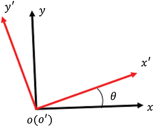
Figure 2: Relationship between local and global coordinates
3 Mathematical Formulation for two Types of Objective Functions
Under the MMC-based topology optimization framework, the general topology optimization problem can be formulated as follows [27]:
For a thermoelastic structural topology optimization, two types of objective function formulations are presented herein that accounts for the combination effects of thermal and mechanical loads based on the MMC framework. The objective functions are the minimum structural compliance and elastic strain energy, respectively. From the comparison of the optimization results of the two optimization objectives, we investigate the physical meanings of the different objective functions and determine an objective function that is more suitable for the topology optimization of thermoelastic structures. The detailed formulations of the two types of objective functions are presented as follows.
3.1 Mathematical Formulation with Minimum Structural Compliance
When minimizing structural compliance with a specified available volume constraint based on the combination of thermal and mechanical loads, the corresponding mathematical formulation can be written as follows:
3.2 Mathematical Formulation with Minimum Elastic Strain Energy
When minimizing elastic strain energy as the objective function with a specified available volume constraint based on the combination of thermal and mechanical loads, the corresponding mathematical formulation can be written as follows:
According to [23], the strain energy in Eq. (7) can also be written as follows:
As shown in Eq. (8),
4 Numerical Implementation Strategies
In this section, the finite element analysis and sensitivity analysis for topology optimization of a thermoelastic structure are presented based on the MMC topology optimization framework.
4.1 Finite Element Analysis of Objective Functions Based on an Ersatz Material Model
The MMC-based topology optimization framework is a boundary evolution-based topology optimization method, and the ersatz material model is typically applied for finite element analysis to enhance computational efficiency. The specified design domain is discretized by four-node bilinear elements; based on the method, the TDF values at four nodes of each element can be calculated as illustrated in Fig. 3.
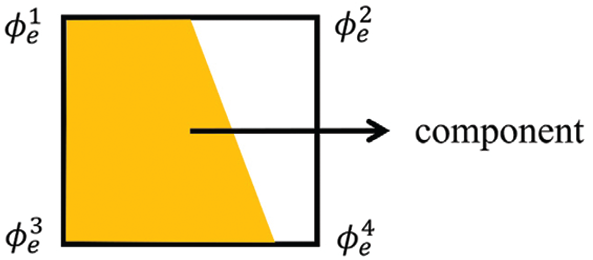
Figure 3: Component occupies the e-th element
Subsequently, the equivalent Young's modulus of an element can be expressed as [28]
The objective function in Eq. (6) (structural compliance) under a combination of thermal and mechanical loads can be discretized into the finite element format as follows:
The thermal load vector
Here,
According to the equilibrium equation,
The objective function in Eq. (7) (structural elastic strain energy) under a combination of thermal and mechanical loads can be discretized into the finite element format as follows:
It is noteworthy that the elastic strain energy
The Eq. (17) can be also written as
For the structure without thermal load
The sensitivity analysis for minimizing the structural compliance and elastic strain energy for the thermoelastic structural topology optimization under the available volume constraint formulated in Eqs. (6) and (7) is presented in this section.
(1) Using minimum structural compliance as an objective function, the sensitivity with respect to the design variables
Meanwhile, according to
Substituting Eq. (20) into Eq. (19) results in
Because
Furthermore,
(2) In case that the minimum elastic strain energy as the objective function, according to Eq. (18), then the sensitivity with respect to the design variable aij can be written as
5 Numerical Examples and Discussions
In this section, a benchmark example is used to verify the effectiveness of the MMC-based framework in topology optimization of thermoelastic structures, and the effects of different objective functions on the structural topology configurations are compared. Furthermore, the physical meaning of the different objective functions is discussed. The design variable updating strategy adopted in this study is the method of moving asymptotes (MMA) [32]. In this section, it is assumed that the structure is in the state of plane stress, the unit of thickness is 1, and the finite element is in the form of a bilinear four-node rectangular element. In the example, the geometrical, material, and load parameters are in dimensionless forms.
5.1 A Two-End Clamped Beam with Only a Mechanical Load
The purpose of this example is to verify the advantages of the proposed topology optimization framework. A two-end clamped beam with
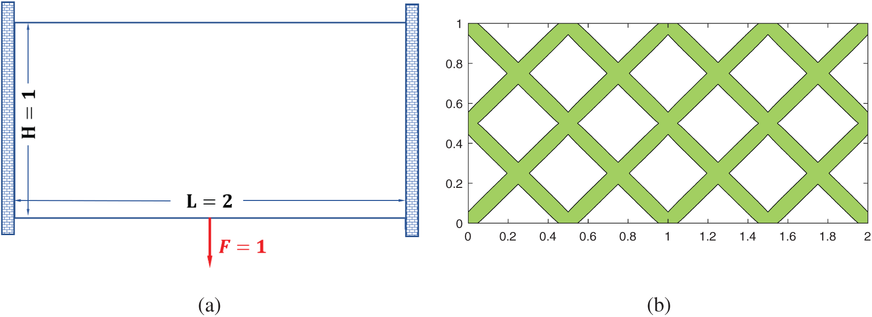
Figure 4: First example: (a) a two-end clamped beam design domain only with a mechanical load, (b) initial building blocks of MMC-based framework
For the design domain, as shown in Fig. 4a, the corresponding optimization problem with only a mechanical load can be solved using an analytical method, which was described in detail by Yan et al. [13]. According to the [13], the corresponding optimal inclined angle of the final two-bar structural topology is

Figure 5: The optimized configurations obtained by different methods. (a) The optimized configuration from MMC-based framework with the compliance
5.2 A Two-End Clamped Beam with Thermo-Mechanical Load
The same two-end clamped beam, as shown in Fig. 4a, with both thermal and mechanical loads, is studied in this example. The structure is subjected to a uniform temperature
Fig. 6a shows the effects of different volume fractions on the optimized topological configurations. As we can observe from Fig. 6a, a two-bar V-shaped configuration of the optimized configurations does not change as the volume fraction increases but the objective function value of the structure decreased gradually as the specified volume fraction increased. However, when the base material of the structure continued to increase, the degree of reduction of the structural compliance became stable gradually, indicating that increasing the material can no longer reduce the compliance of the structure significantly when the volume fractions are greater than 0.4 in this example.
To further investigate the effect of temperature changes on the optimized structural layout, the two-end clamped beam structure with different temperature changes is optimized under the same volume fraction. As shown in Fig. 6b, with the increase of the temperature change, the compliance of the structure is continuously increased, and the optimized topology of structures differs with the increasing temperature. In addition, a sudden transformation of configuration occurs within the temperature changes range of 175∼225, the structural configuration changes from a two-bar V-shaped structure to a three-bar “claw-like” structure. When the temperature is relatively low, the layout of the optimized structure is a two-bar V-shaped because the mechanical load is the dominant load at this time. As the temperature changes increased, the effect of the thermal load becomes more and more prominent, and the optimized configurations changed from a two-bar V-shaped to a three-bar “claw-like” structure. This configuration indicates that the deformation caused by the thermal load and mechanical load offset each other, thereby reducing the work performed by the combination of thermal and mechanical loads and reducing the structural compliance. Furthermore, Fig. 6b illustrates that temperature changes significantly affect the optimized configuration of the thermoelastic structure.
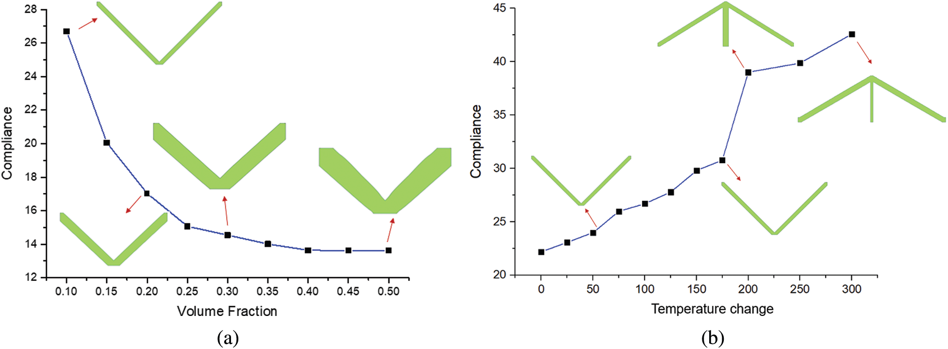
Figure 6: The optimized topological configurations with the objective function of compliance considering thermal and mechanical loads. (a) Effect of different volume fractions on the optimized topological configuration, (b) Effect of temperature changes on the optimized topological configuration
As can be seen from Fig. 6b, the optimized results are both three-bar “claw-like” structures when the temperature changes are 200 and 300, respectively. However, some slight differences exist between the two structures.When the temperature change is 200, the middle rod of the optimized topology structure is thicker and the two inclined bars are thinner. However, when the temperature change is 300, the middle bar of the optimized topology becomes thinner, and the two inclined bars are thicker. This is because the thermal load effect is more obvious in the case of
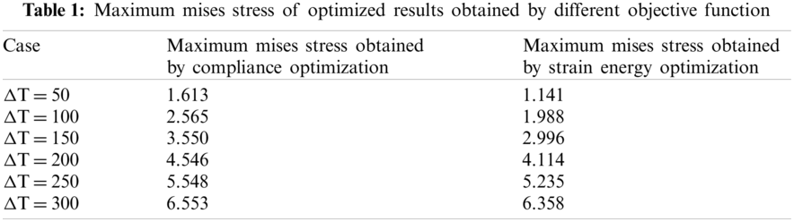
However, the structural compliance represents the total work generated by a specified load (mechanical or thermal load). When a structure is subjected to a mechanical load, the compliance of the structure represents the measurement of the volume and shape changes caused by the mechanical loads. However, when the structure is subjected to a combination of thermal and mechanical loads, the physical meaning of the compliance of the structure is questionable. The structural deformation cannot guarantee to be minimized in this case. Furthermore, from Fig. 7c and Tab. 1, we can observe a relatively high-stress level in the optimized structure, in which the optimized three-bar “claw-like” configuration applies more strict constraint on the structural deformation.
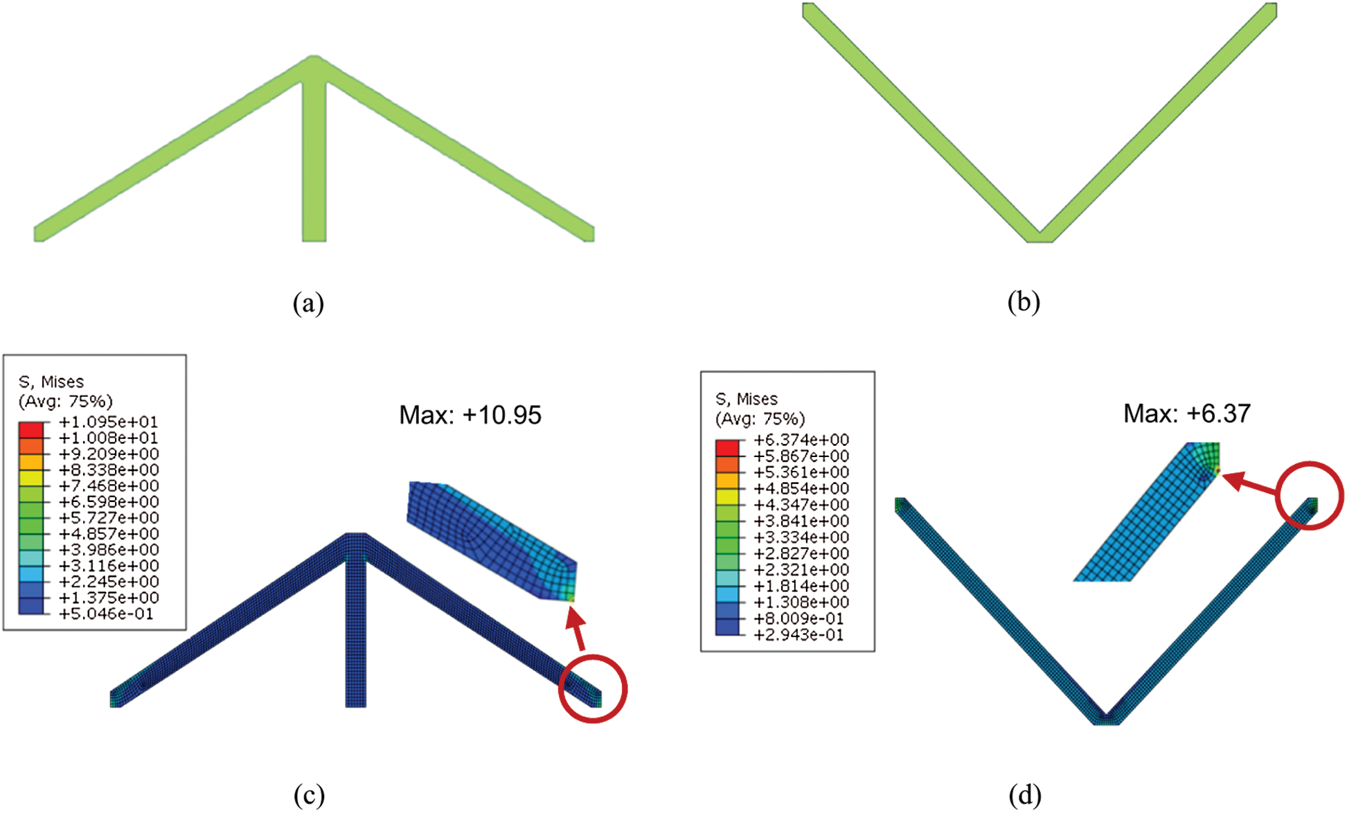
Figure 7: Optimized topological configurations and corresponding Mises stress nephograms obtained by two types of objective functions when
To considering the effects of structural stress, the minimum elastic strain energy is chosen as another type of objective function to obtain the optimized topology of the thermoelastic structure. To compare the different structural configurations obtained by the two types of objective functions at the same temperature changes, the optimized configurations at
The finite element analysis in Figs. 7c and 7d, an 8-node biquadratic element is adopted to ensure the convergence of the Mises stress values of different mesh densities at the same temperature. Fig. 8 shows the effect of temperature changes on the optimized configurations obtained by minimum strain energy optimization. Then it can be seen from Fig. 8 that the optimized configuration based on minimum strain energy always presented a two-bar V-shaped configuration for all the temperature change cases, which is obviously difference with that observed in compliance optimization (changing from a two-bar V-shaped configuration to a three-bar “claw-like” configuration).
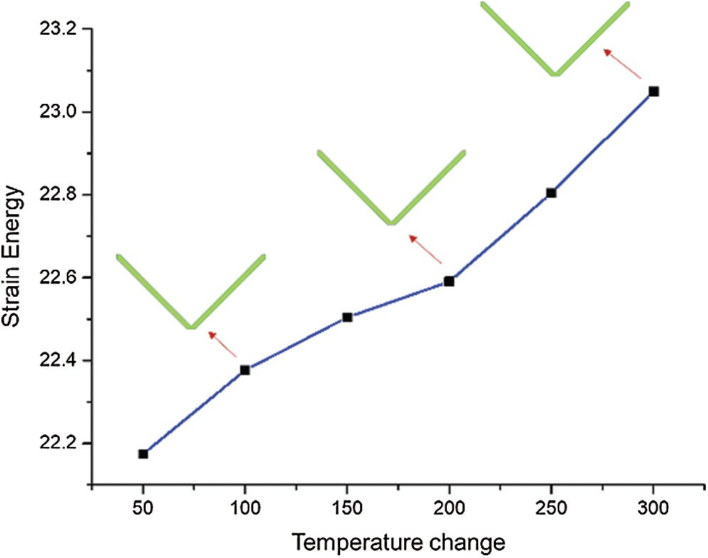
Figure 8: The Effect of temperature on structural strain energy
It is especially pointed that for a better comparison, the mechanical load is set as
Tab. 2 shows the comparison of the maximum displacement values of the two topological configurations obtained based on the two different objective functions at different temperature changes. As show in Tab. 2, when the temperature changes are relatively low, such as
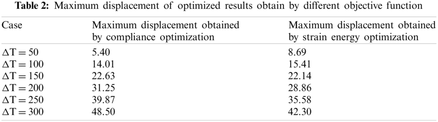
Combined with Tabs. 1 and 2, it can be observed that when the objective function of the minimum strain energy of the structure is used, the maximum Mises stress of the optimized structure is always lower than that from compliance design, while the maximum displacement values of the optimized structure designed with the minimum compliance and that with the minimum strain energy have no consistent magnitude relationship. Therefore, for the topological optimization design of a thermoelastic structure, the physical significance of taking the minimum compliance as the objective function is not clear, and the performance of the optimized configurations obtained is not well predicted.
In the present study, to overcome the challenges of traditional topological optimization methods for addressing thermoelastic topology optimization, the MMC-based topology optimization framework is applied. Topology optimization design is performed using the minimum compliance and minimum strain energy as the objective functions, with a specified available volume constraint. Subsequently, the response of the optimized structural topology under the combination of thermal and mechanical loads is investigated. The topological optimization formulation and the derivation of analytical sensitivity are presented, and the physical meanings of different objective functions are discussed separately. When using the minimum compliance as the objective function for topology optimization design, the thermal load exerted a certain effect on the topological configuration of the structure. The topological configuration of the structure changed from a two-bar V-shaped structure to a three-bar “claw-like” structure. Such a configuration transformation is beneficial to reduce the compliance of the structure but increases the level of stress inside the structure. However, when using the minimum strain energy as the objective function for topology optimization design, there is no topology changing observed as the thermal load increased. This occurred because the minimum strain energy of the structure indicates the stress level of the structure, and the two-bar V-shaped structure obtained from the minimum elastic strain energy formulation is beneficial for relaxing the structural deformation constraints. In addition, the results indicate that by utilizing the minimum strain energy as the objective function, compared with compliance minimization, the structural configurations obtained are more superior in terms of structural strength.
Funding Statement: Financial supports for this research were provided by the National Natural Science Foundation of China (Nos. 11672057, 12002278, U1906233), the National Key R&D Program of China (2017YFC0307201), the Key R&D Program of Shandong Province (2019JZZY010801), the Fundamental Research Funds for the Central Universities (NWPU-G2020KY05308). These supports are gratefully acknowledged.
Conflicts of Interest: The authors declare that they have no conflicts of interest to report regarding the present study
1. Guo, X., Cheng, G. D. (2010). Recent development in structural design and optimization. Acta Mechanica Sinica/Lixue Xuebao, 26(6), 807–823. DOI 10.1007/s10409-010-0395-7. [Google Scholar] [CrossRef]
2. Rozvany, G. I. N. (2009). A critical review of established methods of structural topology optimization. Springer, 37(3), 217–237. DOI 10.1007/s00158-007-0217-0. [Google Scholar] [CrossRef]
3. Sigmund, O., Maute, K. (2013). Topology optimization approaches: A comparative review. Structural and Multidisciplinary Optimization, 48(6), 1031–1055. DOI 10.1007/s00158-013-0978-6. [Google Scholar] [CrossRef]
4. Takezawa, A., Yoon, G. H., Jeong, S. H., Kobashi, M., Kitamura, M. (2014). Structural topology optimization with strength and heat conduction constraints. Computer Methods in Applied Mechanics and Engineering, 276, 341–361. DOI 10.1016/j.cma.2014.04.003. [Google Scholar] [CrossRef]
5. Ni, X. Q., Cheng, G. D. (2015). Optimal design of thin solid elastic plates under thermal load. Applied Mathematics and Mechanics, 36(3), 233–241. DOI 10.3879/j.issn.1000-0887.2015.03.001. [Google Scholar] [CrossRef]
6. Rodrigues, H., Fernandes, P. (1995). A material based model for topology optimization of thermoelastic structures. International Journal for Numerical Methods in Engineering, 38(12), 1951–1965. DOI 10.1002/(ISSN)1097-0207. [Google Scholar] [CrossRef]
7. Sigmund, O., Torquato, S. (1997). Design of materials with extreme thermal expansion using a three-phase topology optimization method. Journal of the Mechanics and Physics of Solids, 45(6), 1037–1067. DOI 10.1016/S0022-5096(96)00114-7. [Google Scholar] [CrossRef]
8. Li, Q., Steven, G. P., Xie, Y. X. (1999) Displacement minimization of thermoelastic structures by evolutionary thickness design. Computer Methods in Applied Mechanics and Engineering, 179(3–4), 361–378. DOI 10.1016/S0045-7825(99)00047-X. [Google Scholar] [CrossRef]
9. Li, Q., Steven, G. P., Xie, Y. M. (2001). Thermoelastic topology optimization for problems with varying temperature fields. Journal of Thermal Stresses, 24(4), 347–366. DOI 10.1080/01495730151078153. [Google Scholar] [CrossRef]
10. Cho, S., Choi, J. Y. (2005). Efficient topology optimization of thermo-elasticity problems using coupled field adjoint sensitivity analysis method. Finite Elements in Analysis and Design, 41(15), 1481–1495. DOI 10.1016/j.finel.2005.05.003. [Google Scholar] [CrossRef]
11. Chung, H., Amir, O., Kim, H. A. (2020). Level-set topology optimization considering nonlinear thermoelasticity. Computer Methods in Applied Mechanics and Engineering, 361, 112735. DOI 10.1016/j.cma.2019.112735. [Google Scholar] [CrossRef]
12. Deng, J., Yan, J., Cheng, G. (2013). Multi-objective concurrent topology optimization of thermoelastic structures composed of homogeneous porous material. Structural and Multidisciplinary Optimization, 47(4), 583–597. DOI 10.1007/s00158-012-0849-6. [Google Scholar] [CrossRef]
13. Yan, J., Guo, X., Cheng, G. (2016). Multi-scale concurrent material and structural design under mechanical and thermal loads. Computational Mechanics, 57(3), 437–446. DOI 10.1007/s00466-015-1255-x. [Google Scholar] [CrossRef]
14. Li, L., Kim, H. A. (2020). Multiscale topology optimization of thermoelastic structures using level set method. AIAA Scitech 2020 Forum, vol. 1. American Institute of Aeronautics and Astronautics Inc., AIAA. Orlando, FL, USA. DOI 10.2514/6.2020-0890. [Google Scholar] [CrossRef]
15. Zhu, X., Zhao, C., Wang, X., Zhou, Y., Hu, P. et al. (2019). Temperature-constrained topology optimization of thermo-mechanical coupled problems. Engineering Optimization, 51(10), 1687–1709. DOI 10.1080/0305215X.2018.1554065. [Google Scholar] [CrossRef]
16. Wu, C., Fang, J., Li, Q. (2019). Multi-material topology optimization for thermal buckling criteria. Computer Methods in Applied Mechanics and Engineering, 346, 1136–1155. DOI 10.1016/j.cma.2018.08.015. [Google Scholar] [CrossRef]
17. Gao, T., Zhang, W. (2010). Topology optimization involving thermo-elastic stress loads. Structural and Multidisciplinary Optimization, 42(5), 725–738. DOI 10.1007/s00158-010-0527-5. [Google Scholar] [CrossRef]
18. Li, L., Du, Z., Kim, H. A. (2020). Design of architected materials for thermoelastic macrostructures using level Set method. JOM, 72(4), 1734–1744. DOI 10.1007/s11837-020-04046-2. [Google Scholar] [CrossRef]
19. Pedersen, P., Pedersen, N. L. (2010). Strength optimized designs of thermoelastic structures. Structural and Multidisciplinary Optimization, 42(5), 681–691. DOI 10.1007/s00158-010-0535-5. [Google Scholar] [CrossRef]
20. Pedersen, P., Pedersen, N. L. (2012). Interpolation/penalization applied for strength design of 3D thermoelastic structures. Structural and Multidisciplinary Optimization, 45(6), 773–786. DOI 10.1007/s00158-011-0755-3. [Google Scholar] [CrossRef]
21. Deaton, J. D., Grandhi, R. V. (2013). Stiffening of restrained thermal structures via topology optimization. Structural and Multidisciplinary Optimization, 48(4), 731–745. DOI 10.1007/s00158-013-0934-5. [Google Scholar] [CrossRef]
22. Deaton, J. D., Grandhi, R. V. (2016). Stress-based design of thermal structures via topology optimization. Structural and Multidisciplinary Optimization, 53(2), 253–270. DOI 10.1007/s00158-015-1331-z. [Google Scholar] [CrossRef]
23. Zhang, W., Yang, J., Xu, Y., Gao, T. (2014). Topology optimization of thermoelastic structures: Mean compliance minimization or elastic strain energy minimization. Structural and Multidisciplinary Optimization, 49(3), 417–429. DOI 10.1007/s00158-013-0991-9. [Google Scholar] [CrossRef]
24. Meng, Q., Xu, B., Wang, C., Zhao, L. (2020). Stress constrained thermo-elastic topology optimization based on stabilizing control schemes. Journal of Thermal Stresses, 43(8), 1040–1068. DOI 10.1080/01495739.2020.1766391. [Google Scholar] [CrossRef]
25. Bruyneel, M., Duysinx, P. (2005). Note on topology optimization of continuum structures including self-weight. Structural and Multidisciplinary Optimization, 29(4), 245–256. DOI 10.1007/s00158-004-0484-y. [Google Scholar] [CrossRef]
26. Xia, Q., Wang, M. Y. (2008). Topology optimization of thermoelastic structures using level set method. Computational Mechanics, 42(6), 837–857. DOI 10.1007/s00466-008-0287-x. [Google Scholar] [CrossRef]
27. Guo, X., Zhang, W., Zhong, W. (2014). Doing topology optimization explicitly and geometrically---A new moving morphable components based framework. Journal of Applied Mechanics, Transactions ASME, 81(8), 1–12. DOI 10.1115/1.4027609. [Google Scholar] [CrossRef]
28. Zhang, W., Yuan, J., Zhang, J., Guo, X. (2016). A new topology optimization approach based on moving morphable components (MMC) and the ersatz material model. Structural and Multidisciplinary Optimization, 53(6), 1243–1260. DOI 10.1007/s00158-015-1372-3. [Google Scholar] [CrossRef]
29. Zhang, W., Li, D., Kang, P., Guo, X., Youn, S. K. (2020). Explicit topology optimization using IGA-based moving morphable void (MMV) approach. Computer Methods in Applied Mechanics and Engineering, 360, 112685. DOI 10.1016/j.cma.2019.112685. [Google Scholar] [CrossRef]
30. Zhang, W., Jiang, S., Liu, C., Li, D., Kang, P. et al. (2020). Stress-related topology optimization of shell structures using IGA/TSA-based moving morphable void (MMV) approach. Computer Methods in Applied Mechanics and Engineering, 366, 113036. DOI 10.1016/j.cma.2020.113036. [Google Scholar] [CrossRef]
31. Takalloozadeh, M., Yoon, G. H. (2017). Implementation of topological derivative in the moving morphable components approach. Finite Elements in Analysis and Design, 134, 16–26. DOI 10.1016/j.finel.2017.05.008. [Google Scholar] [CrossRef]
32. Svanberg, K. (1987). The method of moving asymptotes---A new method for structural optimization. International Journal for Numerical Methods in Engineering, 24(2), 359–373. DOI 10.1002/(ISSN)1097-0207. [Google Scholar] [CrossRef]
33. Deaton, J. D., Grandhi, R. V. (2014). A survey of structural and multidisciplinary continuum topology optimization: Post 2000. Structural and Multidisciplinary Optimization, 49(1), 1–38. DOI 10.1007/s00158-013-0956-z. [Google Scholar] [CrossRef]
34. ABAQUS (2014). ABAQUS v.6.14-2 Commercial FE Software and Documentation. Dassault Systèmes. Simulia Corporation, Providence, RI, USA. [Google Scholar]
 | This work is licensed under a Creative Commons Attribution 4.0 International License, which permits unrestricted use, distribution, and reproduction in any medium, provided the original work is properly cited. |