| Computer Modeling in Engineering & Sciences |
DOI: 10.32604/cmes.2022.015717
ARTICLE
Optimization of the Drag Forces of Shell Janus Micromotor: A Study Based on Hydrodynamical Analysis and Numerical Simulation
Wuhan University of Technology, Wuhan, 430070, China
*Corresponding Author: Zhen Wang. Email: wangzhen@whut.edu.cn
Received: 08 January 2021; Accepted: 08 July 2021
Abstract: Micromotors are widely used in cell operation, drug delivery and environmental decontamination due to their small size, low energy consumption and large propelling power. Compared to traditional Janus micromotor, the shell Janus micromotor has better motion performance. However, the structural optimization of its motion performance is still unclear. The main factor restricting the motion performance of shell Janus micromotors is the drag forces. In the current work, theoretical analysis and numerical simulation were applied to analyze the drag forces of shell Janus micromotors. This study aims to design the optimum structure of shell Janus micromotors with minimum drag forces and obtain the magnitude of drag forces considering both the internal and external fluids of the shell Janus micromotors. Moreover, the influence of the motor geometry and Reynolds number on the drag coefficient was analyzed using numerical simulations. The results provide guidance for the optimum flow velocity, opening diameter and shell thickness to achieve minimum drag force.
Keywords: Shell janus micromotor; drag force; dimensionless numbers
Micromotors are micro-scale devices with small size, low energy consumption and large propelling power. Micromotors are widely used in cell operation, drug delivery and environmental remediation [1–3]. Bubble-driven micromotors are divided into tubular micromotors [4–7], Janus micromotors (Janus particles) [8,9], shell Janus micromotors [10,11] and other irregular micro-swimmers [12,13], according to their shape [14,15]. They have gained more attention due to their excellent motion performances and biological applications.
The catalyst coating on one side of the outer surface of Janus micromotor reacts with the liquid environment to generate bubbles, and pushes it to move to the other side [16,17]. Today, there are many applications for Janus micromotors [18]. However, there are not many studies on shell Janus micromotors with similar shapes. There is a recessed cavity inside the shell Janus micromotor. Compared with a solid Janus micromotor, bubbles are easier to nucleate and grow in the recessed cavity [19]. Shell Janus micromotors are faster and more efficient than the Janus micromotors having a similar geometry [20]. Shell Janus micromotors have also attracted more and more attention from researchers [21]. The micromotor shell moves efficiently in the solution and can perform regular circular or linear movements without external intervention [22]. The microcap-shaped shell Janus micromotor moves at a very fast speed and achieves directional movement under the action of an external magnetic field.
Huang et al. [10] proposed a method for preparing shell Janus micromotors, and found that the shell Janus micromotor performed better than the Janus motor having the same size. This was partly due to the reason that the shell Janus micromotor generated bubbles at a faster rate, though the mechanism is still not fully understood. Safdar et al. [23] designed a three-metal shell Janus micromotor. Zhang et al. [24] designed a jellyfish-shaped micromotor with a shell Janus micromotor combined with a power unit and found that the proposed design exhibited good motion performance. Yi et al. [25] prepared a high-performance shell Janus micromotor with an average diameter of 350 nm and an opening of about 100 nm. It is reported that the shell Janus micromotor directionally delivered drugs to the organism's targeted location [26]. The shell Janus micromotor is also designed as an acoustic micromotor, and can capture and transmit cancerous cells [27]. Su et al. [28] further designed a cartridge-case-like micromotor that could be applied as a pH sensor. Although shell Janus micromotor has exhibited excellent motion performance, the structural optimization of its motion performance is still unclear. Although some studies have shown that the motion performance of the shell Janus micromotor is better than that of the Janus micromotor [10,19]. There is no study on the geometrical structure of the shell Janus micromotor. The difference in the geometrical structures of the shell Janus micromotors inevitably affects their motion performances.
In a previous work, we have reviewed studies focusing on the motion of bubble-driven micromotors [29]. The tubular catalytic micromotors move faster than the Janus (solid or shell) ones. Various factors may account for this phenomenon. The drag forces of different micromotors may be one of the critical factors, and we have optimized the geometrical structure and established a theoretical model for the growth of bubbles of the cone-shaped micromotor [30,31]. The geometrical dimensions dramatically affect the motion performance of the micromotor. The biggest problem restricting the motion performance of the shell Janus micromotor is the drag forces. In this paper, theoretical analysis and numerical simulation were used to analyze the drag forces of the shell Janus micromotor to obtain the optimal structure with minimum drag forces. Therefore, this paper presents a novel method to optimize the drag force of the shell Janus micromotor, and comprehensively considers the influence of Reynolds number, the ratio of shell opening diameter to overall diameter, and the ratio of the shell thickness to diameter.
The paper aims to study the drag forces of the shell Janus micromotor. The drag coefficient of the shell Janus micromotor is used to analyze its drag forces. Moreover, numerical simulation methods were used to calculate the drag coefficient of the shell Janus micromotor under different Reynolds numbers, shell Janus micromotor opening diameters and shell thicknesses.
The shell Janus micromotor moves in the static fluid in many practical applications. However, the theoretical analysis prefers to assume that the shell Janus micromotor is at rest while the fluid flows over it. The conditions of the states are equivalent to each other according to the principle of relativity of motion. Therefore, the coordinate system was fixed on the shell Janus micromotor. The micromotor remained stationary, and fluid flowed through the micromotor (Fig. 1). For the steady state flow, the fluid flowed along X–axis, whereas the YZ coordinate plane was parallel to the cross-section of the opening of the shell Janus micromotor. A spherical coordinate system (r, θ, φ) was also established on the shell Janus micromotor, as shown in Fig. 1.
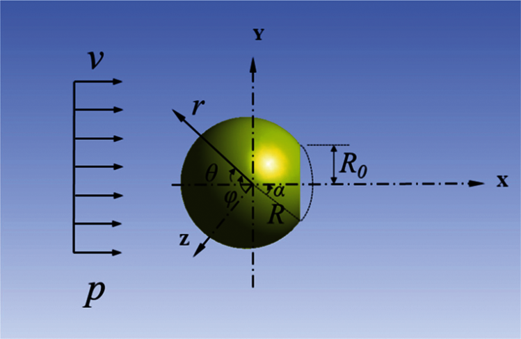
Figure 1: Schematic of the coordinates and the Janus micromotor
In the spherical coordinate system, the Navier–Stokes equation is expressed as Eqs. (1)–(3) [32].
The continuity equation is expressed by Eq. (4).
The Reynolds number (Re) of the fluid flow was very small (Re <<1). Due to this reason, the inertial force was extremely small, and negligible compared to viscous force and pressure gradient term. Therefore, the term
The continuity equation can be written as Eq. (7).
where
Moreover, Eq.(9) can be used to represent the boundary conditions far away from the shell Janus micromotor.
Combining Eqs. (5)–(9) and using the separation variable method to solve the pressure distribution of the flow field around the shell Janus micromotor, set of Eq. (10) is obtained.
The pressure is divided by the surface of the sphere along the area of the sphere. The integral was projected along the flow direction to obtain the drag forces of the shell Janus micromotor, as given by Eq. (11).
The drag forces of a spherical sphere without opening in the fluid are given by Eq. (12).
where the two stress tensor components at the surface are given by Eqs. (13) and (14).
Substituting Eqs. (13) and (14) in Eq.(12), and integrating, Eq.(15) is obtained.
Eq. (15) considers the motor as a complete sphere. Because it is completely symmetrical and the integration area is
In this situation, the Janus micromotor was immersed in the fluid, and the drag force could generally be divided into two categories, namely the form drag and the skin friction drag. The normal stress on the surface of the sphere contributed to the form drag, which is why it was called the pressure drag. The shear stress on the surface of the sphere contributed to the skin friction drag. In this paper, the Janus micromotor moved in a low Reynolds number, which means the skin friction drag force plays a more important role than pressure drag force. This way, the analytical solution of the drag forces of a complete sphere was obtained in the unbounded steady flow.
The integral area of the open spherical shell studied in this paper is given by:
The paper uses the computational fluid dynamics software, Ansys Fluent 18.0, for analyzing the flow field [33]. Ansys Fluent is the fluid simulation software known for its advanced physics modeling capabilities and industry-standard accuracy. It has been validated and is highly regarded for its superior computing power and accurate results that are based on finite volume method. A cuboid was chosen as the calculation area, and the finite volume method was used to discretize the continuous flow field. In addition, a simple method to solve the discrete Navier-Stokes equation was used. Based upon the dimensional analysis, the drag coefficient of the spherical shell in steady flow without boundaries is given by Eq. (17).
The physical parameters related to the movement of shell Janus micromotor in the fluid included drag forces Fd, fluid density ρ, fluid velocity v, spherical shell outer diameter D, opening outer diameter D0, spherical shell thickness d, and fluid viscosity μ. The relationship among these parameters is given by Eq. (18).
The Π-theorem is a commonly used theorem in dimensional analysis [34], and states that if there is a physically meaningful equation involving a certain number (n) of physical variables, then the original equation can be rewritten in terms of a set of ‘p = n − k’ dimensionless parameters Π1, Π2, …,Πp constructed from the original variables (herein n is the total parameters, k is the number of physical dimensions involved, whereas n = 7, and k = 3). Moreover, ρ, v and D are selected as the basic physical parameters. According to the Π-theorem, four independent Π numbers are obtained, which are: Cd, Re, the ratio of shell opening diameter to spherical shell diameter ξ and the ratio of shell thickness to diameter η. Based upon the dimensional analysis, the relationship is given by Eq. (19).
where Re is the Reynolds number of the fluid, ξ=D0/D and is the ratio of the outer diameter of the shell opening to the diameter of the entire sphere, and η=d/D, which is the ratio of the thickness of the shell to the diameter of the sphere. Consequently, the drag coefficient is only related to three dimensionless parameters. When the three parameters above (Re, ξ, η) do not change, the drag forces and drag coefficient of the shell Janus micromotor are fixed.
The drag coefficient is only related to the Reynolds number when the shape of the Janus micromotor is determined (herein, the characteristic length L is the diameter of the Janus sphere), and the Reynolds number is only related to the velocity (v) of the fluid since the density (ρ) and viscosity (μ) of the fluid are fixed according to Eq. (20).
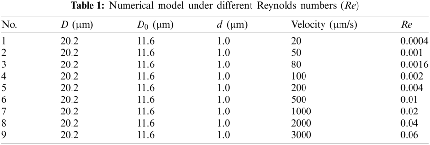
The diameter of the Janus micromotor was 20.2 μm, whereas the opening diameter of the Janus micromotor was 11.6 μm. Moreover, the thickness of the Janus micromotor was 1.0 μm. The fluid medium was water with the density of 998.2 kg/m3 and a viscosity of 1.003 mPa⋅s. At present, the reported maximum speed of the micromotor was 3 mm/s. This paper aimed to simulate the relationship between the drag force and the Reynolds number. The Reynolds number mainly depends on the velocity of a certain fluid. Therefore, it can be divided into nine working conditions, in which, the speed lied within the range of 20–3000 μm/s, as shown by the data presented in Table 1.
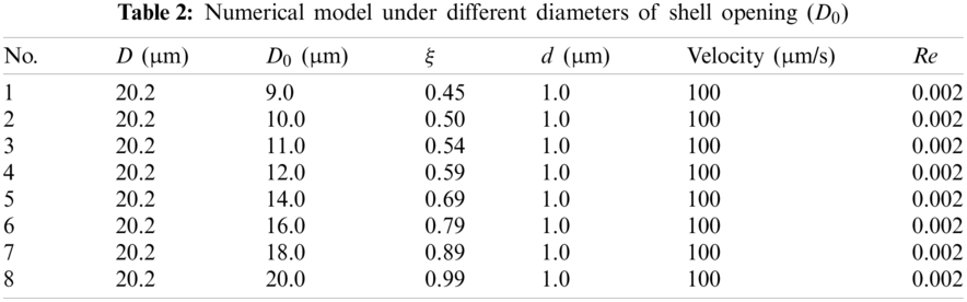
The drag force varies with the value of ξ. When the diameter of the sphere was fixed, the diameter of the opening was sequentially changed, as shown by the data presented in Table 2.
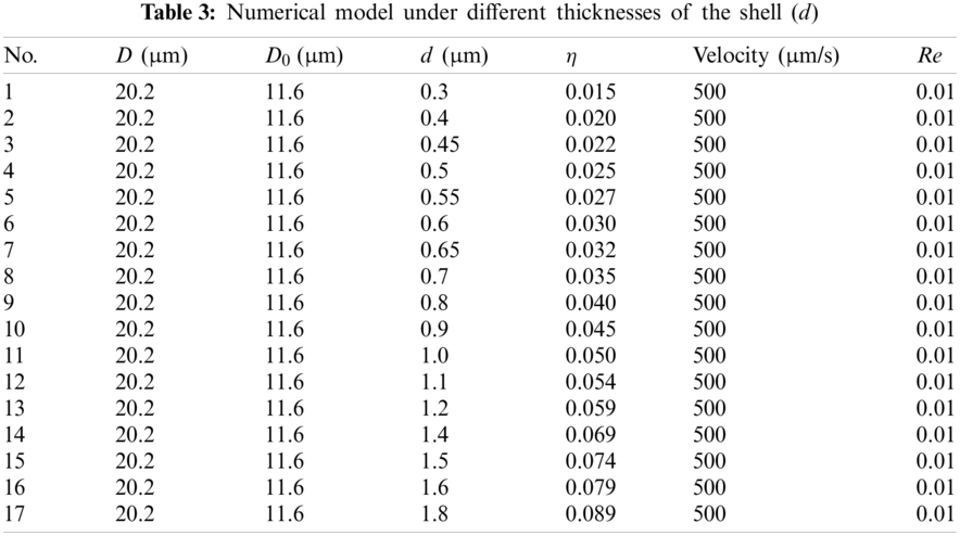
When the diameter of the sphere is fixed, and the thickness of the shell is sequentially changed, the viscosity becomes the most important influencing factor. For such a case, the working conditions are given as the data presented in Table 3.
According to the numerical simulation results, the relationship between the drag forces and drag coefficient under different Reynolds numbers (flow velocity) was drawn in the form of graphs, and the corresponding results are shown in Fig. 2. The drag forces of the Janus micromotor increased linearly with the increase in Reynolds number. When the size and fluid properties (density and viscosity of the fluid) of the Janus micromotor were fixed, the Reynolds number was only related to the fluid velocity. Therefore, the drag force was proportional to the Reynolds number (a). The drag coefficient decreased nonlinearly with the increase in the Reynolds number (b). The graphs show the same variation trends as those of the tubular micromotor in our earlier research [35]. The drag forces were directly proportional to Re (fluid velocity). Furthermore, the drag coefficient was inversely proportional to Re (fluid velocity).
Figure 2: Relationship between drag forces and drag coefficient under different Reynolds numbers (a) drag forces curve (b) drag coefficient curve
The Stokes correlation provided the drag forces of the sphere [36] and is given by Eq. (21).
The drag force of a hollow sphere is 2/3 of that of a solid sphere. Therefore, the drag force of the shell is given by Eq. (22).
The drag coefficient of the hollow spherical shell is given by Eq. (23).
where A is the projected cross-sectional area of the body perpendicular to the flow direction. The value of A can be obtained from Fig. 1 (A = πD2/4, where D is the spherical outer diameter of the Janus micromotor).
3.2 Ratio of the Shell Opening Diameter to the Entire Ball Diameter (ξ)
Fig. 3 shows the relationship between the drag forces and the parameter ξ. The relationship between the drag forces and the shell opening was found not to be monotonous. The drag force was minimal when the value of ξ lied within the range of 0.5–0.6.
Figure 3: Drag force for various values of ξ
In order to study the influence of the opening diameter on the flow field, the shell micromotor geometry was decomposed into components. The shell Janus micromotor was mainly composed of an outer shell, an inner shell and an opening, as shown in Fig. 4. Moreover, the values of drag force on each surface are presented in Fig. 5.
Figure 4: Schematic of the faces attached to the shell Janus micromotor
The results in Fig. 5 show that the drag forces from the outer shell are the main force when the opening diameter is very small. The drag forces from the outer shell and the mouth increase when the opening diameter increased. When the opening size is larger than 12 μm, the drag force from the outer shell starts to fall off, while the drag force from the inner shell and the mouth is likely to go on rising. As we have already mentioned above, when the micromotor moves at low Reynolds number, the skin friction drag plays a greater role than the pressure drag. From the small picture in Fig. 5, it is very clear that the friction drag force is the major part of the drag force on the outer shell.
Figure 5: Drag forces on each surface of the micromotors with different openings
The results show that the opening size had a significant influence on the drag force for different surfaces. Assuming that the direction of the fluid flow was along the positive X-axis, when the surface pressure of the shell was positive, the direction of the drag force was along the negative direction of X-axis. When the surface pressure of the shell was negative, the direction of the drag force was along the positive direction of the X-axis. When the opening was very small (9 μm), the drag forces of the entire spherical shell mainly originated from the outer shell, as shown in Fig. 6a. Therefore, the pressure on the front side was relatively high. The drag force formed by the shear stress on the front surface of the spherical shell was relatively high, and accounted for 76% of the total resistance. The negative pressure at the opening was in the same direction as the incident flow, which increased the overall drag forces.
When the diameter of the opening gradually increased from 9.0 μm (Fig. 6a) to 12.0 μm (Fig. 6b), the pressure on the front surface increased. Therefore, the drag force on the outer shell increased from 3.53 × 10⁻¹¹ N to 4.19 × 10⁻¹¹ N. However, the pressure on the opening and the inner wall became positive, which led to a force opposite to drag. Due to this reason, the total drag force of the Janus micromotor decreased. When the opening diameter was further increased to 16.0 μm (Fig. 6c), the large opening caused the entire flow field to form a negative pressure on the three shell surfaces. The drag force mainly originated from the inner shell, and accounted for 72% of the total drag forces. With the increase in the opening diameter, the drag force generated by the inner shell increased. Therefore, the drag force of the overall structure first decreased, and then, increased with the increase in the opening diameter. If the opening was too small, the influence of the inner shell surface and the opening on the entire flow field could be ignored. If the opening was too large, the backflow would increase the pressure of the inner wall, and the drag forces were mainly provided by the component of the inner wall pressure along the wall area in the flow direction.
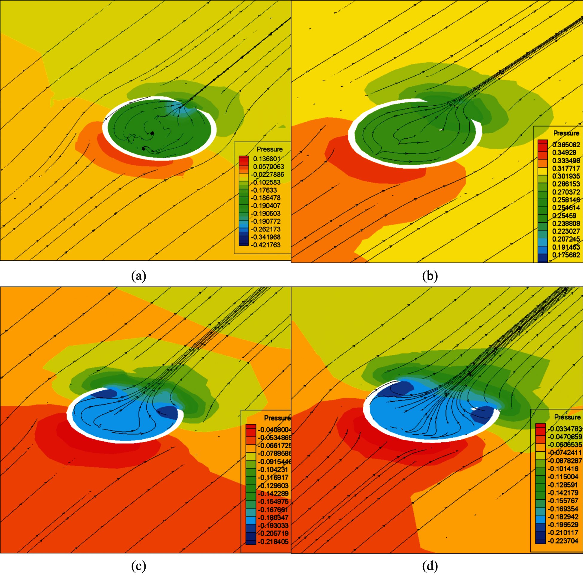
Figure 6: Cross-sectional pressure contours and streamlines at different openings (a) 9.0 μm (b) 12.0 μm (c) 16.0 μm (d) 20.0 μm
The pressure contours on the back and front of the spherical shell were similar to the pressure contour on the cross-section of the spherical shell (Fig. 7). When the opening radius was very small and the pressure on the front face of the spherical shell was positive, the drag force was positive. The pressure at the opening and the inner shell were both negative, which increased the drag forces of the entire spherical shell. When the opening radius was increased to 12.0 μm, the pressure at the opening and the inner shell could offset a part of the drag forces on the front face, and resulted in a decrease in the overall drag forces of the spherical shell. When the opening was further increased, the negative pressure at the opening and the inner shell also increased, causing the overall drag forces of the shell Janus micromotor to increase.
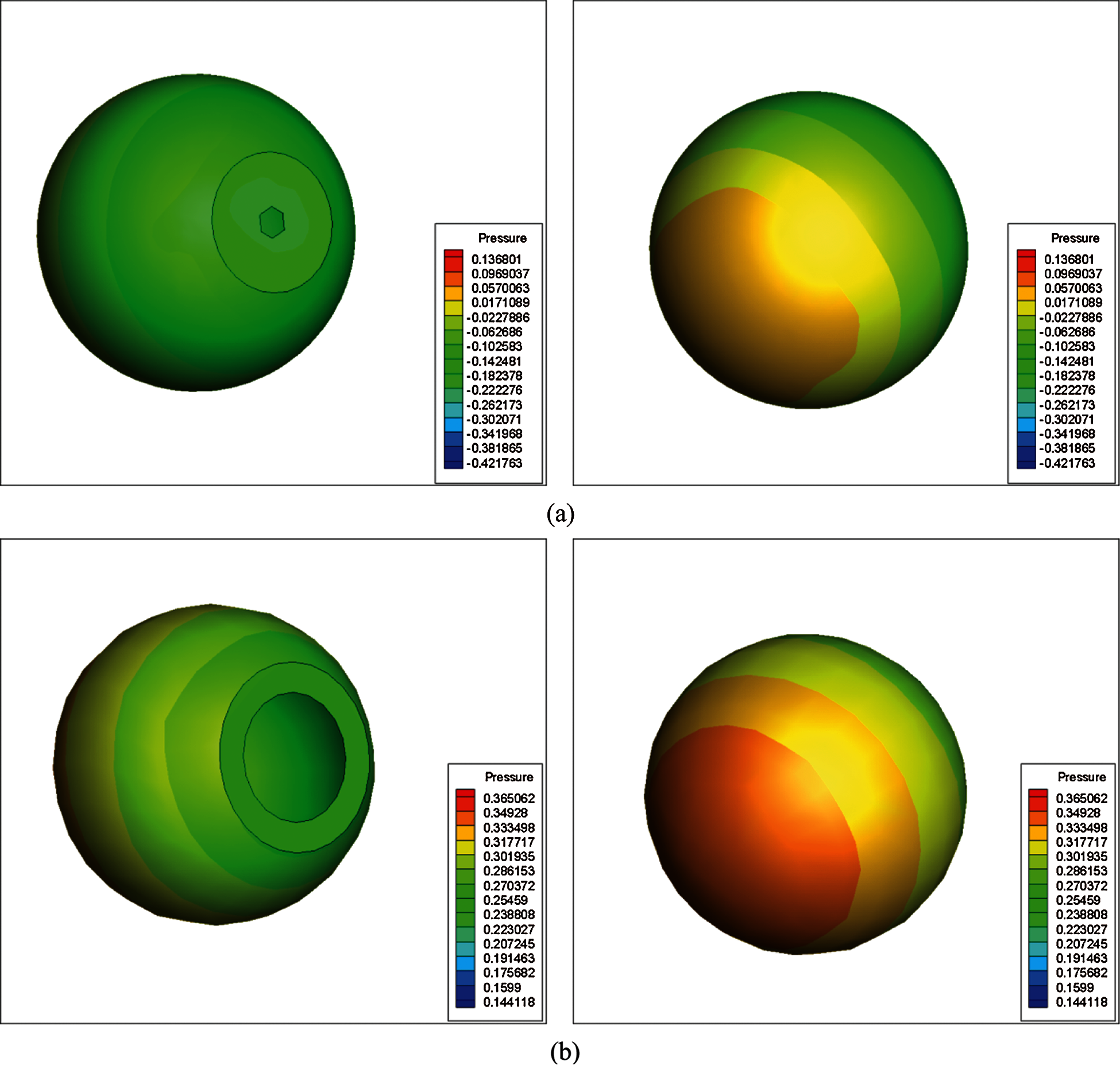
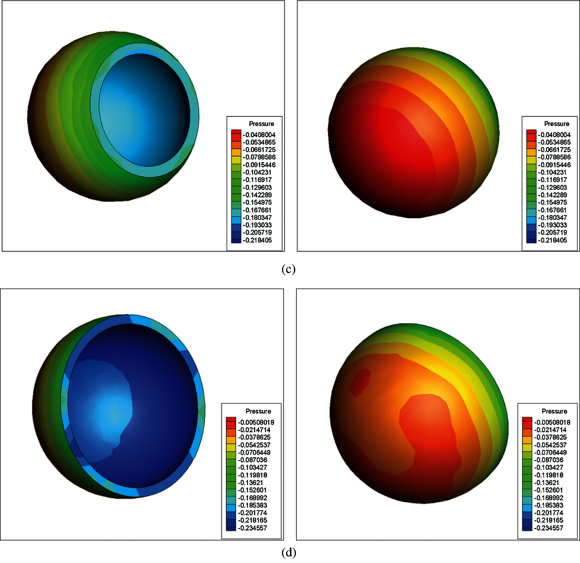
Figure 7: Pressure contours on the back and front of the shell for different openings (a) 9.0 μm (b) 12.0 μm (c) 16.0 μm (d) 20.0 μm
The variation in drag coefficient with the value of ξ is shown in Fig. 8. Based upon Eq. (23), the relationship between the drag coefficient and drag force can be understood. The density ρ and the velocity of the fluid were the same, whereas different values of ξ only meant different openings. The parameter A in Eq. (23) was the projected cross–sectional area, which was the same when the openings of the Janus micromotor were changed. Therefore, the drag coefficient changed in accordance with the drag forces curve. This is because the variation in opening diameter had a negligible effect on the projected cross–sectional area of the shell Janus micromotor.

Figure 8: Drag coefficient for different values of ξ
3.3 Ratio of the Shell Thickness to Sphere Diameter (η)
Fig. 9 shows the relationship between the drag force and drag coefficient for various shell thicknesses. The spherical shell thickness lied within the range of 0.5–0.6 μm (the value of η lied within the range of 0.025–0.03), and the drag force was the highest. For the thickness values of 0.5, 0.55, 0.6, 0.3, 1.2 and 1.6 μm (where the resistance values at both the ends were at the average position), the corresponding values of η were 0.015, 0.025, 0.027, 0.03, 0.059, and 0.08, respectively.
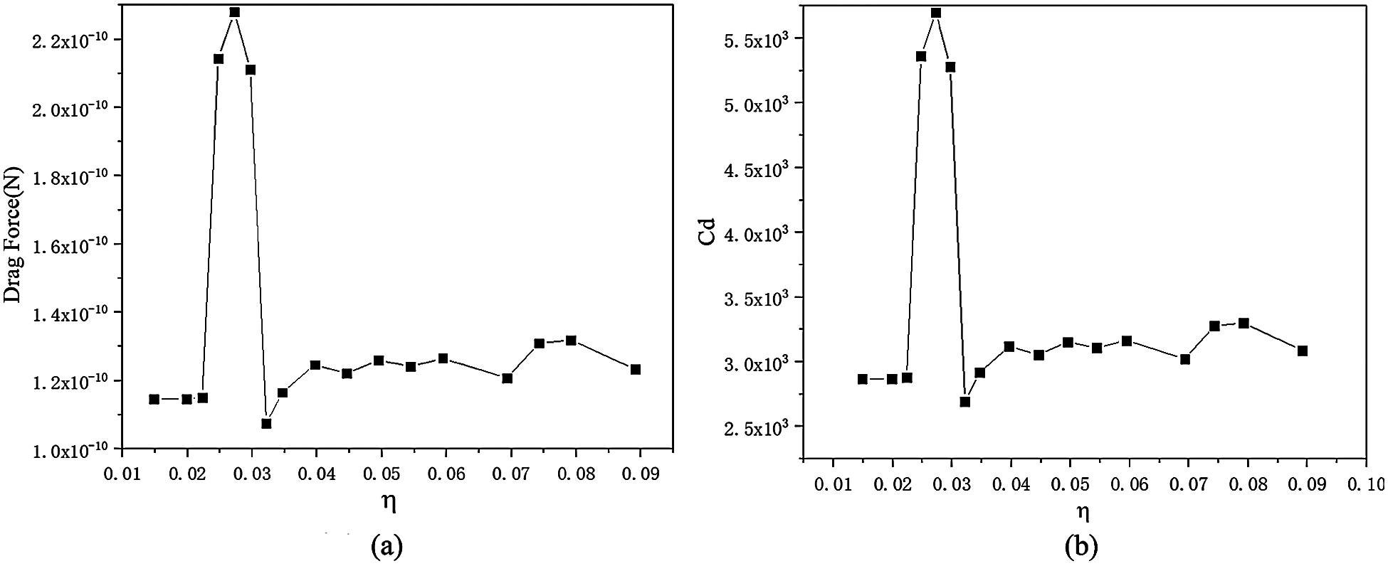
Figure 9: Drag force and drag coefficient for various values of η (a) drag forces curve (b) drag coefficient curve
The pressure contour and velocity contour around the shell Janus micromotor under these conditions were analyzed in detail. The velocity contour diagrams of the spherical shell along the flow direction on the transverse plane under different spherical shell thicknesses are shown in Fig. 10. When the spherical shell was very thin (for the thickness of 0.3 μm, as shown in Fig. 10a), the fluid velocity inside the spherical shell was zero. The results show that, when the spherical shell was very thin, the fluid did not completely fill the inner shell. When the thickness of the shell Janus micromotor was increased to 0.5 μm (Fig. 10b), the fluid in the inner shell began to flow back. Therefore, the flow velocity of the inner shell became positive. When the thickness of the shell Janus micromotor increases from 0.5 to 0.55 μm (Fig. 10c), the reverse flow velocity increased, but the backflow area became smaller. The backflow velocity of the inner shell became smaller when the thickness of the spherical shell was increased to 0.6 μm (Fig. 10d). Even in this case, the backflow area became larger. When the thickness of the spherical shell was further increased, the flow velocity of the fluid in the inner shell of Figs. 10e–10f became negative. That means the fluid in the inner shell no longer formed backflow. These results show that the thickness of the spherical shell had a significant influence on the flow field.
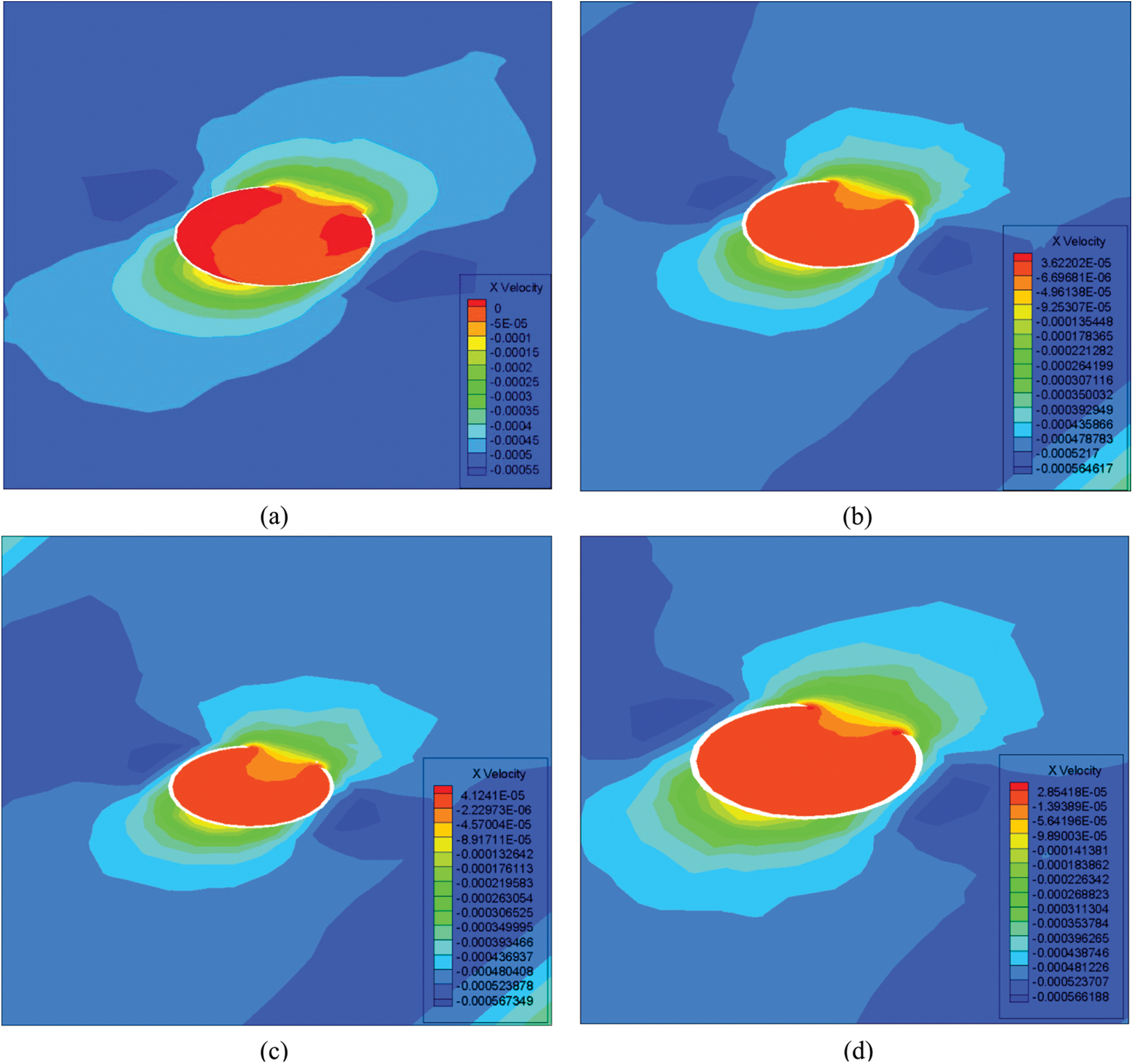
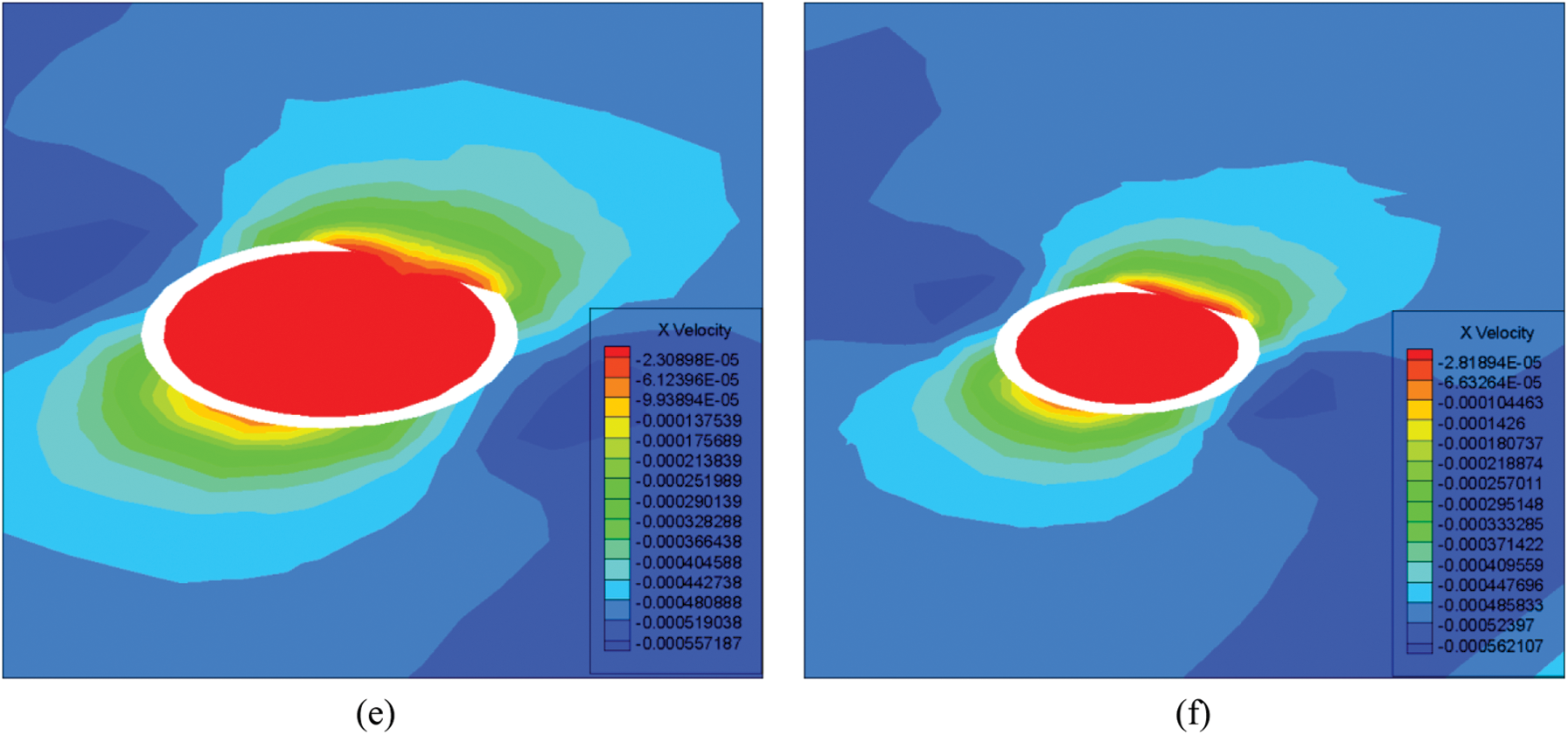
Figure 10: Flow velocity contours at the cross-section under different spherical shell thicknesses (a) 0.3 μm (b) 0.5 μm (c) 0.55 μm (d) 0.6 μm (e) 1.2 μm (f) 1.6 μm
The pressure contour at the opening of the spherical shell was extracted to further analyze the effect of thickness of the shell on drag forces, as shown in Fig. 11. First of all, the front side of the shell Janus micromotor was subjected to positive pressure in the fluid, and the drag force of the shell was generated. When the spherical shell was relatively thin (0.3 μm), as shown in Fig. 11a, the pressure at the opening was positive. Although the pressure at the opening and the pressure on the front side were both positive, their directions were opposite to each other. Therefore, the positive pressure at the opening would reduce the drag forces to a certain extent. When the thickness of the spherical shell was increased to 0.5 μm (Fig. 11b), the pressure at the opening became negative. In the overall coordinate system, the negative pressure at the opening increased the total drag forces of the motor. Figs. 11c and 11d also verify this conclusion. Therefore, within this thickness range, the drag forces of the motor showed an increasing trend. When the thickness of the spherical shell was further increased to 1.2 μm and 1.6 μm, a negative pressure area was observed at the opening. However, both the negative pressure and the area occupied were small, and the overall integral reduced the drag forces. Therefore, the drag force curve shows a sudden increasing trend near the thickness of 0.5–0.6 μm.
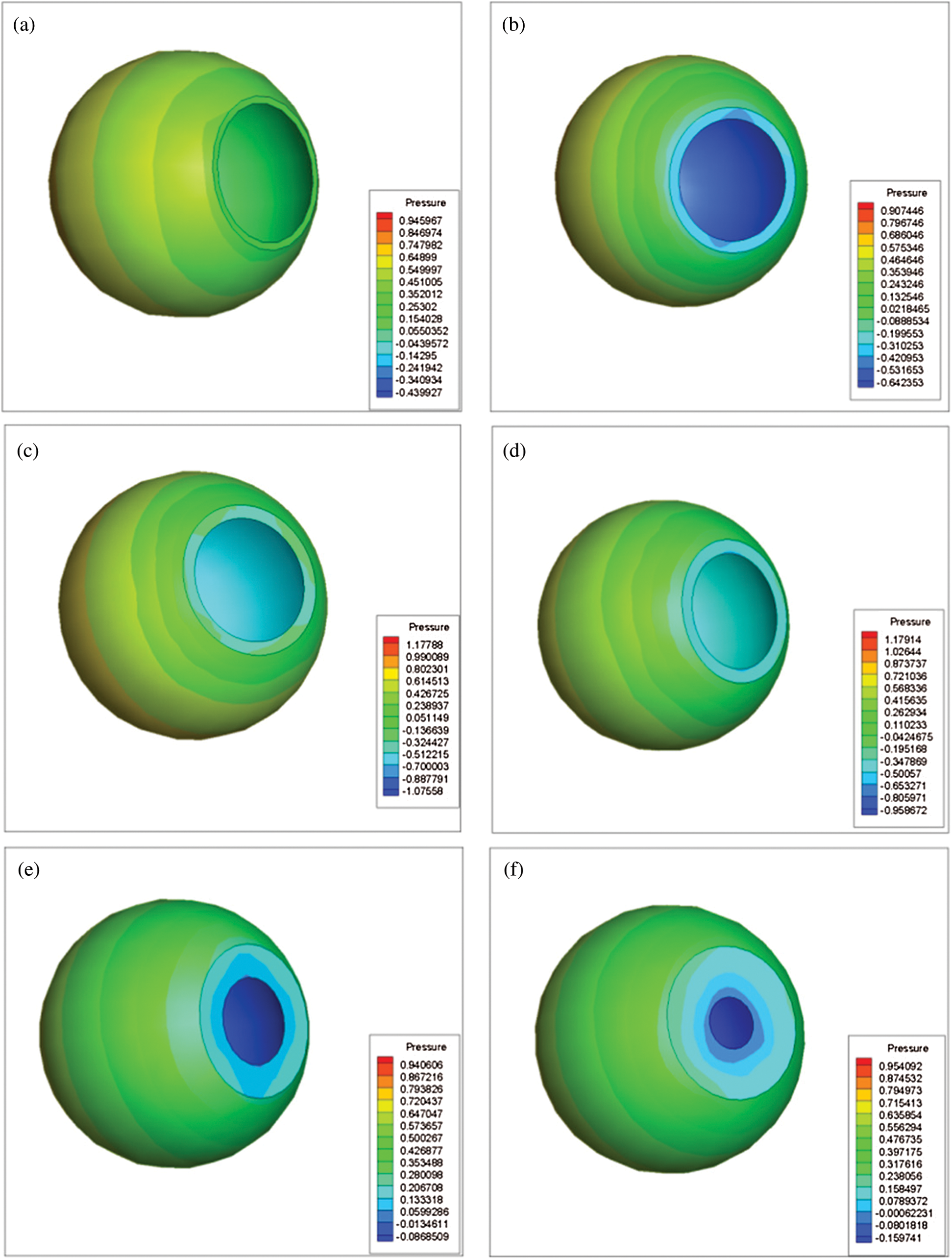
Figure 11: Pressure contours at the opening of the spherical shell under different shell thicknesses (a) 0.3 μm (b) 0.5 μm (c) 0.55 μm (d) 0.6 μm (e) 1.2 μm (f) 1.6 μm
In this paper, the drag forces of the shell Janus micromotor immersed in a fluid flow were obtained using theoretical analysis. Based upon numerical simulation, the relationships between the drag coefficient of the shell Janus micromotor and its geometrical structure, flow velocities were obtained considering the external and internal fluids of the shell Janus micromotor. The drag force was found to be proportional to the Reynolds number. The drag coefficient decreased nonlinearly with the increase in Reynolds number. The drag force was minimum when the value of ξ lied within the range of 0.5–0.6. The overall drag coefficient increased with the increase in the value of η. When the drag force lied within the range of 0.025–0.03, there was a sharp increase in the value of drag force, which took the value to its maximum.
The relationship between the size of the opening and the drag forces of the shell Janus micromotor was not monotonous. Instead, the relationship first decreased, and then, increased. The results also showed that the drag force reached a minimum value when ξ lied within the range of 0.5–0.6. The thickness of the shell should be such that it improves the overall performance of the motion of the shell Janus micromotor. This provides a basis for the practical application of shell Janus micromotors. The value of ξ used in the literature is 0.57, which lies within the range of 0.5–0.6. This shows that the proposed shell Janus micromotor does fulfill this criterion. These results show that the thickness of the shell Janus micromotor has a great influence on the micromotor's motion performance. Therefore, it is necessary to consider the thickness of the shell to reduce the drag force of the shell Janus micromotor.
Interestingly, it was also found that small eddy currents and correspondingly negative pressure areas were generated inside the shell Janus micromotor. The phenomenon is one of the critical factors affecting the overall drag forces of the shell Janus micromotor. The results of the study have a certain guiding significance on the future production of spherical shell Janus micromotors.
Firstly, hydrodynamic analysis was used to establish a theoretical model for the shell Janus micromotor. Then, numerical simulation was used to design a structure that minimized the drag forces of the shell Janus micromotor. The results showed that a corresponding negative pressure zone was generated inside the shell Janus micromotor, which may be the potential mechanism for the change of drag forces. The relationships between the drag forces of the shell Janus micromotor and various other factors, such as Re, ξ, and η were studied. The results helped in obtaining the optimum flow velocity, shell opening diameter and shell thickness to minimize the drag forces of the shell Janus micromotor.
Acknowledgement: The authors would like to thank the editor and the anonymous reviewers for their constructive comments and valuable suggestions to improve the quality of the article.
Author Contributions: Zhen Wang conceived the methods and the framework of the articles. Qiang Wang contributed towards the calculations, completed the numerical simulations and drafted the manuscript.
Funding Statement: This research was financially supported by the Fundamental Research Funds for the Central Universities (WUT: 2019III075GX), and the Open Foundation of Hubei Key Laboratory of Theory and Application of Advanced Materials Mechanics (Grant No. TAM201813).
Conflicts of Interest: The authors declare that they have no conflicts of interest to report regarding the present study.
1. Yoshizumi, Y., Okubo, K., Yokokawa, M., Suzuki, H. (2016). Programmed transport and release of cells by self-propelled micromotors. Langmuir, 32, 9381–9388. DOI 10.1021/acs.langmuir.5b04206. [Google Scholar] [CrossRef]
2. Li, J., Angsantikul, P., Liu, W., Esteban-Fernández de Ávila, B., Thamphiwatana, S. et al. (2017). Micromotors spontaneously neutralize gastric acid for ph–responsive payload release. Angewandte Chemie International Edition, 56(8), 2156–2161. DOI 10.1002/ange.201611774. [Google Scholar] [CrossRef]
3. Eskandarloo, H., Kierulf, A., Abbaspourrad, A. (2017). Nano- and micromotors for cleaning polluted waters: Focused review on pollutant removal mechanisms. Nanoscale, 9, 13850–13863. DOI 10.1039/C7NR05494G. [Google Scholar] [CrossRef]
4. Solovev, A. A., Wang, X., Gracias, D. H., Harazim, S. M., Christoph, D. et al. (2012). Self–propelled nanotools. ACS Nano, 6(2), 1751–1756. DOI 10.1021/nn204762w. [Google Scholar] [CrossRef]
5. Sanchez, S., Solovev, A. A., Harazim, S. M., Deneke, C., Mei, Y. F. et al. (2011). The smallest man–made jet engine. The Chemical Record, 11, 367–370. DOI 10.1002/tcr.201100010. [Google Scholar] [CrossRef]
6. Mei, Y. F., Solovev, A. A., Sanchez, S., Schmidt, O. G. (2011). Rolled–up nanotech on polymers: From basic perception to self-propelled catalytic microengines. Chemical Society Reviews, 40(5), 2109–2119. DOI 10.1039/c0cs00078g. [Google Scholar] [CrossRef]
7. Klingner, A., Islam, S. M., Veronika, M., Vladimir, M. F., Oliver, G. S. et al. (2017). Modeling of unidirectional–Overloaded transition in catalytic tubular microjets. Journal of Physical Chemistry C, 121(27), 14854–14863. DOI 10.1021/acs.jpcc.7b02447. [Google Scholar] [CrossRef]
8. Gao, W., Mattia, D., Victor, G., Jahir, O., Joseph, W. et al. (2013). Multi–fuel driven janus micromotors. Small, 9(3), 467–471. DOI 10.1002/smll.201201864. [Google Scholar] [CrossRef]
9. Wu, Y., Wu, Z., Lin, X., He, Q., Li, J. et al. (2012). Autonomous movement of controllable assembled janus capsule motors. ACS Nano, 6(12), 10910–10916. DOI 10.1021/nn304335x. [Google Scholar] [CrossRef]
10. Huang, W., Manjare, M., Zhao, Y. (2013). Catalytic nanoshell micromotors. Journal of Physical Chemistry C, 117(41), 21590–21596. DOI 10.1021/jp4080288. [Google Scholar] [CrossRef]
11. Lin, Z., Wu, Z., Lin, X., He, Q. (2016). Catalytic polymer multilayer shell motors for separation of organics. Chemistry, 22(5), 1587–1591. DOI 10.1002/chem.201503892. [Google Scholar] [CrossRef]
12. Sangwon, K., Famin, Q., Samhwan, K., Ali, G., Cheil, M. et al. (2013). Fabrication and characterization of magnetic microrobots for three–dimensional cell culture and targeted transportation. Advanced Materials, 25(41), 5863–5868. DOI 10.1002/adma.201301484. [Google Scholar] [CrossRef]
13. Zhu, W., Li, J. X., Leong, Y. J., Rozen, I., Qu, X. et al. (2015). 3D–printed artificial microfish. Advanced Materials, 27(30), 4411–4417. DOI 10.1002/adma.201501372. [Google Scholar] [CrossRef]
14. Lin, X., Wu, Z., Wu, Y., Xuan, M., He, Q. (2016). Self–propelled micro–/nanomotors based on controlled assembled architectures. Advanced Materials, 28(6), 1060–1072. DOI 10.1002/adma.201502583. [Google Scholar] [CrossRef]
15. Gao, W., Wang, J. (2014). Synthetic micro/nanomotors in drug delivery. Nanoscale, 6(18), 10486–10494. DOI 10.1039/C4NR03124E. [Google Scholar] [CrossRef]
16. Gao, W., Feng, X., Pei, A., Gu, Y., Li, J. et al. (2013). Seawater–driven magnesium based janus micromotors for environmental remediation. Nanoscale, 5(11), 4696. DOI 10.1039/c3nr01458d. [Google Scholar] [CrossRef]
17. Manjare, M., Yang, B., Zhao, Y. P. (2012). Bubble driven quasioscillatory translational motion of catalytic micromotors. Physical Review Letters, 109(12), 128305. DOI 10.1103/PhysRevLett.109.128305. [Google Scholar] [CrossRef]
18. Chen, C., Emil, K., Li, J., Fernando, S., Roxanne, C. (2016). Transient micromotors that disappear when no longer needed. ACS Nano, 10(11), 10389–10396. DOI 10.1021/acsnano.6b06256. [Google Scholar] [CrossRef]
19. Zhao, G., Pumera, M. (2014). Geometric asymmetry driven janus micromotors. Nanoscale, 6(19), 11177–11180. DOI 10.1039/C4NR02393E. [Google Scholar] [CrossRef]
20. Ma, X., Jang, S., Popescu M, N. (2016). Reversed janus micro/Nanomotors with internal chemical engine. ACS Nano, 10(9), 8751–8759. DOI 10.1021/acsnano.6b04358. [Google Scholar] [CrossRef]
21. Lin, Z., Wu, Z., Lin, X., He, Q. (2016). Catalytic polymer multilayer shell micromotors for separation of organics. Chemistry–A European Journal, 22(5), 1587–1591. DOI 10.1002/chem.201503892. [Google Scholar] [CrossRef]
22. Keller, S., Teora, S. P., Hu, G. X. (2018). High–throughput design of biocompatible enzyme–based hydrogel microparticles with autonomous movement. Angewandte Chemie International Edition, 130, 9962–9965. DOI 10.1002/ange.201805661. [Google Scholar] [CrossRef]
23. Safdar, M., Itkonen, T., Janis, J. (2015). Bubble–propelled trimetallic microcaps as functional catalytic micromotors. RSC Advances, 5(17), 13171–13174. DOI 10.1039/C4RA16589F. [Google Scholar] [CrossRef]
24. Zhang, X., Cheng, C., Wu, J., Ju, H. (2019). Bubble–Propelled jellyfish–like micromotors for DNA sensing. ACS Applied Materials & Interfaces, 11, 13581–13588. DOI 10.1021/acsami.9b00605. [Google Scholar] [CrossRef]
25. Yi, D., Zhang, Q., Liu, Y., Song, J., Tang, Y. (2016). Synthesis of chemically asymmetric silica nanobottles and their application for cargo loading and as nanoreactors and nanomotors. Angewandte Chemie International Edition, 55(47), 14733–14737. DOI 10.1002/anie.201607330. [Google Scholar] [CrossRef]
26. de Ávila, E. F., Angsantikul, P., Li, J., Lopez-Ramirez, M. A., Ramírez-Herrera, D. E. et al. (2017). Micromotor–enabled active drug delivery for in vivo treatment of stomach infection. Nature Communications, 8(1), 272. DOI 10.1038/s41467-017-00309-w. [Google Scholar] [CrossRef]
27. Fernando, S., Gregory, L. W., Victor, G., Kyle, T. G., Deepak, R. L. et al. (2016). Acoustically propelled nanoshells. Nanoscale, 8(41), 17788–17793. DOI 10.1039/C6NR06603H. [Google Scholar] [CrossRef]
28. Su, Y. J., Ge, Y., Liu, L. M., Zhang, L. N., Liu, M. (2016). Motion–Based pH sensing based on the cartridge–case–like micromotor. ACS Applied Materials & Interfaces, 8(6), 4250–4257. DOI 10.1021/acsami.6b00012. [Google Scholar] [CrossRef]
29. Liu, L., Bai, T., Chi, Q., Wang, Z., Xu, S. et al. (2017). How to make a fast, efficient bubble–driven micromotor: A mechanical view. Micromachines, 8(9), 267. DOI 10.3390/mi8090267. [Google Scholar] [CrossRef]
30. Wang, Z., Chi, Q., Liu, L., Liu, Q., Bai, T. et al. (2017). A viscosity–based model for bubble–propelled catalytic micromotors. Micromachines, 8(7), 198. DOI 10.3390/mi8070198. [Google Scholar] [CrossRef]
31. Lin, Y., Geng, X., Chi, Q., Wang, C., Wang, Z. (2019). Driving forces of the bubble–Driven tubular micromotor based on the full life–cycle of the bubble. Micromachines, 10(6), 415. DOI 10.3390/mi10060415. [Google Scholar] [CrossRef]
32. Wu, W. Y. (1982). Fluid mechanics, pp. 255–265. Beijing: Peking University Press. [Google Scholar]
33. ANSYS, Inc. (2013). ANSYS Fluent Theory Guide 18.0. http://www.pmt.usp.br/academic/martoran/notasmodelosgrad/ANSYS%20Fluent%20Theory%20Guide%2015.pdf. [Google Scholar]
34. Curtis, W. D., Logan, J. D., Parker, W. A. (1982). Dimensional analysis and the pi theorem. Linear Algebra and its Applications, 47, 117–126. DOI 10.1016/0024-3795(82)90229-4. [Google Scholar] [CrossRef]
35. Wang, Z., Chi, Q., Bai, T., Wang, Q., Liu, L. (2018). A dynamic model of drag force for catalytic micromotors based on navier–stokes equations. Micromachines, 9(9), 459. DOI 10.3390/mi9090459. [Google Scholar] [CrossRef]
36. Happel, J., Brenner, H. (1973). Low reynolds number hydrodynamics, with special applications to particulate media, Second revised Edn., pp. 123–129. Leyden: Noordhoff International Publishing. [Google Scholar]
 | This work is licensed under a Creative Commons Attribution 4.0 International License, which permits unrestricted use, distribution, and reproduction in any medium, provided the original work is properly cited. |