| Computer Modeling in Engineering & Sciences |
DOI: 10.32604/cmes.2022.017313
ARTICLE
Melting Characteristics of a Phase Change Material Mixed with Nano Particles of Cobalt Oxide Bounded in a Trapezoidal Structure
1Department of Basic Sciences and Related Studies, Mehran University of Engineering and Technology, Jamshoro, Pakistan
2School of Mechanical and Aerospace Engineering, Nanyang Technological University, Singapore
3Department of Mathematics, Govt Postgraduate College Layyah, Punjab, Pakistan
*Corresponding Author: Sajjad Hussain. Email: sajjadgut@gmail.com
Received: 30 April 2021; Accepted: 29 June 2021
Abstract: A novel trapezoidal design for storage of heat energy through melting of phase-change material (PCM) is investigated. Latent heat thermal energy storage system (LHTES) is a promising option to diminish mis-match between energy consumption and supply. For this purpose, Paraffin: Rubitherm-35 (RT35) material is successively melted in aluminum structure which is heated from one side and the other sides are kept adiabatic. Melting of PCM is observed experimentally and melt fronts are photographed for various time lengths. The fluid-solid module in COMSOL Multiphysics 5.4 has been utilized. The transient heat conduction with enthalpy function is hired. Simulations are carried out for enhancement of thermal conductivity through addition of nano-entities of cobalt oxide
Keywords: Trapezoidal enclosure; nano entities; heat transfer; phase change material COMSOL multiphysics 5.4; numerical simulation
Nomenclature
| U | Velocity |
| Stress tensor | |
| fluid fraction | |
| Pressure | |
| Thermal conductivity | |
| Volumetric heat generation | |
| H | Enthalpy |
| h. | Sensible enthalpy |
| T | Temperature |
| Density |
Thermal energy can be processed in three forms: latent, sensible and chemical. The LHTES technologies with phase modifying substances have shown significant potential for resolving the problem of heat demand vs. supply through intermittent alternative energy methods like solar energy [1,2]. If the heat production exists during the process of transformation, PCMs accumulate a significant amount of heat without growing the temperature. LHTES have been widely used in a variety of technological fields including thermal management for cold storage, heating systems, space heating/cooling, food manufacturing and aircraft defense mechanisms [3,4]. The benefits of LHTES include a higher energy density and a limited collection volume [5]. Recently, Bayon [6] presented a brief review on advanced phase change materials for thermal storage. Furthermore, as opined by Mao et al. [7], the effective expansion of a low-carbon economy has appeared an imperative option for creating a win-win condition of economic implementation and environment conservation across the world. PCMs-type cooling has been promoted as a successful solution because it can capture heat through devices and machines and store it for later application, including heating houses and offices [8]. Basit et al. [9] examined forced convection heat transfer from arrays of prolate particles with aspect ratio of 2.5 and varying volume fractions. PCMs are utilized for a variety of applications due to their multiple benefits such as higher latent heat of fusion, large effective heat, manageable temperature stabilization, and low volume change through process transformation [10,11]. Zsembinszki et al. [12] discussed how to choose apposite PCM for compact energy storage systems implemented in residential buildings, space cooling and heating domestic water. The influence of the high temperature fluid (HTF) inlet conditions on the thermal energy storage (TES) efficiency of a cylindrical shell-and-tube was examined by Avci et al. [13]. Delgado-Diaz et al. [14] studied how to compare compactness and heat transfer performance for latent heat energy storage (LHES) modules with different designs. Li et al. [15] observed the melting of phase change material inside a horizontal annular space using numerically simulation as well as optimizing.
Although there are notable advantages in PCMs working as TES such as their high storage efficiency and moderately constant temperature between charging and discharging are apparent. However, a crucial disadvantage of PCMs’ is their low thermal conductivity which prolongs the melting or solidification time. Farid et al. [16] observed this drawback of PCM in different applications. Many concepts and technologies are proposed as thermal conductivity enhancers (TCE). Two types of improving techniques can be classified. The firstly category of TCE involves establishing extensive surfaces like fins and graphite-compound [17–19] and metal foam [20,21]. The utilization of free-form enhancers, the other approach entails nanoparticles [21,22]. Dhaidan et al. [23] scrutinized the melting of n-octa decane containing
The impact of introducing nano-particles to the PCM has been explored by a number of scientists. Murshed et al. [25] presented in their significant analysis that nanofluids demonstrate significant progress in meeting the cooling requirements of higher heat generated electronic equipment due to their greater thermal properties and various advantages. Afif [26] reviewed the impact of utilizing phase transition materials to reduce the heating/cooling loads for structures through a numerical approach utilizing Comsol technology. It was suggested that displacing particles of strongly conducting materials through PCMs would increase the solidification level of PCMs. Particle diffusion was used in many experiments to improve PCM solidification. He et al. [27] studied thermophysical properties of nanofluids as phase-change material in low temperature storage. Chaichan et al. [28] examined the increasing thermal conductivity of paraffin wax by incorporating nanoparticles and employing two tiny-sized forms of Aluminum particles (
From a close review of related literature, it comes to know that most of the existing studies involve square, rectangle or cylindrical designs. It is noteworthy to consider trapezoidal design for latent heat thermal-energy storage method (LHTEM). This is interesting geometry to fit in buildings, motor vehicles and other gadgets such as computers and mobile phones where energy consumption is on rise. The major objective remains to save available heat energy. Rubitherm-35 (RT–35) is a chemically inert PCM with no super cooling [35]. Cobalt oxide nanoparticles find common applications such as solar energy absorbers and have improved thermal conductivity.
A trapezoidal box of aluminum with parallel sides 150 &
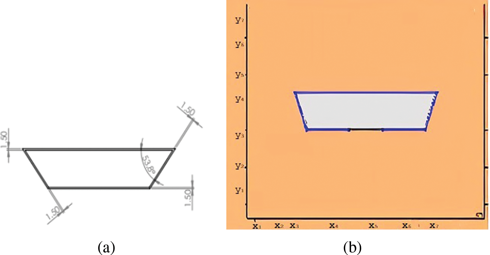
Figure 1: (a) The geometrical designs (b) The comsol geometry
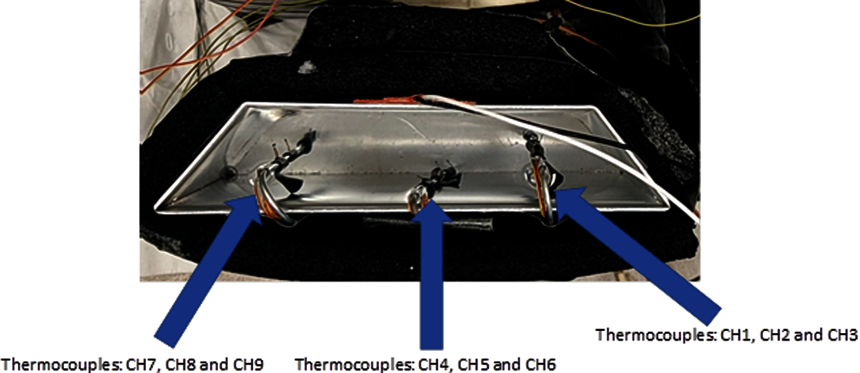
Figure 2: The experimental configuration
The physical properties of PCM are temperature dependent. The volume fraction resulting from phase change and viscous dissipation are negligible. Both the conduction and convection heat transformation take place. The governing equations, by following [36] are:
Continuity equation
Momentum equation
Energy equation
The latent heat content signified by the L in the terms of latent heat (LH) of PCM is:
Here
The Eqs. (3) and (4) provide iterative solution for temperature.
The mushy region is treated as porous medium for enthalpy-porosity technique.
Porosity is zero for fully solidified region; hence zero velocity is resulted in these regions.
4 Properties of Nano Particles
The doping of paraffin wax with Cobalt oxide
The latent heat, heat capacity and density of nano PCM are identified as [37]:
The volume fraction of nano particles is
The viscosity and thermal conductivity of nano PCM are:
Physical Properties of cobalt oxide (
Density 6.11 g/cm3
Melting Point 895
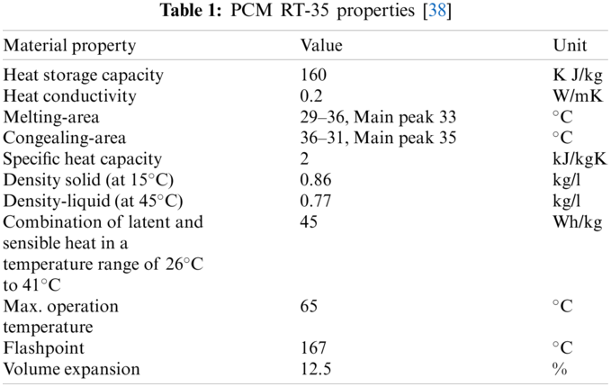
5 Properties of Paraffin RT 35 (PCM)
The industrial PCM utilized in the investigation was paraffin RT-35, with a phase modifying temperature of about 35
Observations for melting of PCM are made after various time intervals. Representative outcomes are described below to understand the conduction convection role for phase change of RT-35 at uniform temperature. The Figs. 3a–3d illustrate the initial melting behavior of the pure PCM after 325 (s). The photograph of the upper observation of the experimental set up in Fig. 3a indicates the starting of melting at the hot bottom side. The melting pattern is more vivid in the colored view from simulation for the same time period as depicted in Fig. 3b. The Fig. 3c delineates the limit of solid PCM and Fig. 3d presents the melting contour. The initial time for melt start is surely lengthy because of low thermal conductivity. After that Figs. 4a–4d to 5a–5d exhibit successive phase transformation of PCM from solid to liquid state after the time intervals 750 (s) and 1500 (s). The melting is slowly increasing whereas the conduction dominates. The photographs are captured after 2500 (s), 3000 (s) and 3750 (s) and exhibited respectively in Figs. 5a–5d, 6a–6d and 7a–7d. In these snaps, the melt processes seems faster and most of the PCM is transformed in to liquid state. Here the convection has developed to join in hand with conduction. Thus the melting seems faster as time passes. Finally, Figs. 8a–8d portray the total melt after 4500 (s). It is to explain that in the beginning, the melting started due to heat conduction which was stronger at the bottom side. The thermal conduction also expanded gradually due to other sides of the trapezium. With the passage of time the thermal convection is identified to play its role and the melting of solid PCM is continued till total melt is yielded after sufficient time length of 4500 (s). It is to mention that the temperature of liquid form of PCM remained almost close to a constant value during this time period and a large amount of heat energy is captured by the PCM mass as latent heat.
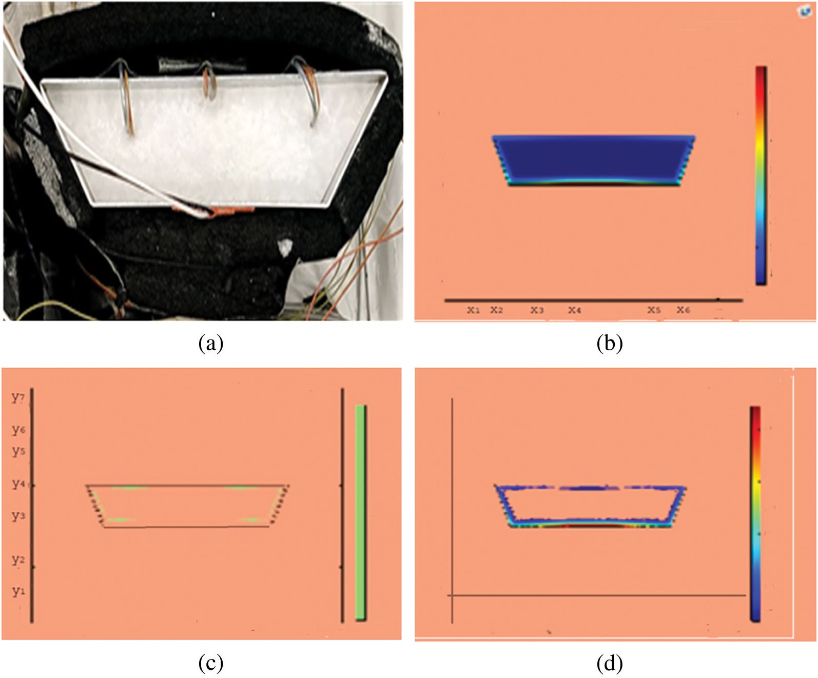
Figure 3: PCM melt-front after 325 (s) (a) lab observation (b) colored view from simulation (c) limit of solid PCM (d) melting contour
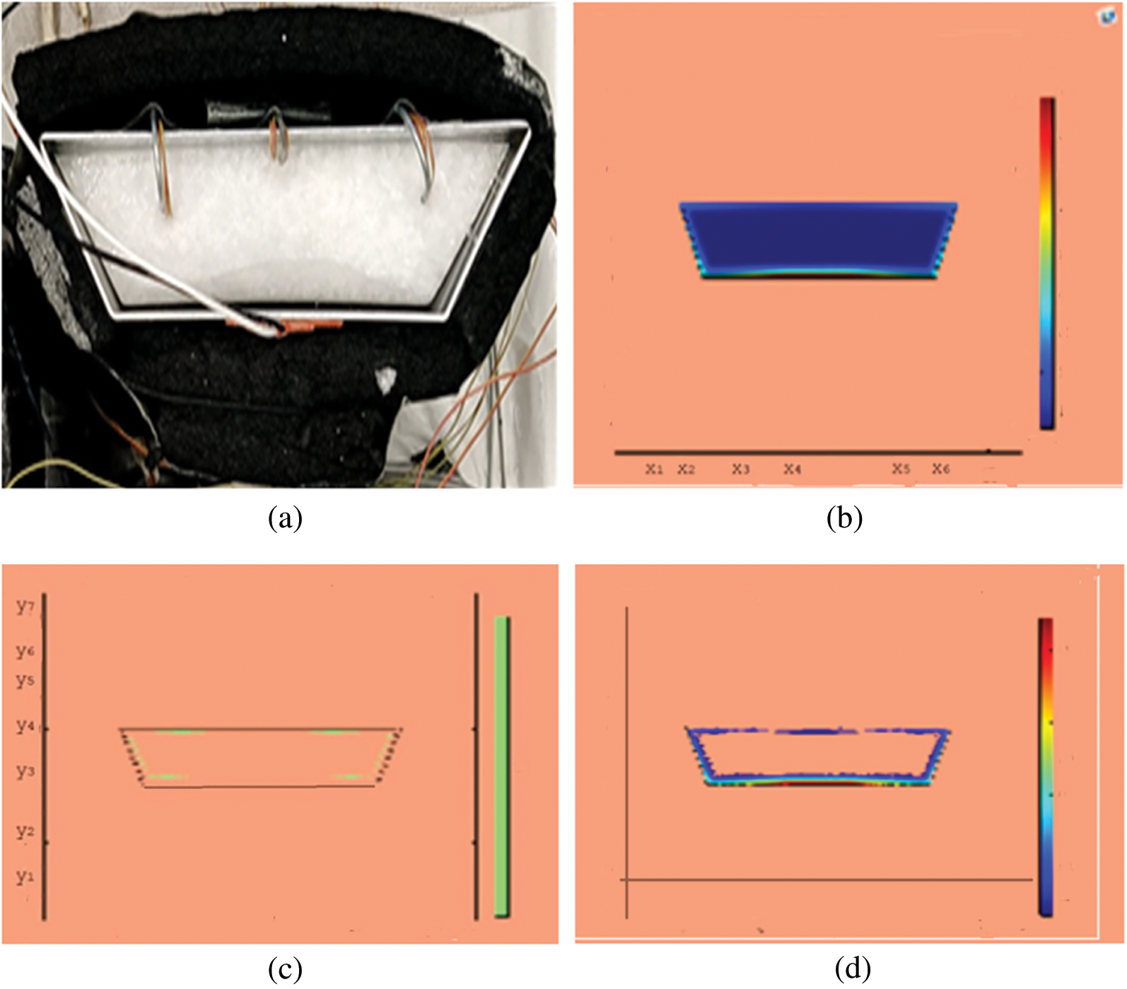
Figure 4: PCM melt-front after 750 (s) (a) lab observation, (b) colored view from simulation (c) limit of solid PCM (d) melting contour
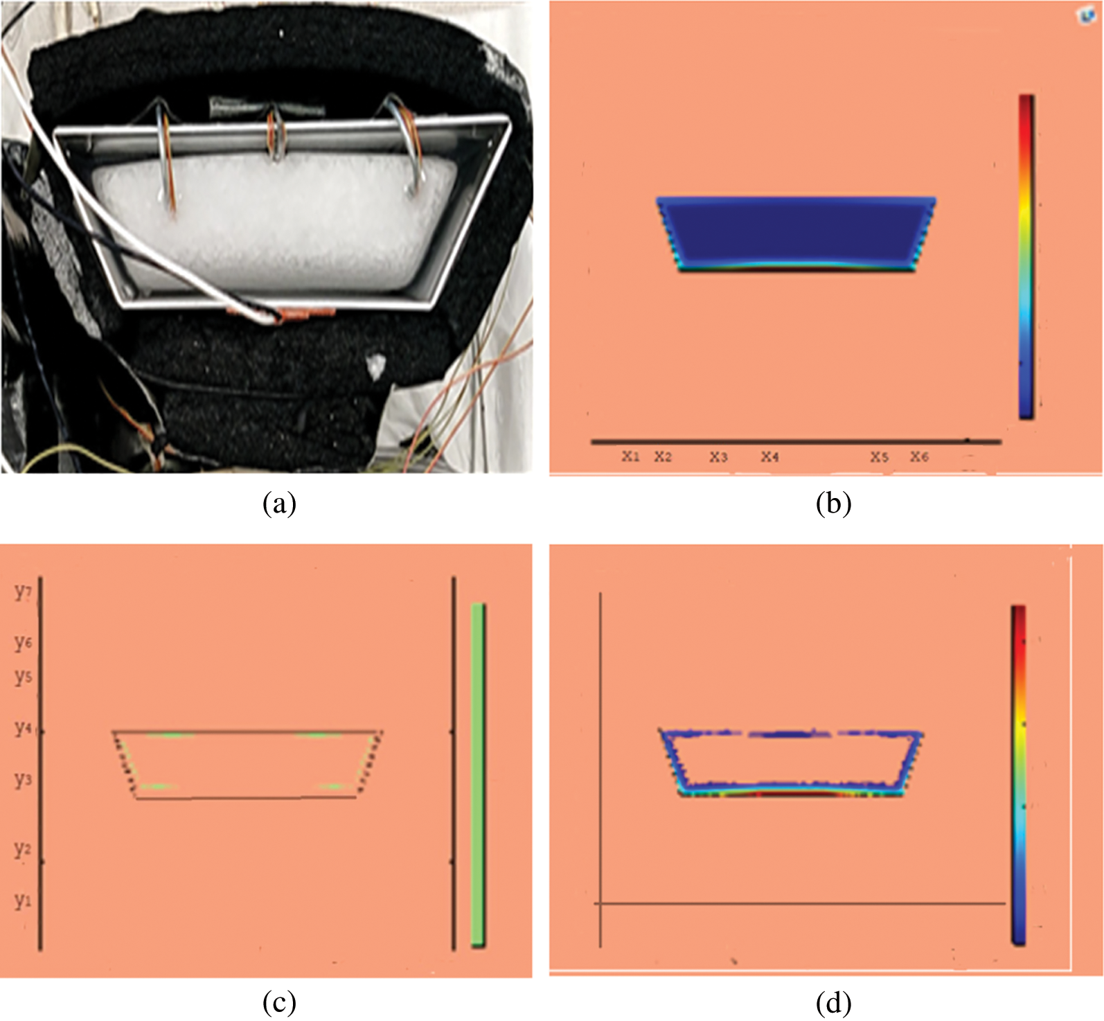
Figure 5: PCM melt-front after 1500 (s) (a) lab observation, (b) colored view from simulation (c) limit of solid PCM (d) melting contour
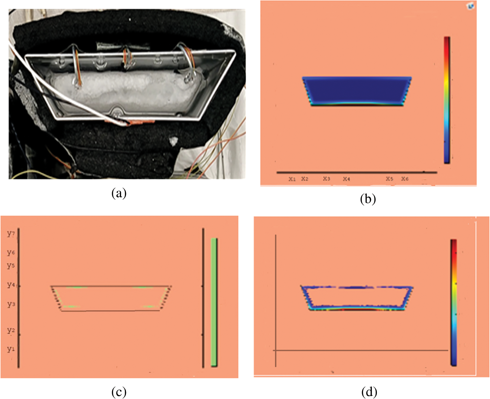
Figure 6: PCM melt-front after 2500 (s) (a) lab observation, (b) colored view from simulation (c) limit of solid PCM (d) melting contour
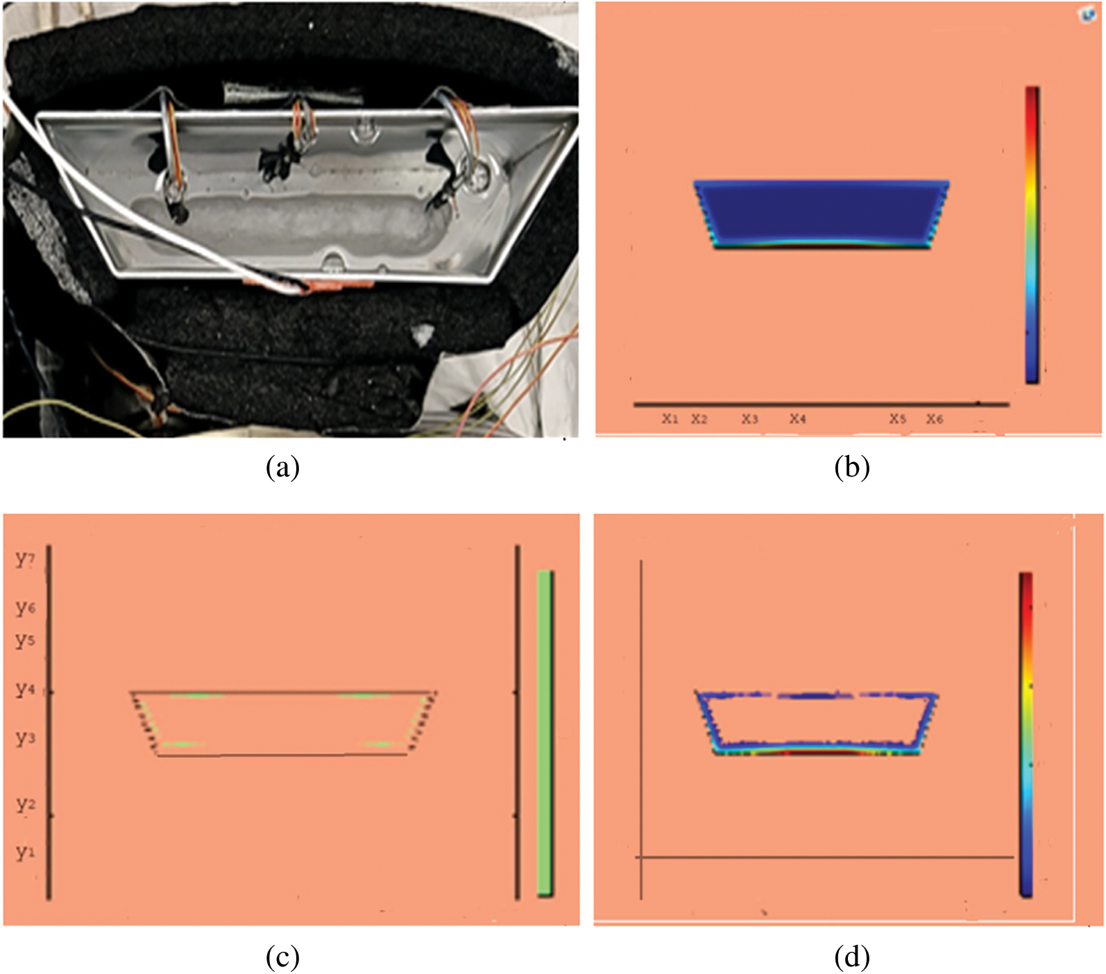
Figure 7: PCM melt-front after 3750 (s) (a) lab observation, (b) colored view from simulation (c) limit of solid PCM (d) melting contour
However, the long time for total melt signifies the low thermal conductivity of PCM as remarked in [23]. Enhancement in thermal conductivity of PCM can be attained by harnessing Comsol environment with mixing of nano entities of cobalt oxide
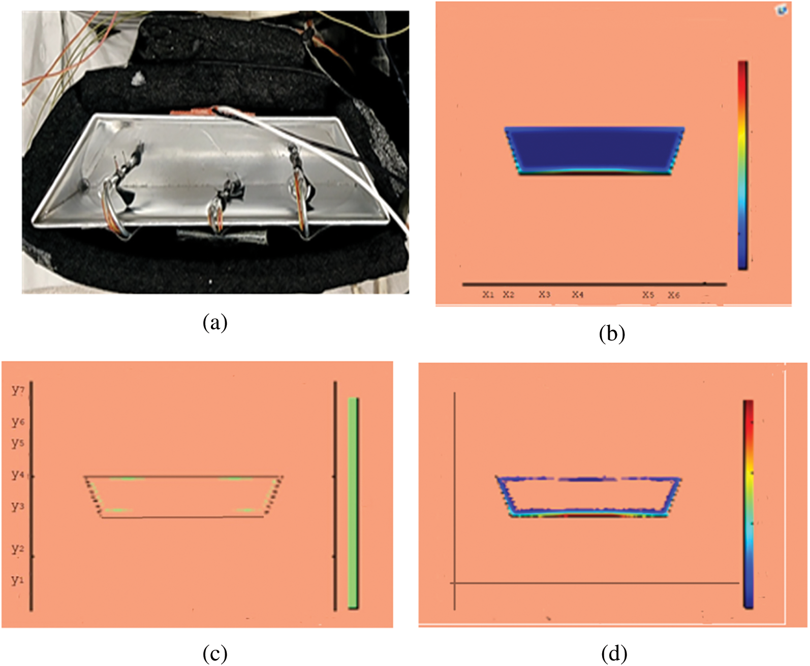
Figure 8: PCM melt-front after 4500 (s) (a) lab observation, (b) colored view from simulation (c) limit of solid PCM (d) melting contour
This section presents snapshots and computational graphical patterns for phase transformation of the bounded PCM for various time lapses as explained in Section 6 above. Each of the Figs. 1–8, from initiation of melting to total melt of pure PCM consists of four sketches where Part (a) depicts photograph of lab experiment, Part (b) pertains to Comsol simulation, Part (c) exhibit limit of remaining solid PCM and Part (d) delineates melting contour. In Figs. 9–12, the fast melting output of the PCM mixed with nanomaterial for various time periods is exhibited in Part (a)’s for solid fraction and in Part (b)’s for simulated outcome of melt front.
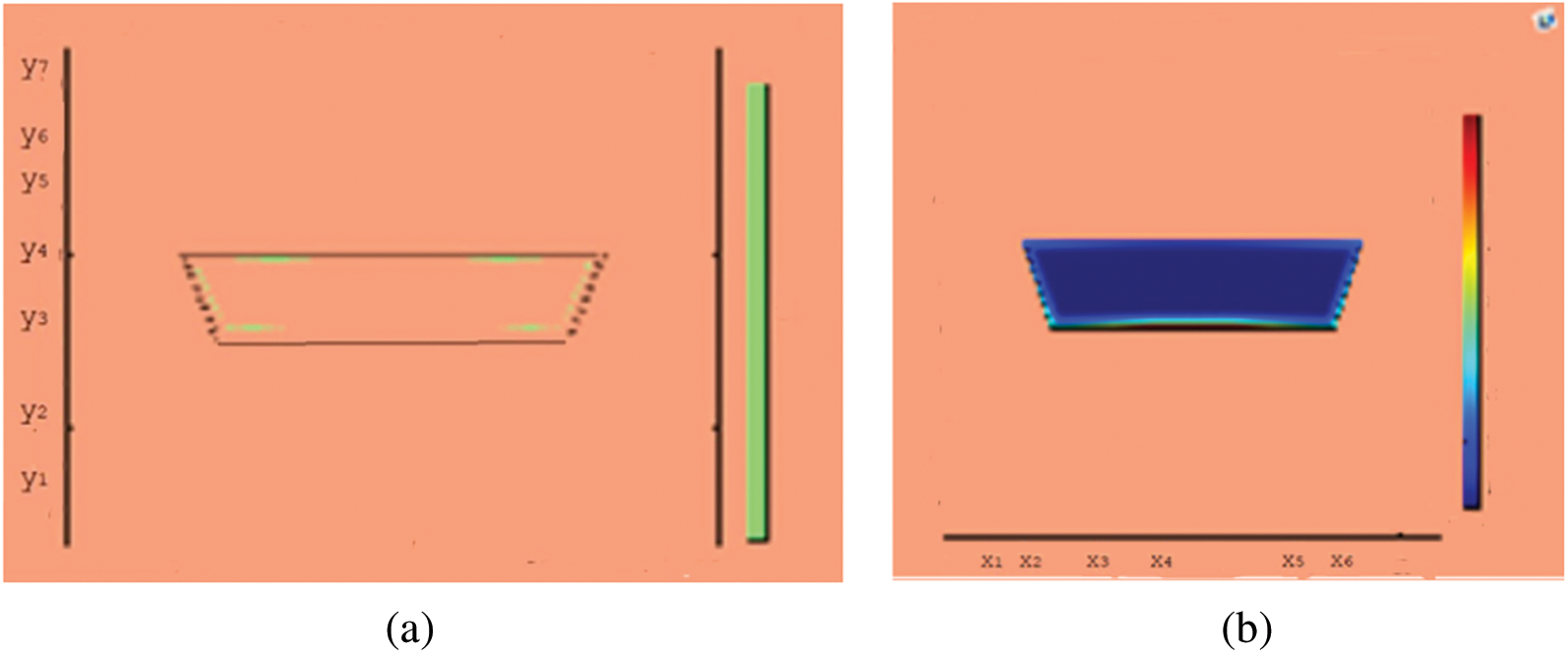
Figure 9: Melting of wax with nano particles after 150 (s) (a) limit of solid PCM (b) colored view from simulation
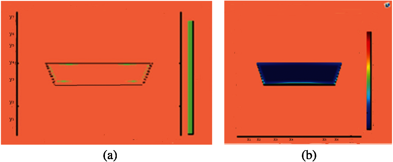
Figure 10: Melting of wax with nano particles after 750 (s) (a) limit of solid PCM (b) colored view from simulation
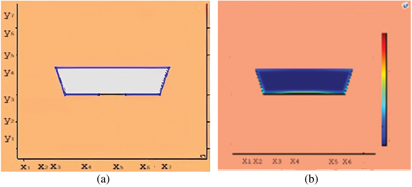
Figure 11: Melting of wax with nano particles after 1500 (s) (a) limit of solid PCM (b) colored view from simulation
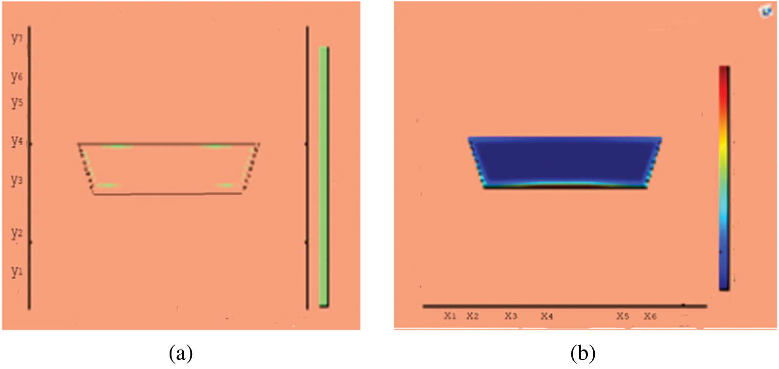
Figure 12: Melting of wax with nano particles after 3000 (s) (a) limit of solid PCM (b) colored view from simulation
A thermal energy storage device in trapezoidal shape is studied by using RT-35 as phase change material (PCM). Three different cases for thermal conductivity are considered for PCM only and PCM with nano particles inclusion. The melting of PCM continued over a considerable time length for a close to uniform temperature. However, the charging time for thermal conductivity enhanced case is notably shorter than that for the pure PCM case. The time duration for total melt front in case of PCM is noted to be 4500 (s) and it is 3000 (s) for the case of nano entity mix. There seemed a 33% less time length for phase transform from solid to liquids form when nano particles are mixed in PCM. In the meanwhile, sufficient amount of heat energy is captured as latent heat. The potential use of PCMs as latent storage media covers renewable energy as well as temperature control of electronic devices and buildings. There is serious short coming in this research field to avail efficient PCMs and effective characteristics of LHS. The extension to this study will address fin augmentation and nano inclusion of PCM melting. Further solidification cycles can be managed and forced convection for a range of Nusselt number will contribute to desired thermal transportation.
Funding Statement: The authors received no specific funding for this study.
Conflicts of Interest: The authors declare that they have no conflicts of interest to report regarding the present study.
1. Kenisarin, M., Mahkamov, K. (2007). Solar energy storage using phase change materials. Renewable and Sustainable Energy Reviews, 11, 1913–1965. DOI 10.1016/j.rser.2006.05.005. [Google Scholar] [CrossRef]
2. Zheng, L., Zhang, W., Liang, F., Lin, S., Jin, X. Y. (2017). Experimental studies of phase change and microencapsulated phase change materials in a cold storage/transportation system with solar driven cooling cycle. Energies, 10, 1867. DOI 10.3390/en10111867. [Google Scholar] [CrossRef]
3. Childs, K., Stovall, T. (2012). Use of phase change material in a building wall assembly: A case study of technical potential in two climates. Second International High Performance Buildings Conference, http://docs.lib.purdue.edu/ihpbc/58. [Google Scholar]
4. Pielichowska, K., Pielichowski, K. (2014). Phase change materials for thermal energy storage. Progress in Materials Science, 65, 67–123. DOI 10.1016/j.pmatsci.2014.03.005. [Google Scholar] [CrossRef]
5. Sharma, A., Tyagi, V. V., Chen, C. R., Buddhi, D. (2009). Review on thermal energy storage with phase change materials and applications. Renewable and Sustainable Energy Reviews, 13(2), 318–345. DOI 10.1016/j.rser.2007.10.005. [Google Scholar] [CrossRef]
6. Bayón, R. (2021). Advanced phase change materials for thermal storage. Applied Science, 11, 1390. DOI 10.3390/app11041390. [Google Scholar] [CrossRef]
7. Mao, Q., Liu, N., Peng, L. (2019). Numerical investigations on charging/discharging performance of a novel truncated cone thermal energy storage tank on a concentrated solar power system. International Journal of Photo Energy, 2019, 17. DOI 10.1155/2019/1609234. [Google Scholar] [CrossRef]
8. Ramakrishnan, S. (2015). A novel paraffin/expanded perlite composite phase change material for prevention of PCM leakage in cementitious composites. Applied Energy, 157, 85–94. DOI 10.1016/j.apenergy.2015.08.019. [Google Scholar] [CrossRef]
9. Basit, R., Li, X., Huang, Z., Zhou, Q. (2020). Heat transfer studies of arrays of prolate particles in gas-solid flows. Mathematical Problems in Engineering, 2020, 12. DOI 10.1155/2020/6639172. [Google Scholar] [CrossRef]
10. Ferrer, G. (2017). New proposed methodology for specific heat capacity determination of materials for thermal energy storage (TES) by DSC. Journal of Energy Storage, 11, 1–6. [Google Scholar]
11. Wu, Y., Tang, Y., Li, Z., Ding, X., Yuan, W. et al. (2016). Experimental investigation of a PCM-HP heat sink on its thermal performance and anti-thermal-shock capacity for high-power LEDs. Applied Thermal Engineering, 108, 192–203. DOI 10.1016/j.applthermaleng.2016.07.127. [Google Scholar] [CrossRef]
12. Zsembinszki, G., Fernández, A. G., Cabeza, L. F. (2020). Selection of the appropriate phase change material for two innovative compact energy storage systems in residential buildings. Applied Sciences, 10, 2116. DOI 10.3390/app10062116. [Google Scholar] [CrossRef]
13. Avci, M., Yazici, M. Y. (2013). Experimental study of thermal energy storage characteristics of a paraffin in a horizontal tube-in-shell storage unit. Energy Conversion and Management, 73, 271–277. DOI 10.1016/j.enconman.2013.04.030. [Google Scholar] [CrossRef]
14. Delgado-Diaz, W., Stamatiou, A., Maranda, S., Waser, R., Worlitschek, J. (2020). Comparison of heat transfer enhancement techniques in latent heat storage. Applied Sciences, 10, 5519. DOI 10.3390/app10165519. [Google Scholar] [CrossRef]
15. Li, S. W., Chen, Y., Sun, Z. Q. (2017). Numerical simulation and optimization of melting process of phase change material inside horizontal annulus. Energies, 10, 1249. DOI 10.3390/en10091249. [Google Scholar] [CrossRef]
16. Farid, M. M., Khudhair, A. M., Razack, S. A. K., Al-Hallaj, S. (2004). A review on phase change energy storage: Materials and applications. Energy Conversion and Management, 45, 1597–1615. DOI 10.1016/j.enconman.2003.09.015. [Google Scholar] [CrossRef]
17. Zhang, Y., Faghr, A. (1996). Heat transfer enhancement in latent heat thermal energy storage system by using the internally finned tube. Heat Mass Transfer, 39, 3165–3173. DOI 10.1016/0017-9310(95)00402-5. [Google Scholar] [CrossRef]
18. Sharikian, V., Ziskind, G., Letan, R. (2005). Numerical investigation of a PCM-based heat sink with internal fins. Heat Mass Transfer, 48, 3689–3706. DOI 10.1016/j.ijheatmasstransfer.2004.10.042. [Google Scholar] [CrossRef]
19. Mat, S., Al-Abidi, A. A., Sopian, K., Sularman, M. Y., Mohammad, A. T. (2013). Enhance heat transfer for PCM melting in triplex tube with internal–external fins. Energy Conversion and Management, 74, 223–236. DOI 10.1016/j.enconman.2013.05.003. [Google Scholar] [CrossRef]
20. Zhu, F., Zhang, C., Gong, X. (2017). Numerical analysis on the energy storage efficiency of phase change material embedded in finned metal foam with graded porosity. Applied Thermal Engineering, 123, 256–265. DOI 10.1016/j.applthermaleng.2017.05.075. [Google Scholar] [CrossRef]
21. Yang, X., Lu, Z., Bai, Q., Zhang, Q., Jin, L. et al. (2017). Thermal performance of a shell-and-tube latent heat thermal energy storage unit: Role of annular fins. Applied Energy, 202, 558–570. [Google Scholar]
22. Bechiri, M., Mansouri, K. (2016). Analytical study of heat generation effects on melting and solidification of nano-enhanced PCM inside a horizontal cylindrical enclosure. Applied Thermal Engineering, 104, 779–790. DOI 10.1016/j.apenergy.2017.05.007. [Google Scholar] [CrossRef]
23. Dhaidan, N. S., Khodadadi, J. M., Al-Hattab, T. A., Al-Mashat, S. M. (2013). Experimental and numerical investigation of melting of phase change material/nanoparticle suspensions in a square container subjected to a constant heat flux. International Journal of Heat and Mass Transfer, 66, 672–683. DOI 10.1016/J.APPLTHERMALENG.2016.05.105. [Google Scholar] [CrossRef]
24. Atal, A., Wang, Y., Harsha, M., Sengupta, S. (2016). Effect of porosity of conducting matrix on a phase change energy storage device. International Journal of Heat and Mass Transfer, 93, 9–16. DOI 10.1016/j.ijheatmasstransfer.2015.09.033. [Google Scholar] [CrossRef]
25. Murshed, S. M. S., Nieto de Castro, C. A. (2017). A critical review of traditional and emerging techniques and fluids for electronics cooling. Renewable and Sustainable Energy Reviews, 78, 821–833. DOI 10.1016/j.rser.2017.04.112. [Google Scholar] [CrossRef]
26. Afif, H. K. (2012). Solar energy storage in buildings using composite PCM containing nano particles (Master Thesis). University of Jordan, Jordan. [Google Scholar]
27. He, Q., Wang, S., Tong, M., Liu, Y. (2012). Experimental study on thermophysical properties of nanofluids as phase-change material in low temperature storage. Energy Conversion and Management, 64, 199–205. DOI 10.1088/1757-899X/912/4/042040. [Google Scholar] [CrossRef]
28. Chaichan, M. T., Kamel, H., Shaima, A. N., Al-Ajeely, M. (2015). Thermal conductivity enhancement by using nano-material in phase change material for latent heat thermal energy storage systems. Saussurea, 5(6), 48–55. [Google Scholar]
29. Belessiotis, G. V., Papadokostaki, K. G., Favvas, E. P., Efthimiadou, E. K., Karellas, S. (2018). Preparation and investigation of distinct and shape stable paraffin/SiO2 composite PCM nano spheres. Energy Conversion and Management, 168, 382–394. DOI 10.1016/j.enconman.2018.04.059. [Google Scholar] [CrossRef]
30. Parsazadeh, M., Duan, X. (2017). Numerical and statistical study on melting of nanoparticle enhanced phase change material in a shell-and-tube thermal energy storage system. Applied Thermal Engineering, 111, 950–960. DOI 10.1016/j.apenergy.2018.02.052. [Google Scholar] [CrossRef]
31. Fawziea, M. H., Faraj, J. J., Kareem, R. J. (2018). Experimental investigation of adding nano-particles to PCM for heating applications. Journal of Mechanical Engineering and Automation, 8(1), 32–37. DOI 10.5923/j.jmea.20180801.03. [Google Scholar] [CrossRef]
32. Motahar, S., Alemrajabi, A. A., Khodabandeh, R. (2017). Experimental study on solidification process of a phase change material containing TiO2 nanoparticles for thermal energy storage. Energy Conversion and Management, 138, 162–170. DOI 10.1016/j.enconman.2017.01.051. [Google Scholar] [CrossRef]
33. Sharma, L. M., Changb, W., Tahir, A. A., Reddy, K. S., Mallick, T. K. (2017). Nano-enhanced phase change material for thermal management of BICPVS. Applied Energy, 208, 719–733. DOI 10.1016/j.apenergy.2017.09.076. [Google Scholar] [CrossRef]
34. Yazici, M. Y., Saglam, M., Aydin, O., Avci, M. (2021). Thermal energy storage performance of PCM/graphite matrix composite in a tube-in-shell geometry. Thermal Science and Engineering Progress, 23, 100915. DOI 10.1016/j.tsep.2021.100915. [Google Scholar] [CrossRef]
35. Rubitherm Technologies, GmbH, Imhoffweg 6 D-12307. Berlin, Version: 06.08.2018. https://www.rubitherm.com. [Google Scholar]
36. Li, S., Chen, Y., Sun, Z. (2017). Numerical simulation and optimization of the melting process of phase change material inside horizontal annulus. Energies, 10, 1249. DOI 10.3390/en10091249. [Google Scholar] [CrossRef]
37. Auriemma, M., Iazzetta, A. (2016). Numerical analysis of melting of paraffin wax with Al2O3, ZnO and CuO nano particles in rectangular enclosure. Indian Journal of Science and Technology, 9(3), 1–8. DOI 10.17485/ijst/2016/v9i4/72601. [Google Scholar] [CrossRef]
38. Liu, H., Li, S., Chen, Y., Sun, Z. (2014). The melting of phase change material in a cylinder shell with hierarchical heat sink array. Applied Thermal Engineering, 73, 975–983. DOI 10.1016/j.applthermaleng.2014.08.062. [Google Scholar] [CrossRef]
 | This work is licensed under a Creative Commons Attribution 4.0 International License, which permits unrestricted use, distribution, and reproduction in any medium, provided the original work is properly cited. |