| Computer Modeling in Engineering & Sciences |
DOI: 10.32604/cmes.2022.017630
ARTICLE
Topology Optimization with Aperiodic Load Fatigue Constraints Based on Bidirectional Evolutionary Structural Optimization
1Heavy-Duty Intelligent Manufacturing Equipment Innovation Center of Hebei Province, School of Mechanical Engineering, Yanshan University, Qinhuangdao, China
2Space Star Technology Co., Ltd., Beijing, China
*Corresponding Author: Tao Chang. Email: changtao20210901@163.com
Received: 25 May 2021; Accepted: 03 August 2021
Abstract: Because of descriptive nonlinearity and computational inefficiency, topology optimization with fatigue life under aperiodic loads has developed slowly. A fatigue constraint topology optimization method based on bidirectional evolutionary structural optimization (BESO) under an aperiodic load is proposed in this paper. In view of the severe nonlinearity of fatigue damage with respect to design variables, effective stress cycles are extracted through transient dynamic analysis. Based on the Miner cumulative damage theory and life requirements, a fatigue constraint is first quantified and then transformed into a stress problem. Then, a normalized termination criterion is proposed by approximate maximum stress measured by global stress using a P-norm aggregation function. Finally, optimization examples show that the proposed algorithm can not only meet the requirements of fatigue life but also obtain a reasonable configuration.
Keywords: Topology optimization; bidirectional evolutionary structural optimization; aperiodic load; fatigue life; stress constraint
For air vehicles, components or supports are exposed to aperiodic loads, and there are strict requirements for minimum service life. The weight of aircraft parts directly affects carrying travel, and lightweight research can greatly improve the power-to-weight capacity. Therefore, this paper studies the topology optimization problem with fatigue life as the constraint and the minimum volume/weight as the objective under aperiodic loading.
The field of topology optimization mainly focuses on minimizing structural compliance [1–3] to increase structural stiffness. At present, there are roughly three ways to solve topology optimization with fatigue constraints. First, fatigue life is directly used as an optimal parameter, which is usually realized by a heuristic algorithm because fatigue life is not differentiable from variables. For example, Haiba et al. [4] used the ESO method in 2005 to establish an element deletion criterion based on fatigue life to gradually remove high-life elements. In the second way, fatigue cumulative damage is set as the design parameter instead of fatigue life. Jacob et al. [5] used fatigue cumulative damage in 2016 to describe the fatigue response and P-norm aggregation function to agglomerate fatigue constraints on the variable density method. In 2018, Seung et al. [6] developed topology optimization of fatigue constraints under variable amplitude cyclic loads based on the equivalent static load method. In 2020, Chen et al. [7] penalized cumulative damage to achieve anti-fatigue topology optimization. However, cumulative damage is highly nonlinear with stress, which seriously affects optimization stability. In the third way, fatigue is equivalent to stress using the fatigue failure criterion. In 2014, Holmberg et al. [8] developed a variable density method taking critical fatigue stress and static stress as constraint conditions simultaneously. In 2015, Jeong et al. [9] proposed a topology optimization method considering dynamic fatigue and static failure criteria using average stress to represent fatigue based on the variable density method. In 2019, Nabaki et al. [10] used a modified Goodman failure criterion to study the maximum stiffness problem under volume and fatigue life constraints. In 2020, Zhao et al. [11] discussed topology optimization under a high cycle fatigue constraint based on the Crossland criterion, and the fatigue constraint was equivalent to the peak stress not exceeding the threshold.
However, the aperiodicity and randomness of the aperiodic load determine that its fatigue cannot be described by stress or strain directly and can only be counted by the rain-flow method and expressed by fatigue damage. Due to the nonlinearity of fatigue damage with life history, there are few studies concerning topology optimization under aperiodic load fatigue constraints. This research aims to address the high cycle fatigue problem under aperiodic loading. If the stress value can be connected with fatigue damage [8], the fatigue constraint can be transformed to a critical stress problem.
Stress constraint topology optimization has conundrums of locality. The stress of each element must be constrained to search for the maximum stress. The sensitivity of each constraint needs to be calculated, so it leads to excessive computation whether using a direct method or adjoint method. To solve this problem, aggregation functions, such as the P-norm method [12] and K-S function method [13], can be applied. In 2013, Luo et al. [14] proposed an enhanced K-S function based on the variable density method to solve topological optimization for minimizing volume under stress constraints. In 2019, Fan et al. [15] addressed minimizing compliance under volume and stress constraints based on the BESO method and P-norm equation. In 2019, Long et al. [16] studied stress-constrained topological optimization under a simple harmonic load using the P-norm function based on the variable density method. In 2020, Zhao et al. [17] improved BESO with a dynamic stress response under random loads by the P-norm function.
In this paper, aiming at the severe nonlinearity of cumulative damage under aperiodic loading, a transformational relation of fatigue damage with stress is established. First, fatigue damage of the substep is calculated by the stress time history, and the problem is transformed into a stress topology optimization problem based on BESO. In the classic BESO method, volume is generally the constraint, so volume evolution is adopted to realize element addition and deletion, and the objective change value is taken as the convergence criterion. However, volume is the objective here, and if volume is taken to measure evolution and convergence simultaneously, it will be difficult to converge due to missing stress. Therefore, a normalized parameter, which comprehensively considers volume and stress, is proposed and taken as the convergence parameter. In this way, the topology lightening problem with a high cycle fatigue life as a constraint is solved.
2 Fatigue Constraint Treatment
2.1 Fatigue Life Calculation under Aperiodic Load
To interpret the relationship between fatigue life, damage and stress, this section briefly introduces a fatigue analysis program for aperiodic loads. The general process is as follows: first, fatigue life is calculated by alternating stress and average stress extracted from the transient stress time history. To explain the multiaxial stress of each node, the signed von Mises stress is calculated. The reversal of symbolic von Mises stress and average stress are determined by rain flow counting. The Goodman correction method is used to calculate the amplitude of the effective stress. Then, the Basquin equation is applied to calculate the number of failure cycles for each effective stress amplitude. Finally, all the damage caused by stress reversal in the loading history is accumulated linearly by the Palmgren–Miner law [18].
In detail, the stress history is solved by a given dynamic system as
where
where
where
Equivalent parameters similar to von Mises stress are usually positive [19], so a negative sign of von Mises stress is determined by a positive or negative sign of the first invariant. The time history of alternating stress is obtained as
where
To consider the influence of the average stress, the Goodman correction equation is used to calculate the amplitude of the effective stress
where
The number of failure cycles (Ni) of each effective stress amplitude can be computed by the Basquin equation. Thus,
where
Cumulative fatigue damage can be calculated by the Palmgren–Miner law as
where l is load series and
Therefore, fatigue damage is expressed by the stress amplitude as
From Eq. (11), there is an exponential relationship between fatigue damage and stress, and it is nonlinear. Therefore, it is not conducive to setting fatigue damage as a constraint condition.
2.2 Fatigue to Stress Constraint
In this section, the process course of converting the fatigue lifetime requirement to a stress constraint is presented. First, the position of the danger point is obtained by transient dynamic analysis loading aperiodic cyclic force. In addition, the stress time history is obtained. Then, the rain flow counting method is used to extract the effective stress cycle. Fatigue damage is calculated with the Palmgren–Miner criterion. Finally, according to the lifetime requirements, the critical stress level is inversely calculated and taken as the constraint condition for topology optimization. The specific implementation steps are as follows:
(1) With the requirements of fatigue design life, stress amplitude
(2) Assuming that k damage calculations are made, based on the Miner theory, the total damage can be obtained as
(3) If
(4)
(5)
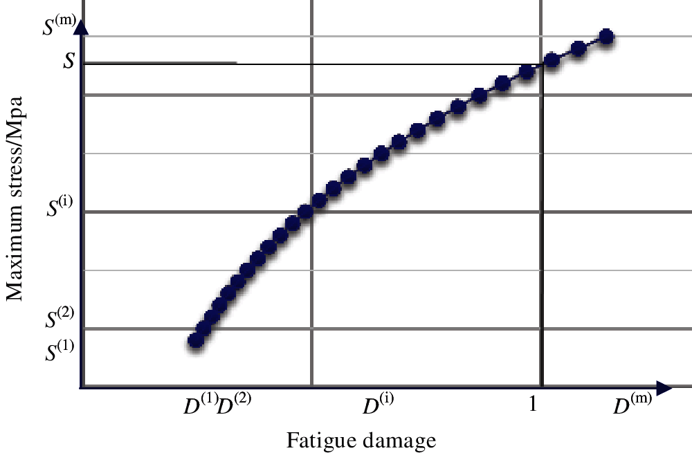
Figure 1: Stress damage curve
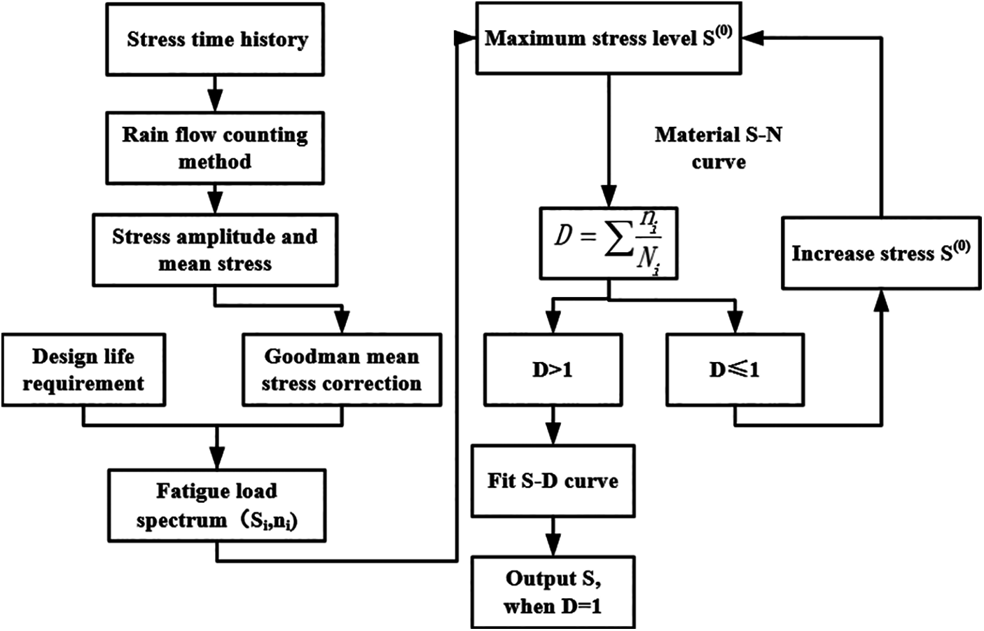
Figure 2: Flow chart of transforming fatigue constraint to stress constraint
3 Fatigue Constrained Topology Optimization on BESO
Through the conversion above, fatigue-constrained topology optimization can be transformed into a stress-constrained problem. To reduce the quantity of stress constraints at every cycle, the P-norm aggregation function is used as
where
where xi and Vi represent the i-th element variable and the i-th element volume respectively.
Classic BESO uses the change of objective function as the convergence criterion. The objective parameter of optimization model in this paper is volume. If the volume change is set as the convergence criterion, the volume increment between adjacent iterations will alter drastically, and the convergence value is hard to realize. To take into account both optimization objective and constraint parameters, this paper proposes a normalized performance index PI, which can comprehensively consider stress change and volume change as
where
In general, M refers to the range of iteration intervals that determines convergence, usually 3–10, which means that the performance change over the past 10 iterations is small enough to achieve convergence when it is less than τ. τ is the convergence error.
Except for sensitivity analysis, convergence criterion and fatigue constraint, the rest of the flow is based on BESO theory [20]. A flow chart of the optimization algorithm with fatigue constraints is shown in Fig. 3.
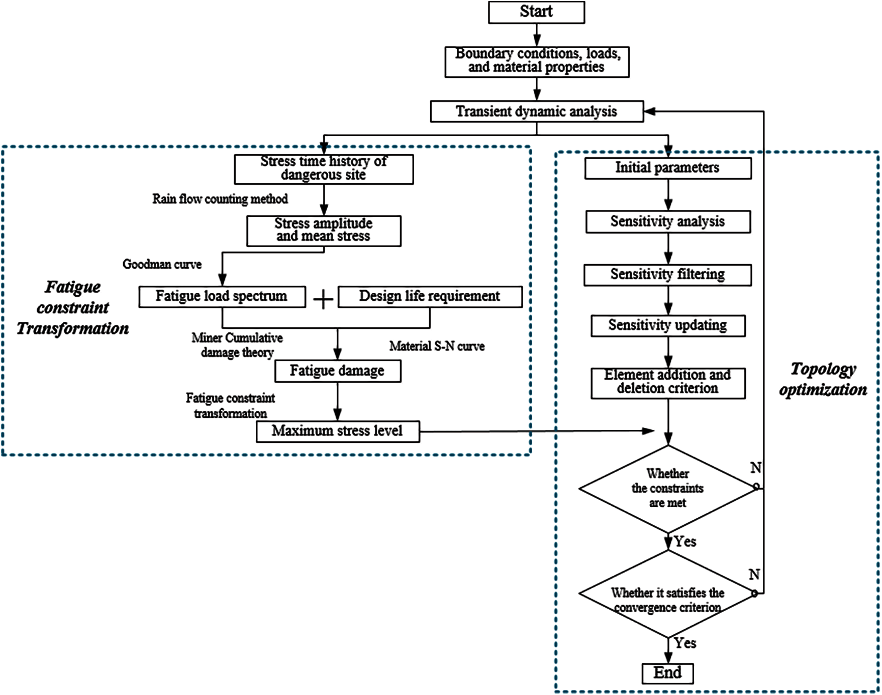
Figure 3: Flow chart of optimization algorithm with fatigue constraints
To show the effectiveness and correctness of the proposed method, we design two numerical examples: double-bar plates and L-shaped beams. Therefore, a double-bar plate is designed with no obvious stress concentration, and an L-shaped beam is designed with stress concentration. The fatigue life is designed to be 140 h to confine to elastic deformation. The stress aggregation norm in Eq. (12) is set at p = 6.
The initial design area and boundary conditions of the double-bar plate are shown in Fig. 4. The thickness is 1 mm. The structure is divided into 80 × 40 quadrilateral plane stress elements. A fixed constraint is applied on the lower side, and an aperiodic load is applied to the 11th node in the middle of the upper side. The time history of the aperiodic load is shown in Fig. 5. Young's modulus, Poisson's ratio and the material density are set as E = 71 GPa, v = 0.33 and ρ = 2793 Kg/m³. Material S-N curve equation expresses as

Figure 4: Initial design area of double-bar structure
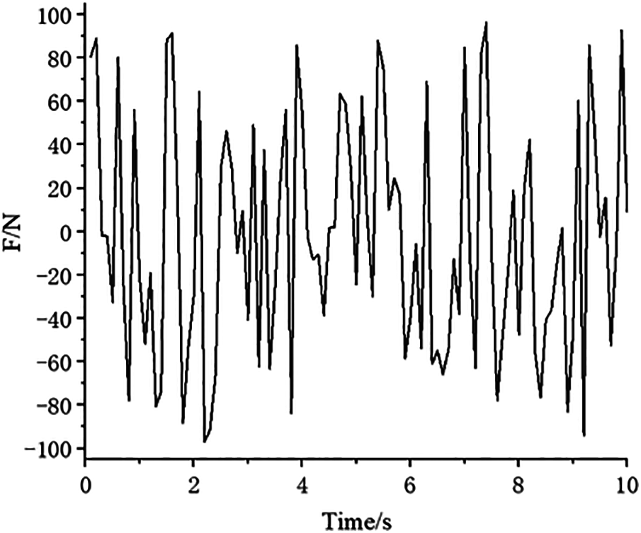
Figure 5: Load time history
There is no stress concentration caused by the structure shape in the double-bar model. The iterative changes in the volume fraction and PI are shown in Fig. 6. After 100 iterations, the volume fraction and PI reach a platform, and the convergence criterion is met. When PI reaches approximately 3.36, it tends to converge, and the objective function is 0.23. Relatively, the maximum stress and P-norm aggregation stress show slight fluctuations during the last 20 iteration cycles, as shown in Fig. 7. The maximum stress value exhibits a smaller downward trend than the P-norm aggregation stress and an upward trend. This shows that the P-norm aggregation function helps local stress reach convergence. Fig. 8 shows the final optimal configuration and stress distribution result. Direction inclination leads to loading asymmetry between the left and right parts, resulting in the asymmetric configuration, as shown in Fig. 8a.
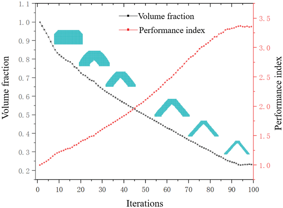
Figure 6: Variation curve of objective volume and PI
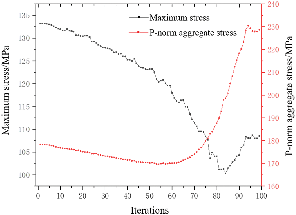
Figure 7: Variation curve of structural maximum stress and P-norm aggregation stress
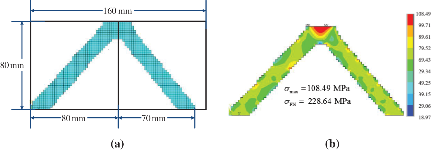
Figure 8: Final iterative results of double-bar plate and stress nephogram (a) Final iterative configuration (b) Stress nephogram
The initial design area and boundary conditions of the L-shaped beam are shown in Fig. 9. The design area is meshed by four-node plane elements with a length of 1 mm. The upper side is fixed, and the aperiodic load is shown in Fig. 10. Force is applied on the top vertex of right boundary. To avoid stress concentration at the loading position, the load is evenly distributed to 8 nodes. The material parameters are exactly the same as those in the double-bar plate.
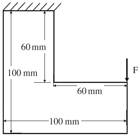
Figure 9: L-shaped beam structure
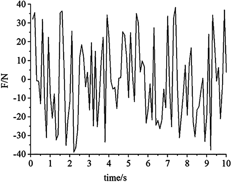
Figure 10: Load time curve
The variation curve of the volume fraction and PI is obtained, as shown in Fig. 11. With iteration progress, the volume and PI fluctuate violently after 30 steps. This is due to the high nonlinearity of stress. With optimization, in some areas with high stress concentrations, the high stress distribution is very sensitive to even minor topological changes. However, the amplitude of oscillation tends to decrease with increasing iteration number. When PI reaches approximately 1.73, it tends to converge, and the objective function is 0.69. Approximately 250 steps are consumed to reach convergence. Since the convergence criterion is a relative change between the last and first range of the iteration interval, iteration convergence occurs since a small floating value is reached. After repeated trial calculations, a better convergence effect is obtained when the range of iteration intervals M = 4 and convergence error τ = 0.0001.
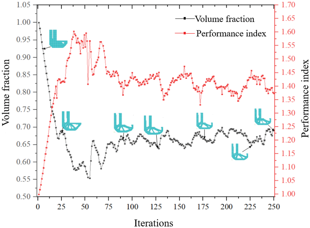
Figure 11: Variation curve of objective function and performance index
Curves of the maximum stress and P-norm aggregation stress are shown in Fig. 12. The final topology and its stress cloud diagram are shown in Fig. 13. The maximum stress is 175.74 MPa, and the P-norm aggregation stress is 228.14.
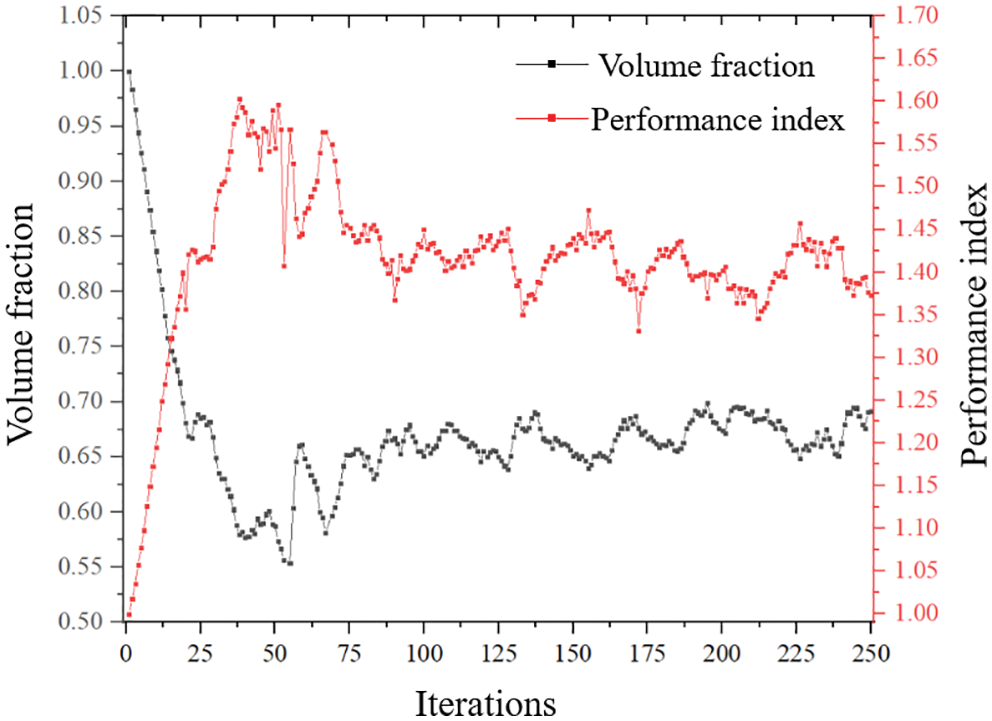
Figure 12: Variation curve of structural maximum stress and P-norm aggregation stress
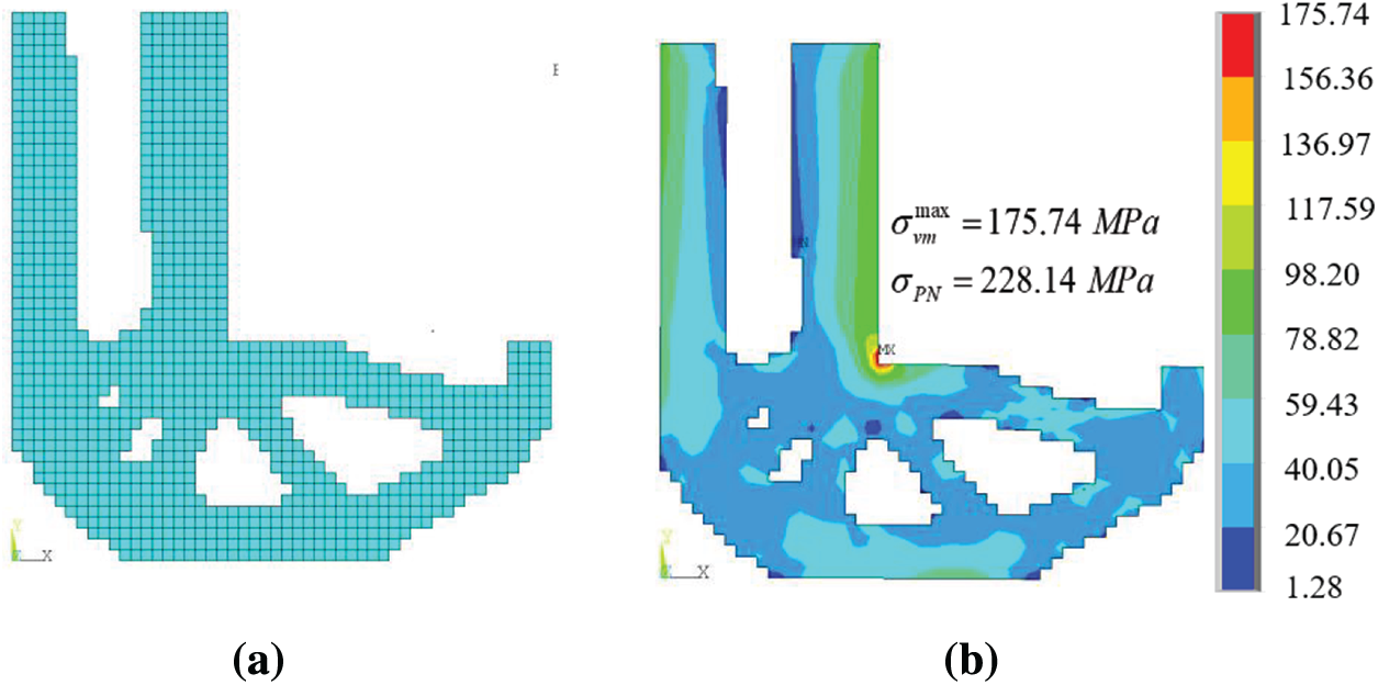
Figure 13: Final iterative result of L-shaped beam and stress nephogram (a) Final iterative shape (b) Stress nephogram
Fatigue life, strength and stiffness are three important factors that designers cannot ignore in engineering. Aiming at high cycle fatigue caused by aperiodic load, this paper realizes topology optimization method of aperiodic load based on BESO.
In order to solve the severe nonlinearity of fatigue damage to design variables, this paper uses fatigue analysis to calculate cumulative damage and then equivalent fatigue damage to critical stress by stress damage curve to transform fatigue constraint problem to stress constraint problem.
Then, P-norm is used for stress aggregation, and the dimensionless index PI is proposed to improve convergence speed. The effectiveness of proposed method in obtaining the lightest configuration which strictly satisfies life constraint is proved by two examples with and without stress concentration.
Funding Statement: This research is funded by Chinese National Natural Science Foundation (No. 51890881). Science and Technology Project of Hebei Education Department (Nos. ZD2020156, QN2018228).
Conflicts of Interest: The authors declare that they have no conflicts of interest to report regarding the present study.
1. Xia, L., Xia, Q., Huang, X., Xie, Y. (2018). Bi-directional evolutionary structural optimization on advanced structures and materials: A comprehensive review. Archives of Computational Methods in Engineering, 25(2), 437–478. DOI 10.1007/s11831-016-9203-2. [Google Scholar] [CrossRef]
2. Gao, J., Xiao, M., Zhang, Y., Gao, J. (2020). A comprehensive review of isogeometric topology optimization: Methods, applications and prospects. Chinese Journal of Mechanical Engineering, 33(1), 87. DOI 10.1186/s10033-020-00503-w. [Google Scholar] [CrossRef]
3. Deaton, J. D., Grandhi, R. V. (2014). A survey of structural and multidisciplinary continuum topology optimization: Post 2000. Structural and Multidisciplinary Optimization, 49(1), 1–38. DOI 10.1007/s00158-013-0956-z. [Google Scholar] [CrossRef]
4. Haiba, M., Barton, D., Brooks, P., Levesley, M. (2005). Evolutionary structural optimisation of dynamically loaded components in consideration of fatigue life. Advances in Engineering Software, 36(1), 49–57. DOI 10.1016/j.advengsoft.2004.03.022. [Google Scholar] [CrossRef]
5. Jacob, O., Erik, L. (2017). Topology optimization with finite-life fatigue constraints. Structural and Multidisciplinary Optimization, 56(5), 1045–1059. DOI 10.1007/s00158-017-1701-9. [Google Scholar] [CrossRef]
6. Seung, H. J., Jong, W. L., Gil, H. Y., Dong, H. C. (2018). Topology optimization considering the fatigue constraint of variable amplitude load based on the equivalent static load approach. Applied Mathematical Modelling, 56, 626–647. DOI 10.1016/j.apm.2017.12.017. [Google Scholar] [CrossRef]
7. Chen, Z., Long, K., Wen, P., Nouman, S. (2020). Fatigue-resistance topology optimization of continuum structure by penalizing the cumulative fatigue damage. Advances in Engineering Software, 150, 102924. DOI 10.1016/j.advengsoft.2020.102924. [Google Scholar] [CrossRef]
8. Holmberg, E., Torstenfelt, B., Klarbring, A. (2014). Fatigue constrained topology optimization. Structural and Multidisciplinary Optimization, 50(2), 207–219. DOI 10.1007/s00158-014-1054-6. [Google Scholar] [CrossRef]
9. Jeong, S. H., Choi, D. H., Yoon, G. H. (2015). Fatigue and static failure considerations using a topology optimization method. Applied Mathematical Modelling, 39(3–4), 1137–1162. DOI 10.1016/j.apm.2014.07.020. [Google Scholar] [CrossRef]
10. Nabaki, K., Shen, J. H., Huang, X. (2019). Evolutionary topology optimization of continuum structures considering fatigue failure. Materials & Design, 166(15), 107586. DOI 10.1016/j.matdes.2019.107586. [Google Scholar] [CrossRef]
11. Zhao, L., Xu, B., Han, Y., Xue, J., Rong, J. (2020). Structural topological optimization with dynamic fatigue constraints subject to dynamic random loads. Engineering Structures, 205, 110089. DOI 10.1016/j.engstruct.2019.110089. [Google Scholar] [CrossRef]
12. Yang, R. J., Chen, C. J. (1996). Stress-based topology optimization. Structural and Multidisciplinary Optimization, 12(2), 98–105. DOI 10.1007/BF01196941. [Google Scholar] [CrossRef]
13. Duysinx, P., Sigmund, O. (1998). New developments in handling stress constraints in optimal material distribution. Proceedings of the 7th AIAA/USAF/NASA/ISSMO Symposium on Multidisciplinary Analysis and Optimization, pp. 98–4906, St. Louis. [Google Scholar]
14. Luo, Y., Wang, M. Y., Kang, Z. (2013). An enhanced aggregation method for topology optimization with local stress constraints. Computer Methods in Applied Mechanics and Engineering, 254, 31–41. DOI 10.1016/j.cma.2012.10.019. [Google Scholar] [CrossRef]
15. Fan, Z., Xia, L., Lai, W., Xia, Q., Shi, T. (2019). Evolutionary topology optimization of continuum structures with stress constraints. Structural and Multidisciplinary Optimization, 59(2), 647–658. DOI 10.1007/s00158-018-2090-4. [Google Scholar] [CrossRef]
16. Long, K., Wang, X., Liu, H. (2019). Stress-constrained topology optimization of continuum structures subjected to harmonic force excitation using sequential quadratic programming. Structural and Multidisciplinary Optimization, 59(5), 1747–1759. DOI 10.1007/s00158-018-2159-0. [Google Scholar] [CrossRef]
17. Zhao, L., Xu, B., Han, Y., Rong, J. (2020). Continuum structural topological optimization with dynamic stress response constraints. Advances in Engineering Software, 148, 102834. DOI 10.1016/j.advengsoft.2020. 102834. [Google Scholar]
18. Lee, Y. L., Barkey, M. E., Kang, H. T. (2012). Metal fatigue analysis handbook-practical problem-solving techniques for computer-aided engineering. UK: Butterworth-Heinemann. [Google Scholar]
19. Papuga, J. (2011). A survey on evaluating the fatigue limit under multiaxial loading. International Journal of Fatigue, 33(2), 153–165. DOI 10.1016/j.ijfatigue.2010.08.001. [Google Scholar] [CrossRef]
20. Huang, X., Xie, Y. M. (2010). Evolutionary topology optimization of continuum structures with an additional displacement constraint. Structural and Multidisciplinary Optimization, 40(1–6), 409–416. DOI 10.1007/s00158-009-0382-4. [Google Scholar] [CrossRef]
 | This work is licensed under a Creative Commons Attribution 4.0 International License, which permits unrestricted use, distribution, and reproduction in any medium, provided the original work is properly cited. |