| Computer Modeling in Engineering & Sciences |
DOI: 10.32604/cmes.2022.018101
ARTICLE
Dynamic Performance of Straddle Monorail Curved Girder Bridge
1Tianjin Key Laboratory of Civil Structure Protection and Reinforcement, Tianjin Chengjian University, Tianjin, 300384, China
2Tianjin Municipal Engineering Design & Research Institute Co., Ltd., Tianjin, 300051, China
3Dalian University, Dalian, 116622, China
*Corresponding Author: Yan Zhou. Email: z-yan635@tcu.edu.cn
Received: 29 June 2021; Accepted: 13 September 2021
Abstract: In this work, a monorail vehicle-bridge coupling (VBC) model capable of accurately considering curve alignment and superelevation is established based on curvilinear moving coordinate system, to study the VBC vibration of straddle monorail curved girder bridge and the relevant factors influencing VBC. While taking Chongqing Jiao Xin line as an example, the VBC program is compiled using Fortran, where the reliability of algorithm and program is verified by the results of Chongqing monorail test. Moreover, the effects of curve radius, vehicle speed, and track irregularity on the corresponding vehicle and bridge vibrations are compared and analyzed. It is observed that the test results of lateral vibration acceleration (LVA) and vertical vibration acceleration (VVA) of track beam, and LVA of vehicle, are consistent with the simulation results. Owing to the track irregularity, vibration of track beam and vehicle increases significantly. Besides, an increase in vehicle speed gradually increases the vibration of track beam and vehicle. For the curve radius (R) ≤ 200 m, lateral and vertical vibrations of the track beam and vehicle decrease significantly with an increasing curve radius. Alternatively, when 200 m < R < 600 m, the lateral vibration of the track beam and vehicle decreases slowly with an increasing curve radius, while the relevant vertical vibration remains stable. Similarly, when R ≥ 600 m, the lateral and vertical vibrations of the track beam and vehicle tend to be stable. Accordingly, the results presented here can provide a strong reference for the design, construction, and safety assessment of existing bridges.
Keywords: Straddle monorail; curved beam; curve radius; track irregularity; vehicle-bridge coupling vibration
Straddle monorail transit, as a new type of lightweight urban rail transit, has developed rapidly in Chongqing and Wuhu during the recent years. The straddle monorail is dominated by the curved alignment, where minimum radius is 50 m, which is far less than that of the conventional railway. Likewise, the curve plays a critical role in the dynamic response of a vehicle [1]. Therefore, it is necessary to study the influence of a curved beam on the VBC dynamic performance of monorail transit. Essentially, the corresponding results can provide a reference for the design, construction, and maintenance of the straddle monorail transit.
The effects of various excitation sources on the train-bridge coupling vibration had been investigated in the past. For instance, Matsuokaa et al. [1] studied the influences of train speed and rail irregularity, on the corresponding VBI effects. Majka et al. [2] investigated the impact of train speed, train-to-bridge frequency, mass, span ratio, and bridge damping on the dynamic response of railway bridges. Antolín et al. [3] studied the dynamic effects resulting from coupling, in both bridges and vehicles. Yang et al. [4] discussed the effects of different rail irregularities on the dynamic responses. In one work, Xiao et al. [5] proposed a Kalman filter algorithm to identify the track irregularities of railway bridges. In another work, Cantero et al. [6] used a 2D numerical model of a vehicle–track–bridge system, to evaluate different vehicle velocities, bridge properties, and track irregularity conditions. Similarly, there also exist a few studies on the new type of rail transit, i.e., straddle monorail transit. For example, Liu et al. [7] analyzed the effects of travelling, steering and stabilizing wheel pressures, as well as typical combined wheel pressure, on the corresponding system vibration. In addition, Du et al. [8] discussed the wear law for running tyres, under the operating condition of driving on winding roads. Du et al. [9] established an index system for the operational reliability evaluation of monorail vehicle based on the influencing factors. Moreover, Yang et al. [10] analyzed the vibration response, riding comfort, and dynamic curving behavior using the dynamic model. Zhuravlev [11] studied the impact self-exciting vibration modes in a linear motor of a monorail car. Zhou et al. [12] discussed the influences of vehicle velocity, passenger mass, curve radius, and the number of axles on the relevant dynamic characteristics. Zhou et al. [13] conducted a dynamic parameter optimization while focusing on the curve negotiation properties, comfort, and tire eccentric wear of monorail vehicles. Wang et al. [14] investigated the required vertical deflection ratio of bridge for the stability of maglev train. Besides, Xin et al. [15] revealed the statistical characteristics of stochastic resonance. In [16], a study on the train-bridge dynamic performance of suspended monorail train-bridge system was presented. Wang et al. [17] analyzed the effects of speed, three kinds of loads, and different radii of curvature on the dynamic responses of monorail bridge–vehicle coupling system. Youcef et al. [18] computed the dynamic responses of bridge and train, under various train speeds with random and non-random rail irregularities. Naeimi et al. [19] studied the dynamic interactions of a coupled system in the vertical and longitudinal directions, for the straight guideway bridge under monorail train. The above-mentioned studies focus on the critical speed and vehicle wear of train in curve section, while ignoring the VBC effect in a dynamic model. In addition, the curve is generally simplified in the dynamic model of a bridge.
Correspondingly, in this study, combined with the monorail transit project of Chongqing Jiao Xin line, the influence of curve on the monorail transit is studied, the VBC dynamic model of straddle monorail curved girder bridge is established, and the analysis program is compiled. The reliability of the algorithm and program is verified via test results of Chongqing monorail. Lastly, the influence of track irregularity, curve radius, and speed on the corresponding dynamic performance of the monorail transit vehicle bridge is analyzed.
Rubber tires are used in the monorail vehicle as a primary suspension system with six component characteristics. As a secondary suspension system, an air spring is installed between the monorail vehicle and the bogie. Both of these are simulated through a combination of elastic elements and damping elements.
The vehicle model is shown in Fig. 1. Where
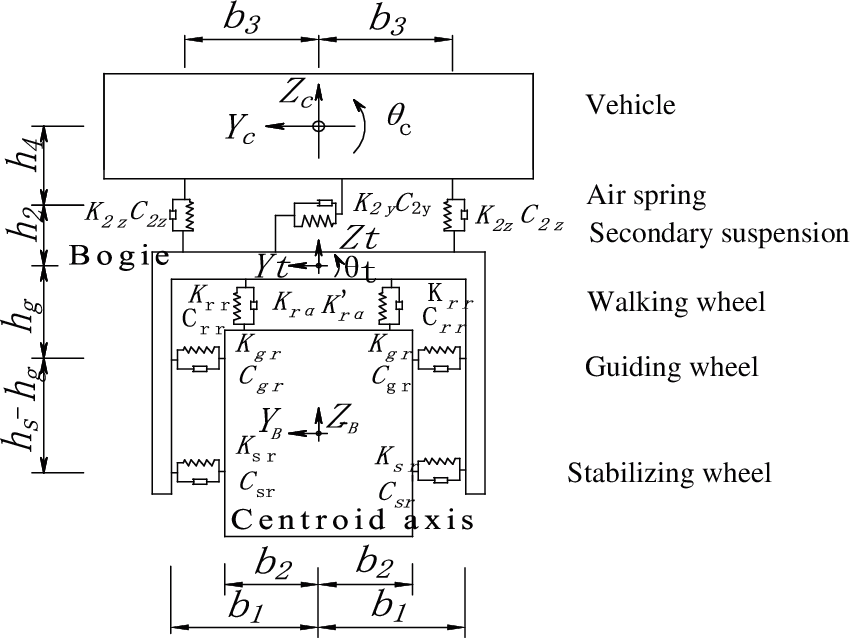
Figure 1: The model of straddle monorail vehicle
A single vehicle is divided into three rigid bodies, i.e., front bogie, rear bogie, and vehicle body. The whole vehicle can be simplified into 15 degrees of freedom, including the up and down motion, lateral movements, nodding, shaking and rolling motions of the front bogie, rear bogie, and vehicle body. Besides, all of these movements are independent to each other.
The curved beam is divided into several elements, and each node is divided into six degrees of freedom. The pier column and covered beam are simulated using ordinary beam element, while the supports are simulated by master-slave node. In addition, the lumped mass matrix is used in the curved beam elements, and the damping of bridge vibration system is assumed as a Rayleigh damping. The vibration equation of the curved bridge is:
2.3.1 Curvilinear Moving Coordinate System
The direction of a vehicle changed continuously, as it travels along the curved track beam. Hence, a vehicle curvilinear moving coordinate system is established. Taking the direction of track beam centroid as the X-axis, the curvilinear moving coordinate systems of vehicle and bogie are shown in Fig. 2.
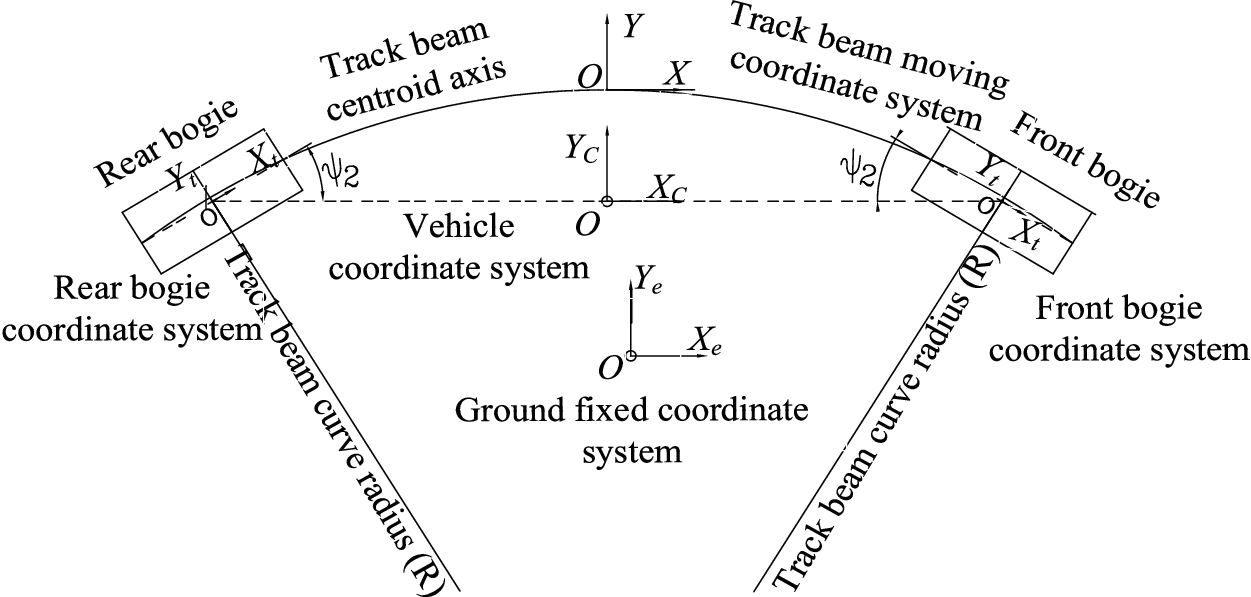
Figure 2: The curvilinear moving coordinate system
The wheel-track deformation caused by the curve is shown in Fig. 3.
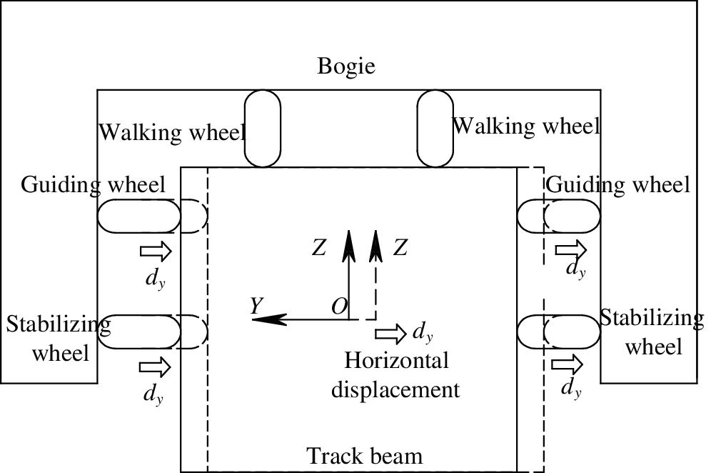
Figure 3: The wheel-track deformation caused by curve
The angular deformation is observed on a track beam, due to the superelevation of curve. Moreover, radial deformation appear on the guiding wheel and stabilizing wheel, while for the walking wheels, vertical deformation is observed. The wheel-rail deformation caused by superelevation is shown in Fig. 4.
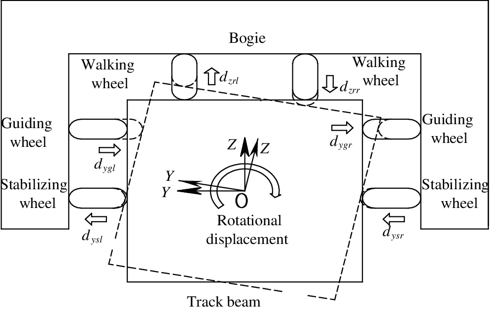
Figure 4: The wheel-track deformation caused by superelevation
The radial action of guiding wheel and stabilizing wheels, as well as the lateral action of walking wheels, are caused by the curve. For the ease of analysis, a virtual body is established on a contact surface between the wheel and the track beam. There is no stiffness and mass on the virtual bodies, and it contact the surface of the track beam, the displacement of the virtual body can be expressed as follows:
Furthermore, the wheel-rail forces increase by the curve, including the radial forces of guiding wheels and stabilizing wheels, the radial and lateral forces of walking wheels, and the aligning torque of walking wheels. The increased radial force of guiding wheel and stabilizing wheels is
2.3.3 Curve Superelevation Additional Force
Similar to ordinary railway bridges, when monorail vehicles are on curved lines, there is also additional force of curve superelevation.
It is observed that the inertia forces for vehicle and bogie are also affected by the curve. According to the theory of locomotive and vehicle dynamics, the vibration acceleration of vehicle and bogie is expressed by the vector product. Considering the bogie as an example, the inertial force for the lateral movement of bogie is
2.3.5 Monorail Vehicle-Curved Beam Vibration Equation
By integrating Eqs. (1) and (2), the coupling vibration equations for monorail vehicle-curved beam are established on a curvilinear moving coordinate system.
2.4 Solution Procedure of VBC Vibration
From the vibration equations of monorail vehicle-curved beam, it can be seen that the vibration equations of vehicle and bridge are related to each other through wheel-rail forces. Likewise, the force acting on each subsystem is related to the vibration response of another subsystem, which requires the solution to be solved iteratively in each time step. The step-by-step integral iterative method to solve the dynamic response of vehicle-bridge is shown in Fig. 5.
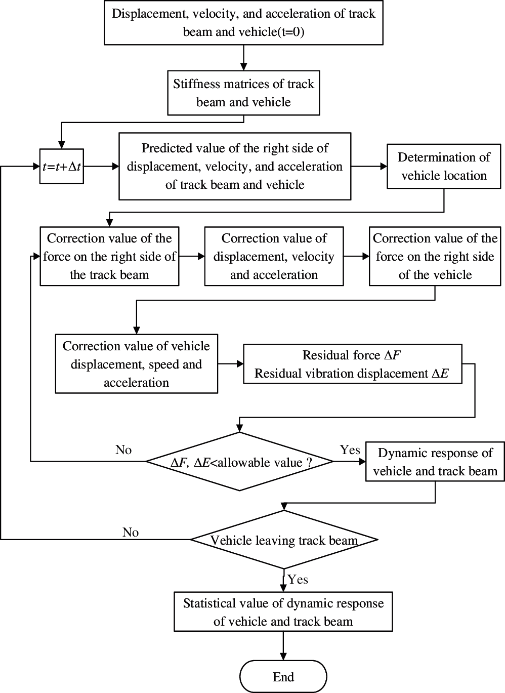
Figure 5: The step-by-step integral iterative method for dynamic response of vehicle-bridge
The adopted solution process in this work is demonstrated as follows:
(a) In each time step, vibration displacement, velocity, and acceleration of the vehicle and track beam subsystem are solved by Newmark-
(b) The predictor-correction method is used for the iterative analysis. The vehicle-bridge vibration and coupling force at time t are taken as the predicted values at time
(c) In each time step, the coupling force between vehicle and bridge, and the vibration displacement of the two subsystems, are taken as the convergence conditions for next iteration. The criteria for iterative convergence is as follows:
where u is the vehicle and track beam vibration displacement. F is the VBC force, i and I −1 are the current iteration and the last iteration, respectively. In addition, the time step is 0.0001 s and E is the given relative error with a value of 0.01%.
The Chongqing Jiao-xin is the first straddle monorail transit line built in China, with a length of 17.41 km. Likewise, most of the horizontal alignments are curved, with a minimum horizontal radius of 100 m and maximum longitudinal slope of 6%. Moreover, the maximum design speed is 75 km/h. The monorail viaduct is a simply supported structure, with a basic span of 20–24 m, main beam width of 0.85 m, and height of 1.5 m.
Progressively, following the opening of Jiao-Xin line to traffic, Chongqing Rail Transit Corporation conducted a dynamic load test [20]. An actual passenger train was used in the test, where the train included four vehicles. Accordingly, to compare the test results with the theoretical values, VBC vibration software is compiled on Compaq Visual Fortran 6.5 platform based on the VBC vibration model and the established numerical algorithm. A prestressed concrete (PC) track beam with a radius of 150 m and a span of 20 m is simulated.
Based on the vehicle parameters of an operation line in Japan [21], the number of passengers is estimated as 9 persons/m2, where the weight of a person is 50 kg. The calculation model of VBC vibration is shown in Fig. 6.
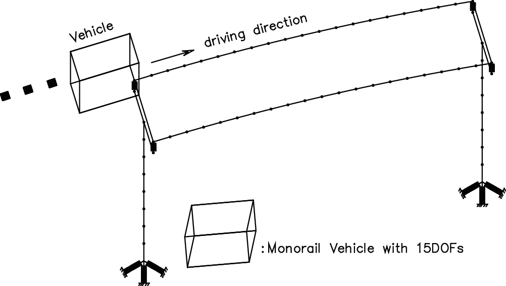
Figure 6: The calculation model of VBC vibration
There is no power spectrum function of PC track beam at home and abroad, and the track irregularities are of great influence to the VBC vibration. Therefore, the track irregularity simulation is divided into 4 working conditions. In first working condition, the track irregularity is ignored. For the second working condition, the track irregularity on the top and lateral sides of a track beam is simulated according to the power spectrum of steel beam track irregularity [21], and is recorded as “irregularity 1”. The third working condition referred to the irregularity on the top and lateral sides of a track beam, which is recorded as “irregularity 2”. Among them, the top irregularity is simulated using the track spectrum of Grade 6 in America, as shown in Fig. 7, while the lateral irregularity is simulated by the power spectrum of steel beam track irregularity [21], as shown in Fig. 8. Lastly, the fourth working condition is the test results.
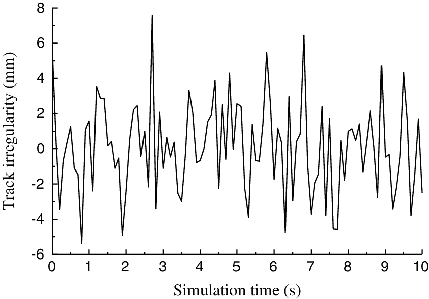
Figure 7: The track irregularity power spectrum of Grade 6
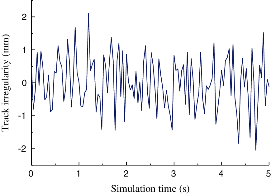
Figure 8: The power spectrum of track irregularity of steel beam
The tests were carried out at the speeds of 10, 20, 30, 40, 50, 60 and 65 km/h, respectively. Similarly, the vibration acceleration in the middle span of a track beam for all speed values, and the vehicle vibration acceleration for the last five speed values, were collected.
3.1 Influence of Irregularity and Speed on VBC Vibration
The variations in vertical vibration acceleration (VVA) and lateral vibration acceleration (LVA) in the middle span of a track beam are shown in Figs. 9 and 10, respectively. From the comparison of test and numerical simulation results, it can be seen that: ① The mid-span vibration acceleration of a track beam increases with an increase in vehicle speed, and fluctuates at the speeds of 30 and 60 km/h. ② For a vehicle speed larger than 30 km/h, the test results for VVA in the middle of a track beam are between the numerical simulation results of “irregularity 1” and “irregularity 2”. However, the test results for LVA in the middle of track beam are consistent with the simulation results of “irregularity 1” and “irregularity 2”. ③ Track irregularity results in an increase in the vibration acceleration of a track beam, significantly. ④Test results for LVA of the track beam exceed the limit value of 1.40 m/s2 at a vehicle speed larger than 40 km/h, hence the speed must be slowed down on a curve with small radius.
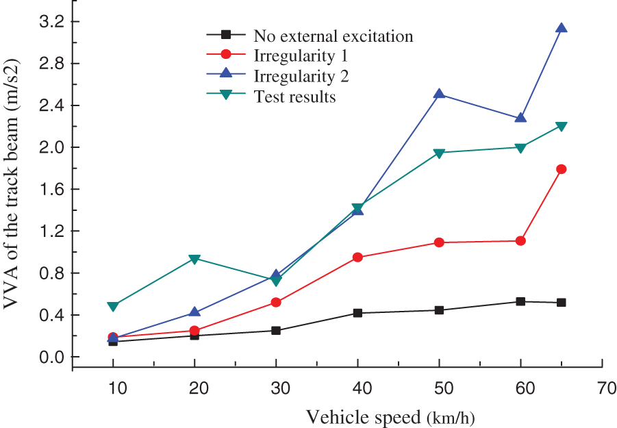
Figure 9: The VVA of the track beam
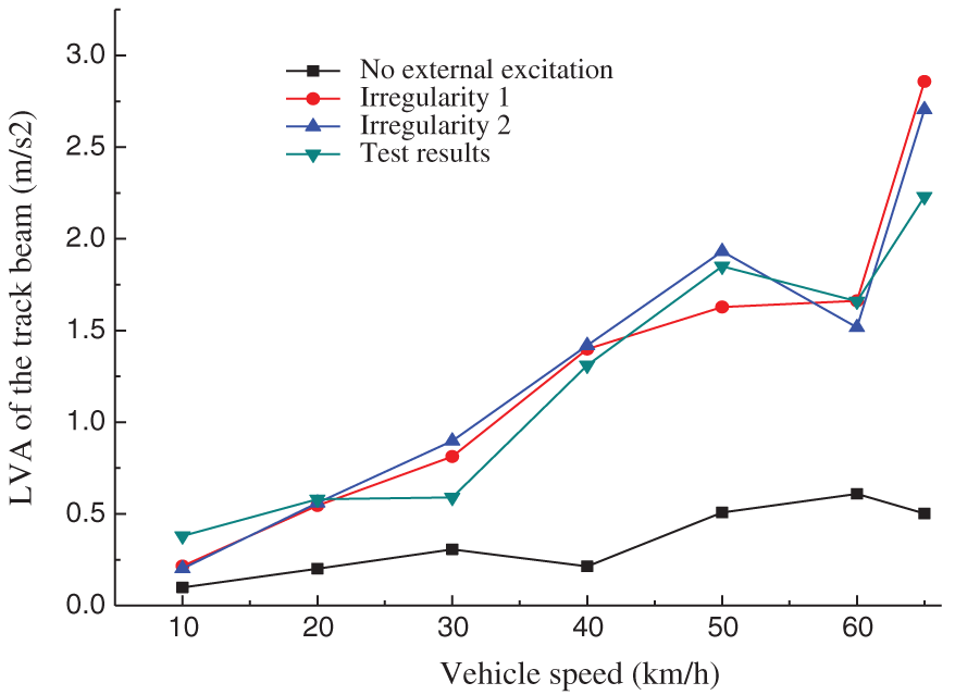
Figure 10: The LVA of the track beam
The VVA and LVA changes of the vehicle are shown in Figs. 11 and 12. The relevant comparison of test and numerical simulation results reveals that: ① Test results of VVA are slightly larger than the simulated results, however, the trend of VVA with the vehicle speed is consistent. In addition, the test results of LVA are almost consistent with the simulation results. ②Track irregularity is observed as an important excitation source for vehicle vibration, which resulted in an increase of vehicle vibration. ③ The LVA of vehicle shows an increasing trend with the vehicle speed, nevertheless, the VVA of vehicle varied insignificantly with the vehicle speed. ④ Both VVA and LVA satisfy the specified requirements with different vehicle speeds.
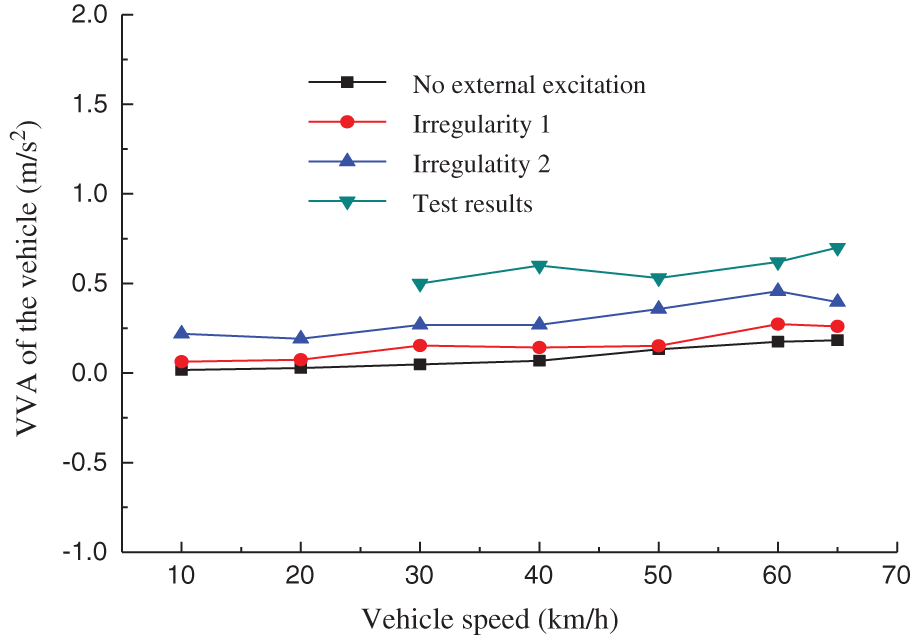
Figure 11: The VVA of the vehicle
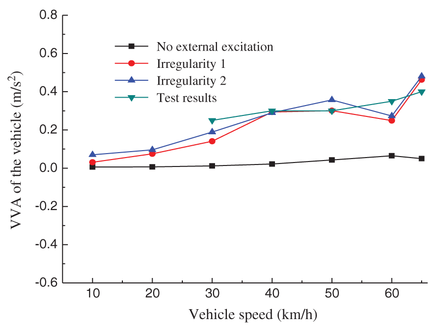
Figure 12: The LVA of the vehicle
Figs. 9–12 show that the vibrations of track beam and vehicle are substantially affected by the vehicle speed and track irregularity. Under the two kinds of irregularities (“irregularity 1”, “irregularity 2”), simulated values of lateral vibration of track beam and vehicle are consistent with the test values, and the lateral irregularity of PC track beam is close to that of steel beam. On the other hand, the vertical vibrations of track beam and vehicle are observed to lie between the two kinds of irregularities, where the top irregularity of PC track beam is between that of steel beam and Grade 6.
In general, test results of Chongqing Jiao-Xin line are consistent with the simulation results, which show that the VBC program compiled in this study is effective and the VBC vibration analysis of curved beam is correct, which can be potentially used for the VBC vibration analysis of straddle monorail transit.
3.2 Influence of Curve Radius on VBC Vibration
The test results show that the track irregularity and vehicle speed are the key factors affecting the vibration of vehicle-bridge, while keeping the curve radius of test span fixed. Hence, the influence of a curve on the dynamic performance of monorail transit cannot be reflected properly. Accordingly, taking the test span as an example, the influence of curve radius on VBC vibration is analyzed under the assumption that the vehicle running speed is 50 km/h, while ignoring the track irregularity. When the curve radius is 50–150 m, the superelevation is 12%. In addition, for the curve radius values of 250, 350, 450, 550, 650, 750 and 850 m, the superelevation is 8%, 6%, 4%, 3.5%, 3.0%, 2.5% and 2.0%, respectively. The vertical vibration displacement (VVD), lateral vibration displacement (LVD), VVA and LVA of the middle span of the track beam and the vehicle are shown in Figs. 13–16.
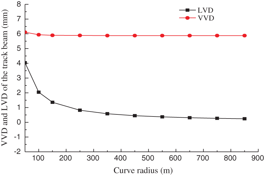
Figure 13: The VVD and LVD of track beam
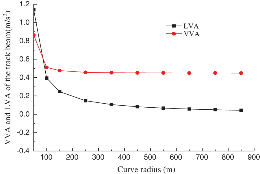
Figure 14: The VVA and LVA of track beam
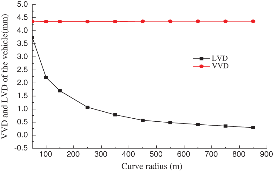
Figure 15: The VVD and LVD of vehicle
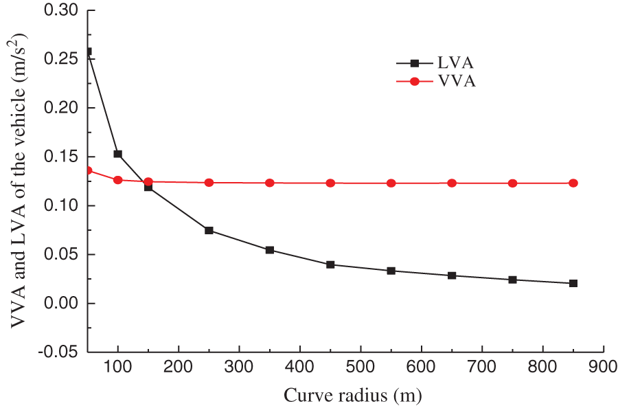
Figure 16: The VVA and LVA of vehicle
The analysis reveals that: ① The curve radius is an important factor for the vibration of track beam and vehicle. As the curve radius increases, vibration of track beam and vehicle decreases gradually, and tends to be stable. ② The influence of curve radius on the lateral vibration of track beam and vehicle is more significant than the vertical vibration. ③ When R ≤ 200 m, the lateral and vertical vibrations of the track beam and vehicle decrease significantly with the curve radius. However, when 200 < R < 600 m, the lateral and vertical vibrations of the track beam and vehicle decrease slowly with the curve radius. Lastly, for R ≥ 600 m, the lateral and vertical vibrations of the track beam and vehicle tend to be stable.
The VBC vibration of straddle monorail curved girder bridge and the concerned factors of VBC were studied in this work. The influences of curve radius, vehicle speed, and track irregularity on vehicle and bridge vibrations were analyzed. The main conclusions can be summarized as follows:
(1) Curve radius, track irregularity, and vehicle speed are of great influence to the VBC vibration of monorail curved beam. Track irregularities result in a significant increase in the vibration of track beam and vehicle.
(2) As the vehicle speed increases, the mid-span vibration acceleration of the track beam increases, and fluctuates at the speeds of 30 and 60 km/h.
(3) As the curve radius increases, the lateral and vertical vibrations of the vehicle-bridge decrease and stabilize. When R ≤ 200 m, the lateral and vertical vibrations of the track beam and vehicle decrease significantly with the curve radius. When 200 < R < 600 m, the lateral and vertical vibrations of the track beam and vehicle decrease slowly with the curve radius. When R ≥ 600 m, the lateral and vertical vibrations of the track beam and vehicle tend to be stable.
(4) The test results of Chongqing Jiao-Xin line are consistent with the simulation results, which show that the VBC program compiled in this study is effective, and the VBC vibration analysis of curved beam is correct. Likewise, it can be used for the VBC vibration analysis of straddle monorail transit.
Funding Statement: The authors gratefully acknowledge the partial support of this research by the Tianjin Natural Science Foundation (Nos. 18JCQNJC08300, 18JCYBJC90800), the National Natural Science Foundation of China (No. 52108333), Tianjin Transportation Science and Technology Development Plan (2021–20), the Key Laboratory of Road Structure and Materials Transportation Industry (No. 310821171114), the Innovation Capability Support Plan of Shaanxi Province (No. 2019KJXX-036), the Scientific Research Project of Tianjin Education Commission (No. 2020KJ038), and the Department of Science and Technology of Shaanxi Province Focuses on Research and Development of General Project Industrial Field (No. 2020GY318).
Conflicts of Interest: The authors declare that they have no conflict of interest to report regarding the present study.
1. Matsuokaa, K., Kaitob, K., Sogabec, M. (2020). Bayesian time–frequency analysis of the vehicle–bridge dynamic interaction effect on simple-supported resonant railway bridges. Mechanical Systems and Signal Processing, 135, 106373. DOI 10.1016/j.ymssp.2019.106373. [Google Scholar] [CrossRef]
2. Majka, M., Hartnett, M. (2008). Effects of speed, load and damping on the dynamic response of railway bridges and vehicles. Computers & Structures, 86(6), 556–572. DOI 10.1016/j.compstruc.2007.05.002. [Google Scholar] [CrossRef]
3. Antolín, P., Zhang, N., Goicolea, M. J., Xia, H., Astiz, M. A. (2013). Consideration of nonlinear wheel–rail contact forces for dynamic vehicle-bridge interaction in high-speed railways. Journal of Sound and Vibration,332(5), 1231–1251. DOI 10.1016/j.jsv.2012.10.022. [Google Scholar] [CrossRef]
4. Yang, H., Chen, Z., Li, S., Zhang, H., Fan, J. (2015). An integrated coupling element for vehicle-rail-bridge interaction system with a non-uniform continuous bridge. Acta Mechanica Solida Sinica, 28(3), 313–330. DOI 10.1016/S0894-9166(15)30018-5. [Google Scholar] [CrossRef]
5. Xiao, X., Sun, Z., Shen, W. (2020). A kalman filter algorithm for identifying track irregularities of railway bridges using vehicle dynamic responses. Mechanical Systems and Signal Processing, 138, 106582. DOI 10.1016/j.ymssp. [Google Scholar] [CrossRef]
6. Cantero, D., Karoumi, R. (2016). Numerical evaluation of the mid-span assumption in the calculation of total load effects in railway bridges. Engineering Structures, 107, 1–8. DOI 10.1016/j.engstruct.2015.11.005. [Google Scholar] [CrossRef]
7. Liu, G., Jang, B., Zhou, Z., Zeng, Q. (2014). Effect of wheel pressure on vibration of straddle monorail transit vehicle-bridge system. Advanced Materials Research, 3149, 542–546. DOI 10.4028/www.scientific.net/AMR.919-921.542. [Google Scholar] [CrossRef]
8. Du, Z., Wen, X., Zhao, D., Xu, Z., Chen, L. (2017). Numerical analysis of partial abrasion of the straddle-type monorail vehicle running tyre. Transactions of FAMENA, 41(1), 99–112. DOI 10.21278/TOF. [Google Scholar] [CrossRef]
9. Du, Z., Zhou, J., Zhen, Y., Jin, B. (2018). The research on operational reliability evaluation of straddle-type monorail vehicle. Systems Science & Control Engineering, 6(1), 537–546. DOI 10.1080/21642583.2018.1550690. [Google Scholar] [CrossRef]
10. Yang, Z., Du, Z., Xu, Z., Zhou, J., Hou, Z. (2020). Research on dynamic behavior of train dynamic model of straddle-type monorail. Noise & Vibration Worldwide, 51(11), 195–207. DOI 10.1177/0957456520947998. [Google Scholar] [CrossRef]
11. Zhuravlev, V. P. (2010). Impact self-excited vibrations of linear motor. Mechanics of Solids, 45(4), 497–500. DOI 10.3103/S0025654410040011. [Google Scholar] [CrossRef]
12. Zhou, J., Du, Z., Yang, Z., Xu, Z. (2019). Dynamics study of straddle-type monorail vehicle with single-axle bogies-based full-scale rigid-flexible coupling dynamic model. IEEE Access, 99, 1. DOI 10.1109/Access.6287639. [Google Scholar] [CrossRef]
13. Zhou, J., Du, Z., Yang, Z., Xu, Z. (2020). Dynamic parameters optimization of straddle-type monorail vehicles based multiobjective collaborative optimization algorithm. Vehicle System Dynamics, 58(3), 357–376. DOI 10.1080/00423114.2019.1578384. [Google Scholar] [CrossRef]
14. Wang, D., Li, X., Wang, Y., Hu, Q. (2020). Dynamic interaction of the low-to-medium speed maglev train and bridges with different deflection ratios: Experimental and numerical analyses. Advances in Structural Engineering, 23(11), 2399–2413. DOI 10.1177/1369433220913367. [Google Scholar] [CrossRef]
15. Xin, L., Li, X., Zhang, J., Zhu, Y., Xiao, L. (2020). Resonance analysis of train–track–bridge interaction systems with correlated uncertainties. International Journal of Structural Stability and Dynamics, 20(1), 27. DOI 10.1142/S021945542050008X. [Google Scholar] [CrossRef]
16. He, Q., Cai, C., Zhu, S., Wang, K., Zhai, W. (2020). An improved dynamic model of suspended monorail train-bridge system considering a tyre model with patch contact. Mechanical Systems and Signal Processing, 144, 106865. DOI 10.1016/j.ymssp.2020.106865. [Google Scholar] [CrossRef]
17. Wang, H., Zhu, E., Chen, Z. (2017). Dynamic response analysis of the straddle-type monorail bridge-vehicle coupling system. Urban Rail Transit, 3(3), 172–181. DOI 10.1007/s40864-017-0069-x. [Google Scholar] [CrossRef]
18. Youcef, K., Sabiha, T., Mostafa, D. E., Ali, D., Bachir, M. (2013). Dynamic analysis of train-bridge system and riding comfort of trains with rail irregularities. Journal of Mechanical Science and Technology, 27(4), 951–962. DOI 10.1007/s12206-013-0206-8. [Google Scholar] [CrossRef]
19. Naeimi, M., Tatari, M., Esmaeilzadeh, A. (2015). Dynamics of the monorail train subjected to the braking on a straight guideway bridge. Archive of Mechanical Engineering, 62(3), 363–376. DOI 10.1515/meceng-2015-0021. [Google Scholar] [CrossRef]
20. Shi, Z., Pu, Q. H., Gao, Y. F., Xia, Z. G. (2008). Research on dynamic test of chongqing straddle monorail transportation system. Journal of Vibration and Shock, 27(12), 101–106. DOI 10.13465/j.cnki.jvs.2008.12.014. [Google Scholar] [CrossRef]
21. Lee, C. H., Kawatani, M., Kim, C. W., Nishimura, N., Kobayashi, Y. (2006). Dynamic response of a monorail steel bridge under a moving train. Journal of Sound and Vibration, 294(3), 562–579. DOI 10.1016/j.jsv.2005.12.028. [Google Scholar] [CrossRef]
 | This work is licensed under a Creative Commons Attribution 4.0 International License, which permits unrestricted use, distribution, and reproduction in any medium, provided the original work is properly cited. |