| Computer Modeling in Engineering & Sciences |
DOI: 10.32604/cmes.2022.018535
ARTICLE
Experimental and Numerical Study on Mechanical Properties of Z-pins Reinforced Composites Adhesively Bonded Single-Lap Joints
1School of Electromechanical Engineering, Lingnan Normal University, Zhanjiang, 524048, China
2Key Laboratory of Advanced Ship Materials and Mechanics, Harbin Engineering University, Harbin, 150001, China
3Department of Engineering Mechanics, College of Aerospace and Civil Engineering University, Harbin, 150001, China
*Corresponding Author: Yinhuan Yang. Email: yangyh80@163.com
Received: 31 July 2021; Accepted: 27 October 2021
Abstract: The mechanical properties of Z-pins reinforced composites adhesively bonded single-lap joints (SLJs) under un-directional tension loading are investigated by experimental and numerical methods. Three kinds of joint configurations, including SLJs with three/two rows of Z-pins and “I” array of Z-pins, are investigated by tension test. The failure modes and mechanism of reinforced joints with different Z-pins numbers and alignment are analyzed, and the comparison is performed for the failure strengths of no Z-pins and Z-pins reinforced joints. According to experimental results, failure modes of three kinds of joints are all mixed failure. It turns out that the Z-pins are pulled out ultimately. The strength of joints of more Z-pins at the end of the overlap area is relatively bigger for the joint of the same Z-pins numbers. The strength of joints with Z-pins compared with non Z-pins joints is growing at 16%. Finally, the three-dimensional distribution of interfacial stress in the lap zone of three kinds of Z-pins reinforced joints is simulated, and the numerical results are in good agreement with the experimental results. It is effective that the numerical calculation of stress analysis is verified.
Keywords: Z-pins reinforced composite single-lap joint (SLJ); failure mode and strength; un-directional tension test; interfacial stress
Composites are extensively applied to aerospace, automobile, ship, ocean and other fields with the advancement of science and technology. Bonding structure is the most widely used connection form in composite structures, but under the circumstances of overload, environmental transformation and fatigue, there is a hidden danger of catastrophic damage to the joint. Especially under in-plane tensile load, the joint is seriously affected by shear stress concentration, which can lead to delamination damage of composites. Therefore, researchers have developed various three-dimensional connection technologies to improve the strength of the joint [1–4]. The enlarged core-to-face-sheet bond area has been used to improve the connection strength for the lattice truss sandwich structures [5,6]. Xiong et al. [7,8] studied the curved lattice truss by connecting rods and bonding area to ensure the high bonding properties. Wu et al. [9] reported the work that the struts are reinforced with unidirectional fibers and lattice core is strengthened by end frames between various nodes. As a new technology, Z-pins reinforced technology is applied to the field of composite toughening. With the advantages of easy manufacture and lower cost, slender cylindrical nails inserted into the body of the adherend can enhance the bearing capacity of the joint. Basic research mainly focuses on the influence of Z-pins on material properties, including not only the delamination resistance, rigidity in thickness direction, improvement of connection strength and joint extrusion strength, but also the reduction of in-plane properties of materials caused by Z-pins implantation (such as tensile strength, compressive strength, bending strength and fatigue properties) [10].
The study on the mechanical properties of Z-pins reinforced composites has been more mature [11–15] in recent years. In the field of Z-pins toughening, study on mechanical behaviors of joints with Z-pins reinforced composites needs to be further improved. Liao et al. [16] studied the low-speed impact behavior of Z-pins implantation direction on the effect of composite laminates on inhibiting delamination damage and internal defects. Zhang et al. [17,18] improved the shear properties of 2D C/SiC Z-pins joints by optimizing the microstructure characteristics of joints, such as Z-pins porosity, density, diameter and ply direction. Nguyen et al. [19] proposed a numerical method to capture the geometric, material and damage characteristics of metal pins penetrating the thickness of metal composites. The model described the failure mode and energy of pins and proved that it was in good agreement with the experimental results. Zu et al. [20] studied the effects of geometric parameters and ply sequences on the mechanical properties of pin-loaded metal composite joints. Koh et al. [21] carried out experimental investigations on strengthening mechanisms and structural properties of T-joints with Z-pins reinforced composites. Pulling off experiments are carried out on non Z-pins reinforced joints and reinforced joints with Z-pins volume content of 0.5%, 2% and 4%, respectively. The results show that the initial failure load and stiffness of joints are not enlarged by Z-pins toughening, but energy absorption capacity, destroy displacement and the ultimate failure strength can be effectively improved. Bianchi et al. [22] proposed a finite element model to analyze the strength property, structural deformation and delamination fracture behavior of Z-pins reinforced composites T-joints. Nanayakkara et al. [23] carried out experimental research and analysis on the strength and toughness of Z-pins reinforced sandwich composite T-joint. Nguyen et al. [24] studied the pins reinforced metal and composite joint, and compared the mechanical behavior of a single pin and multiple carbon fiber pins reinforced joints by means of theoretical analysis, numerical simulation and experimental means. Bodjon et al. [25] discussed the characteristics of hybrid bonding-pin connection and bonding-bolt connection, respectively. Ren et al. [26] predicted the dynamics fracture process as well as failure modes of bonded joints accurately by establishing a three-dimension-multiscale adhesive process zone model. Tao et al. [27] studied the failure mechanism and static tensile strength of ceramic-matrix composite single-lap joints with various bonded lengths. Two final failure modes with the fracture of the lap plate and Z-pins separated from the lap plate are given and the strength of joints is well predicted.
For further research of the mechanical behavior of Z-pins reinforced composite SLJs, tensile experiments of unidirectional static load and numerical studies are carried out for Z-pins reinforced SLJs of T700/TDE86 unidirectional composite, and the failure modes and failure mechanisms of three types of Z-pins reinforced composite SLJs are analyzed. The effect of the arrangement and number of Z-pins with regard to strength of the joint is studied, and the three-dimensional distribution of interfacial stress in the lap area of three types of Z-pins reinforced SLJs is numerically simulated. The innovation of this study is to reveal the strengthening mechanism of Z-pins in joint failure, compare the strength of Z-pins reinforced joints with or without Z-pins, conduct experimental research on Z-pins reinforced joints with different arrangement modes, obtain the law of influence of Z-pins distribution mode on joint failure, and analyze the law of distribution of interfacial stress field of Z-pins reinforced single-lap joint.
The adherend and Z-pins of SLJ adopt T700/TDE86 epoxy-resin-matrix unidirectional laminated composite, and the adhesive is J39 epoxy adhesive. The geometric dimension of joint is as follows:
Z-pins is 4.3 mm in length and 0.8 mm in diameter. The adhesive layer is 0.3 mm in thickness. The laminate is 2 mm in thickness and 25 mm in width. The whole length and the overlapping length of the joint are 200 mm and 20 mm, respectively. The arrangement form and spacing of Z-pins of three kinds of joint configurations are shown in Fig. 1.
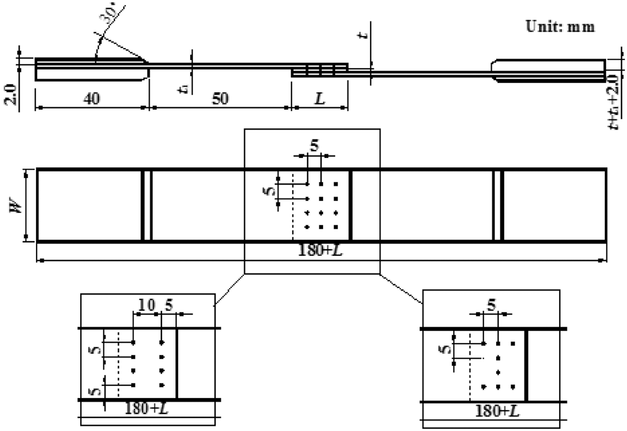
Figure 1: Z-pins reinforced composites SLJs (t1 is the thickness of adherend, t is the thickness of adhesive layer, and L is the lap length)
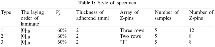
The types of test pieces are shown in Table 1. The fiber volume content of composite is 60%. The laying order of laminate is [0]10. Three kinds of joint configurations, including SLJ with three/two rows of Z-pins and “Ⅰ” array of Z-pins, are investigated by tension test. There are five samples of each type. The Z-pins array and geometric dimensions of various types of Z-pins reinforced composite SLJs are given in Fig. 1. Two rows of Z-pins reinforced SLJ and three rows of Z-pins reinforced SLJ have the same Z-pins arrangement at both ends of the overlapping area. The number of Z-pins of Z-pins reinforced SLJ arranged in “Ⅰ” shape is the same as that of the two rows of Z-pins reinforced SLJs.
3 Test Piece Preparation Process
The preparation process of Z-pins reinforced composite SLJs specimens is as follows: (1) Cure the unidirectional laminate; (2) Design the mold according to the shape and size of the lap joint, clean the bonded positioning steel plate mold with acetone, and then evenly apply release agent on its surface; (3) Use acetone solution to clean the surface of the lap area of the laminate, apply primer and structural adhesive on the surface of the lap area of the laminate; (4) The two laminates are bonded and assembled on the bonding curing die; (5) Place the assembled bonding member together with the curing mold in the vacuum bag, extract the air to form negative pressure in the vacuum bag with the vacuum degree of 0.05 MPa. Heat the bonding member to 200°C at the heating rate of 2 °C/min, and apply a pressure of 0.35 MPa for insulation for two hours; (6) After the single-lap adhesive joint is solidified and formed, locate the center of the hole in the lap area according to the proposed scheme; (7) Punch holes with a probe, and then insert the pre-prepared carbon fiber nail; (8) Grind off the carbon fiber nails protruding from the surface of the upper and lower adherend, and then put the bonding member and its assembly die into the hot press; (9) Place the test piece flat in the oven, raise the temperature of the bonding member to 125°C at the heating rate of 1 °C/min, and apply a pressure of 0.25 MPa for insulation for one hour; (10) Cool naturally to room temperature and take out the test piece.
After the test piece is prepared, formed and stored at room temperature for more than 24 h, the tensile test can be carried out.
4 Uniaxial Tensile Test and Result Analysis
Test equipment and methods are shown in [28].
The interface morphology of three types of Z-pins reinforced SLJs after failure is shown in Fig. 2. The interface failure morphology of three rows of Z-pins reinforced SLJ is shown in Fig. 2a). Failure mode analysis of this kind of joint is shown in literature [23], which is our previous research. The interface morphology of two rows of Z-pins reinforced SLJs after failure is shown in Fig. 2b). The failure morphology shows that cohesive failure and interface failure is the major failure modes for this kind of joint, and with a small amount of fiber-tear failure. The fiber-tear failure occurs mainly on the lap plate between Z-pins along the direction of the lap length; the ultimate failure mode is still Z-pins separating from the lap plate. The interface failure morphology of the “Ⅰ” shaped Z-pins reinforced SLJs is shown in Fig. 2c). It is apparent that the interface failure is the major failure mode of this kind of joint and a few parts of cohesive failure occurs around the Z-pins along the direction of the lap length. Minor fiber-tear failure appears in the laminate between the Z-pins, and the ultimate failure of the joint is that the Z-pins are separated from the lap plate.
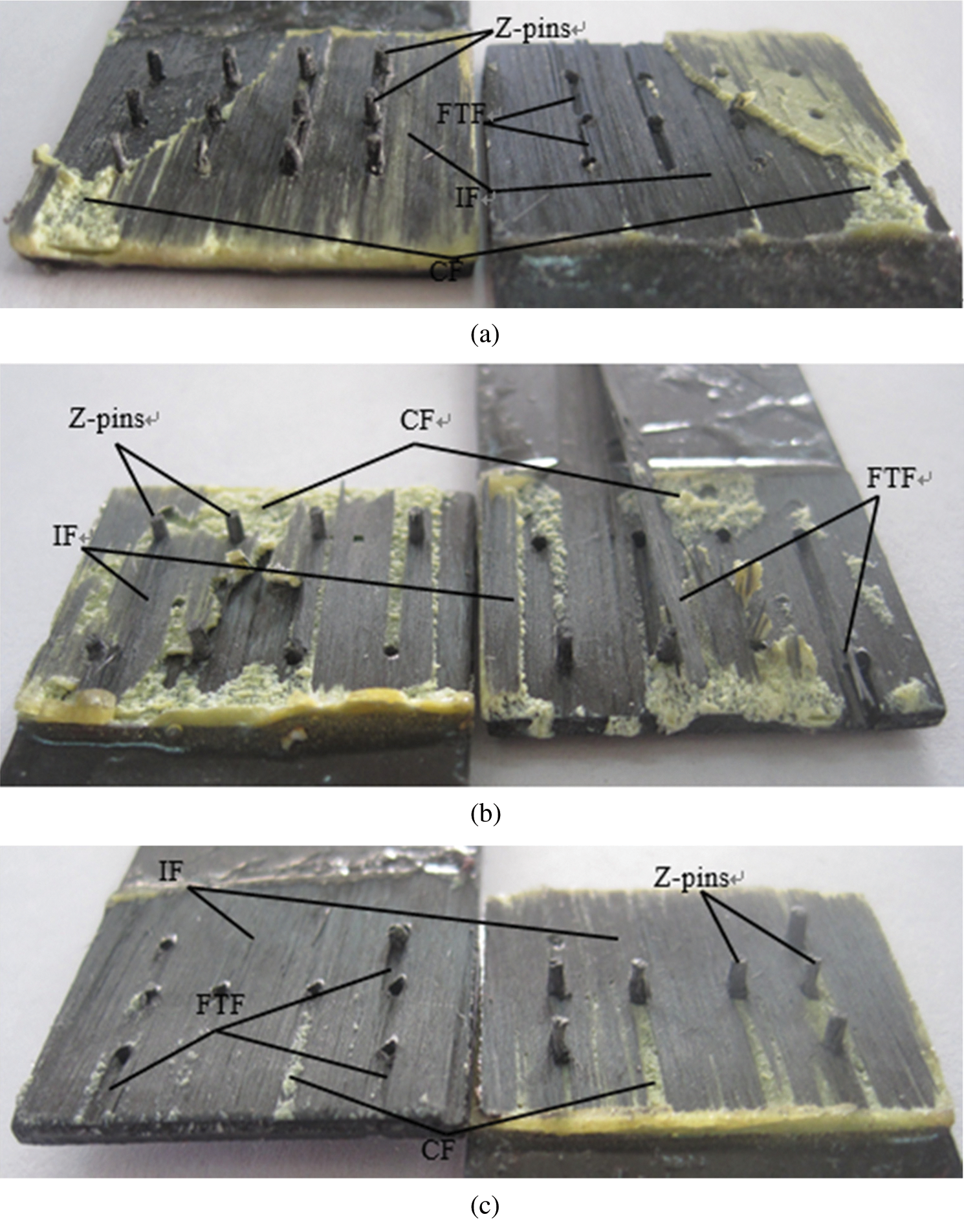
Figure 2: Failure modes of three types of Z-pins reinforced SLJs (IF—interface failure, FTF—fiber-tear failure, CF—cohesive failure) (a) SLJ with three rows of pins [28] (b) SLJ with two rows of pins c) SLJ with “Ⅰ” array of pins
Due to the asymmetry of single-lap joint structure, when subjected to unidirectional load, the joint interface is greatly affected by shear stress, so the joint failure is mainly interface failure and cohesive failure. During the implantation of Z-pins, a small part of fibers is broken during drilling, resulting in a small part of fiber-tear failure. At the same time, eccentric bending moment generates at the lap zone, and peeling occurs at the lap interface, which eventually leads to the pull-out failure of Z-pins.
The final failure mode of three types of joints is Z-pins separated from the lap plate with no pin fracture. The failure mode of such joints is strongly influenced by the interfacial peel stress and shear stress between the joint and Z-pins, and has a certain relationship with the material properties of adherend, Z-pins and adhesive. At the same time, the joint failure also has a certain influence on the degree of curing connection during the preparation of the test piece.
4.2 Analysis of Failure Mechanisms
The load-displacement curves of three kinds of Z-pins reinforced composites SLJs under static tensile load are investigated by the test. As shown in Fig. 3, it is obvious that the failure load values of five specimens of the same type of joints vary greatly due to dimensional error and manufacturing process error, such as Z-pins implantation, adhesive application, and other influencing factors.
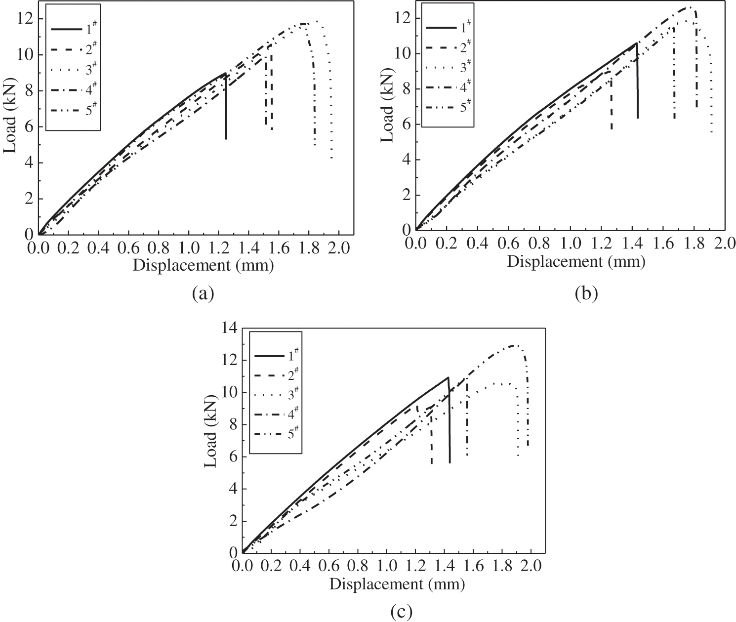
Figure 3: Load-displacement curves of three types of Z-pins reinforced composites SLJs (a) SLJs with three rows of pins [28] (b) SLJs with two rows of pins (c) SLJs with “Ⅰ” array of pins
As can be seen in Fig. 4, composite SLJs with two rows of pins have the greatest strength, three rows of Z-pins reinforced composite SLJs have the second strength, and composite SLJs with the “Ⅰ” array of Z-pins have the worst strength. Among them, the number of Z-pins set for the two rows of Z-pins reinforced SLJs is the same as that of joints with the “Ⅰ” type of Z-pins, but the positions distributed in the lap zone are different.
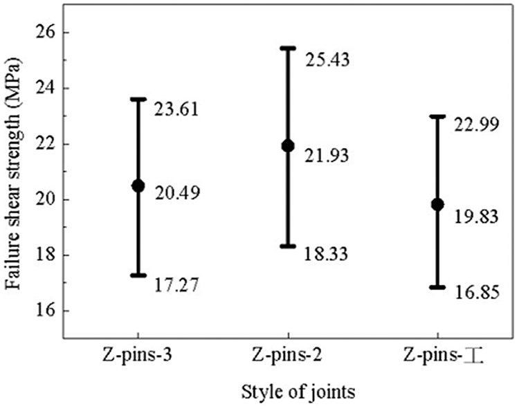
Figure 4: Failure shear strengths of all specimens for three kinds of Z-pins reinforced SLJs (SLJ with three rows of pins is referred to as Z-pins-3 for short; SLJ with two rows of pins is referred to as Z-pins-2 for short; SLJ with “Ⅰ” array of pins is referred to as Z-pins-Ⅰ for short.)
According to the experimental results, for joints with the same number of Z-pins, the joint with more Z-pins arranged at the end of the overlapping zone has relatively large strength. However, for joints with the same Z-pins arrangement, the strength of joints with a greater number of Z-pins is relatively small with the following reasons:
(1) The process of preparing Z-pins reinforced composite adhesive joint: drilling holes on the cured laminate, and secondary curing after implantation of Z-pins. This preparation process leads to excessive fiber fracture near the hole and destroys the integrity of the laminate. The more Z-pins, the smaller the distance between them, and the cracking of the lap plate between the two Z-pins is relatively serious, which affects the overall strength of the joint.
(2) There is relatively large stress concentration at the overlapping end of the joint. Therefore, setting Z-pins at the end will significantly increase the strength of the joint.
For Z-pins reinforced composite SLJs, since the geometric center of the joint structure is not on the same line as the action line of unidirectional load, the lap joint will emerge eccentric bending moment under unidirectional load, deform in the shear direction and peel off at the overlapping section and so on. Therefore, Z-pins will be affected by shear and peel stress, the final failure is breaking or pulling out. The ultimate failure mode is Z-pins pulling out from the lap plate, and fracture of Z-pins does not occur in each specimen in the test.
5 Comparison with Non Z-pins Reinforced Adhesive Joint
The experimental results of the strength of three types of Z-pins and non Z-pins reinforced composite SLJs [29] are shown in Fig. 5. It is distinct that the average strength of reinforced joints with Z-pins is greater than that reinforced joints with non Z-pins, and the strength of SLJs with two rows of Z-pins is 16% higher than that of reinforced composite SLJs with non Z-pins.
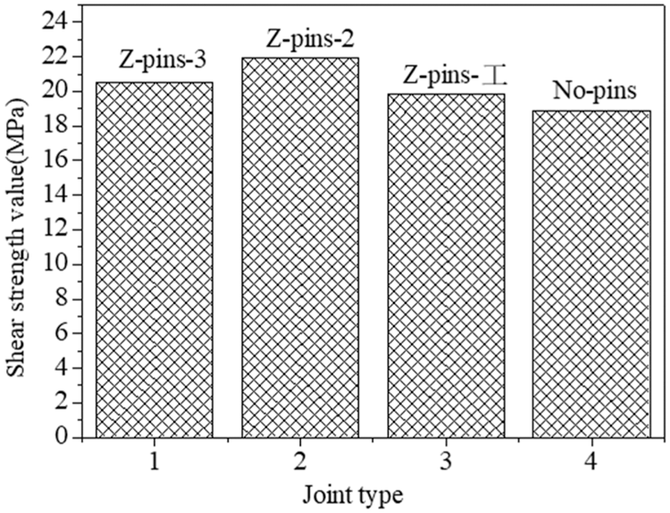
Figure 5: Failure shear strength of three kinds of SLJs with Z-pins and SLJs with non Z-pins
In order to make further efforts to investigate the failure mechanism of Z-pins reinforced adhesively bonded SLJs of T700/TDE86 composites under uniaxial tension, the interface stress in the lap zone of the joint is analyzed and calculated by ANSYS14.0 finite element software.
The static finite element analysis of structure is conducted. The adhesive layer, adherend and Z-pins are considered as elastic materials. The axial tensile load applied in the numerical simulation is 9 kN, applied load and constrained displacement are shown in reference [28]. The lap zone model takes the joint structure with two rows of Z-pins as an example in Fig. 6. The geometrical parameters and individual material properties of numerical models are identical to those of experimental samples, with the X, Y and Z axes being in the length, the width and thickness directions of the model, respectively.
Figure 6: Schematic of SLJ with two rows of pins
6.1 Unit Type and Material Parameters
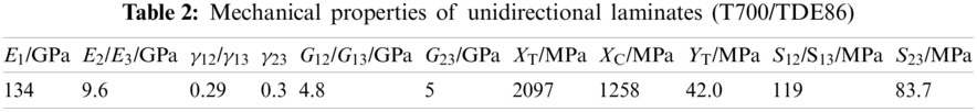
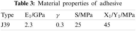
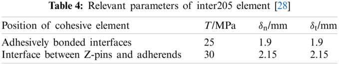
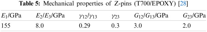
Adhesive layer, laminates and Z-pins are simulated and applied to solid45 elements. Since the implantation of Z-pins into the joint requires secondary curing and the fusion of resin matrix, it is approximately considered that the Z-pins and the joint are bonded. Therefore, Inter205 cohesive interface element, which shares nodes with the adjacent solid elements, is applied to express the interface between adhesive layer and laminates and between Z-pins and joint. The diagrammatic sketch of lap zone of the SLJ with two rows of pins is shown in Fig. 7. The mechanical properties of laminate, adhesive, the relevant parameters of cohesive element and Z-pins are shown in Tables 2–5, respectively.
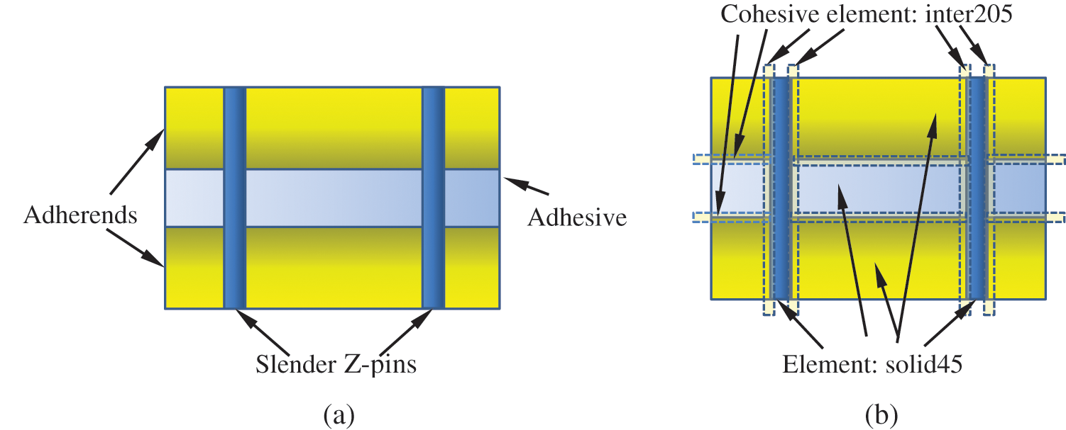
Figure 7: Diagrammatic sketch of overlapping zone of the SLJ with two rows of pins. (a) The lap zone structure of SLJ (b) Element type
The mesh of the numerical models of three types of SLJs with Z-pins is refined, as shown in Fig. 8, with the minimum element size of 0.125 mm and the maximum element size of 2 mm among them. The refined grid areas include Z-pins, around Z-pins and the ends of overlapping area of joints.
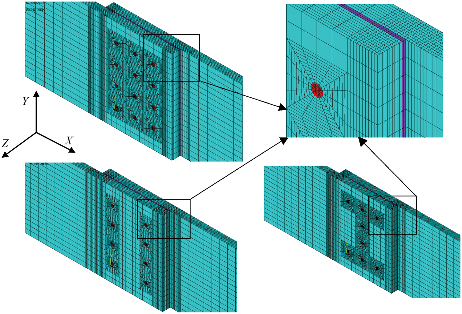
Figure 8: Meshes of the numerical models of three kinds of Z-pins reinforced joints
6.3 Three Dimensional Distributions of Interface Stress
For reinforced composite SLJ with three rows of Z-pins, the distribution of in-plane stress
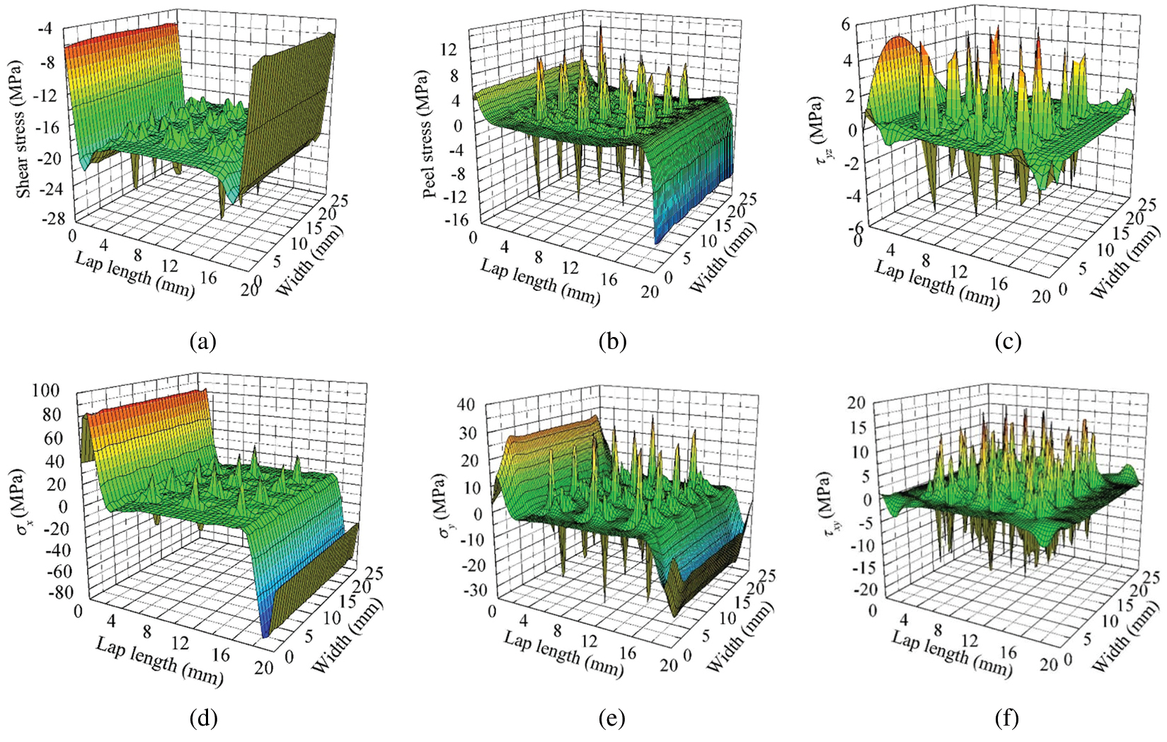
Figure 9: Stress distributions in upper interface of SLJ with three rows of pins (a)
According to the simulated results, it finds that the interfacial peel stress and shear stress are major stresses affecting the joint strength. For the two rows of Z-pins reinforced joints and “Ⅰ” shaped Z-pins reinforced joints, only the distributions of shear/peel stress of the interface layer in the overlapping area are given and shown in Figs. 10 and 11. It is evident that the distribution law of shear/peel stress in the interface layer is similar to that of three rows of Z-pins reinforced composite SLJ, which will not repeat here.
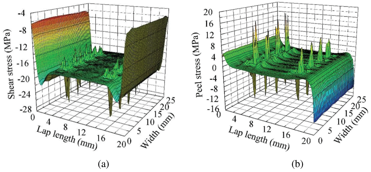
Figure 10: Stress/peel stress distributions in upper interface of Z-pins reinforced composites SLJ with two rows of pins (a)
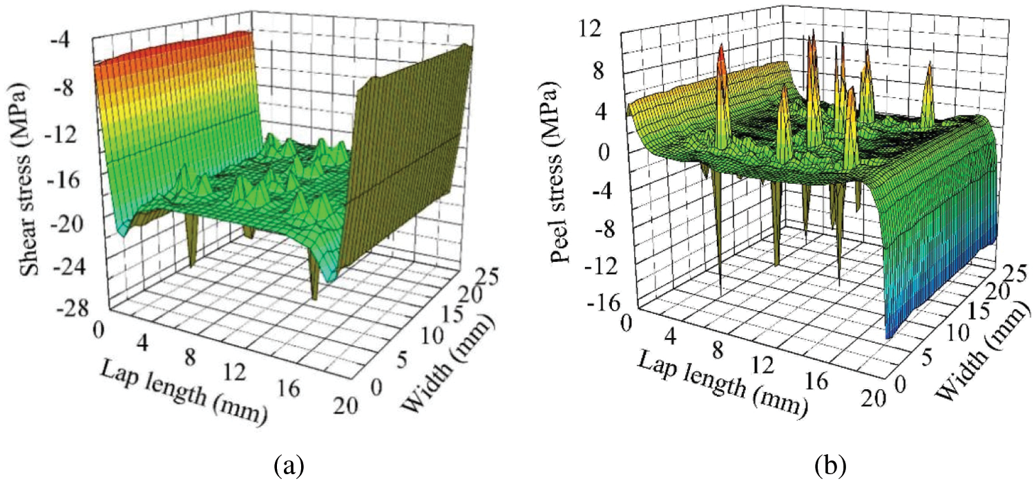
Figure 11: Shear/peel stress distributions in upper interface of Z-pins reinforced composites SLJ with “Ⅰ” array of pins (a)
Studying on the failure behavior of composites adhesively bonded SLJs with three different Z-pins arrangements by experimental and numerical analysis methods, the failure mode and failure mechanism of each joint are investigated and analyzed, and failure strengths of different types of Z-pins reinforced composite SLJs are compared with non Z-pins reinforced composite SLJs. The three-dimensional shear/peel stress distribution of the interface of three types of joints is simulated with a cohesive model.
(1) The failure modes of three kinds of joints are summarized as follows: reinforced SLJ with three rows of Z-pins takes thin-layer cohesive failure as the dominant failure mode, accompanied with a small amount of fiber-tear and interface failure; the major failure mode of reinforced SLJ of two rows Z-pins is an interface and cohesive failure, with a few parts of fiber-tear failure; interface failure occurs as the critical failure mode for reinforced SLJ of “Ⅰ” shaped Z-pins, with a less area of fiber-tear and cohesive failure. The ultimate failure mode of three types of joints is Z-pins separating out of the lap plate.
(2) The strength of joints with the same number of Z-pins shows that the strength of joints with more Z-pins at the end is relatively large; for the joints with more Z-pins in the whole lap zone, the strength of the joints is relatively small.
(3) Compared with the joint without Z-pins reinforcement, the strength of Z-pins reinforced joint increased by 16%.
(4) The stress field has obvious stress concentration around Z-pins, and the maximum peel stress and shear stress at the ends of the overlapping zone is less than that around Z-pins. It can obtain that the adhesive and adhesive layer around Z-pins is easy to damage first. In comparison with the experimental results, it is effective that the numerical calculation of stress analysis is verified.
Funding Statement: This work was supported by Natural Science Talents Program of Lingnan Normal University (No. ZL2021011).
Conflicts of Interest: The authors declare that they have no conflicts of interest to report regarding the present study.
1. Nzabonimpa, J. D., Hong, W. K., Kim, J. (2018). Experimental and non-linear numerical investigation of the novel detachable mechanical joints with laminated plates for composite precast beam-column joint. Composite Structures, 185, 286–303. DOI 10.1016/j.compstruct.2017.11.024. [Google Scholar] [CrossRef]
2. Ozel, A., Yazici, B., Akpinar, S., Aydin, M. D., Temiz, Ş. (2014). A study on the strength of adhesively bonded joints with different adherends. Composites: Part B, 62, 167–174. DOI 10.1016/j.compositesb.2014.03.001. [Google Scholar] [CrossRef]
3. Warzok, F., Allegri, G., Gude, M., Hallett, S. R. (2016). Experimental characterisation of fatigue damage in single Z-pins. Composites: Part A, 91, 461–471. DOI 10.1016/j.compositesa.2016.03.023. [Google Scholar] [CrossRef]
4. An, W. J., Kim, C. H., Choi, J. H., Kweon, J. H. (2019). Static strength of RTM composite joint with I-fiber stitching process. Composite Structure, 210, 348–353. DOI 10.1016/j.compstruct.2018.11.072. [Google Scholar] [CrossRef]
5. Xiong, J., Ma, L., Vaziri, A., Yang, J. S., Wu, L. Z. (2012). Mechanical behavior of carbon fiber composite lattice core sandwich panels fabricated by laser cutting. Acta Materialia, 60(13–14), 5322–5334. DOI 10.1016/j.actamat.2012.06.004. [Google Scholar] [CrossRef]
6. Xiong, J., Wang, B., Ma, L., Papadopoulos, J., Vaziri, A. et al. (2014). Three-dimensional composite lattice structures fabricated by electrical discharge machining. Experimental Mechanics, 54, 405–412. DOI 10.1007/s11340-013-9801-y. [Google Scholar] [CrossRef]
7. Xiong, J., Ghosh, R., Ma, L., Vaziri, A., Wang, Y. L. et al. (2014). Sandwich-walled cylindrical shells with lightweight metallic lattice truss cores and carbon fiber reinforced composite face sheets. Composite Part A, 56, 226–238. DOI 10.1016/j.compositesa.2013.10.008. [Google Scholar] [CrossRef]
8. Xiong, J., Ghosh, R., Ma, L., Ebrahimi, H., Hamouda, A. M. S. et al. (2014). Bending behavior of lightweight sandwich-walled shells with pyramidal truss cores. Composite Structures, 116, 793–804. DOI 10.1016/j.compstruct.2014.06.006. [Google Scholar] [CrossRef]
9. Wu, Q. Q., Ma, L., Wu, L. Z., Xiong, J. (2016). A novel strengthening method for carbon fiber composite lattice truss structures. Composite Structures, 153, 585–592. DOI 10.1016/j.compstruct.2016.06.060. [Google Scholar] [CrossRef]
10. Mouritz, A. P. (2007). Review of Z-pinned composite laminates. Composites Part A: Applied Science and Manufacturing, 8(38), 2383–2397. DOI 10.1016/j.compositesa.2007.08.016. [Google Scholar] [CrossRef]
11. Zhang, B., Allegri, G., Hallett, S. R. (2016). An experimental investigation into multi-functional Z-pinned composite laminates. Materials and Design, 108, 679–688. DOI 10.1016/j.matdes.2016.07.035. [Google Scholar] [CrossRef]
12. Zhang, B., Allegri, G., Yasaee, M., Hallett, S. R., Partridge, I. K. (2016). On the delamination self-sensing function of Z-pinned composite laminates. Composites Science and Technology, 128, 138–146. DOI 10.1016/j.compscitech.2016.03.019. [Google Scholar] [CrossRef]
13. Yasaee, M., Bigg, L., Mohamed, G., Hallett, S. R. (2017). Influence of Z-pin embedded length on the interlaminar traction response of multi-directional composite laminates. Materials & Design, 115, 16–36. DOI 10.1016/j.matdes.2016.11.025. [Google Scholar] [CrossRef]
14. Blacklock, M., Joosten, M. W., Pingkarawat, K., Mouritz, A. P. (2016). Prediction of mode I delamination resistance of z-pinned laminates using the embedded finite element technique. Composites Part A, 91, 283–291. DOI 10.1016/j.compositesa.2016.10.008. [Google Scholar] [CrossRef]
15. Cui, H., Yasaee, M., Hallett, S. R., Partridge, I. K., Allegri, G. et al. (2018). Dynamic bridging mechanisms of through-thickness reinforced composite laminates in mixed mode delamination. Composites Part A, 106, 24–33. DOI 10.1016/j.compositesa.2017.11.017. [Google Scholar] [CrossRef]
16. Liao, B. B., Zhou, J. W., Zheng, J. Y., Tao, R., Xi, L. et al. (2021). Effect of Z-pin inclined angle on the impact damage suppression effectiveness for cross-ply composite laminates. Composites Part A: Applied Science and Manufacturing, 142, 1–11. DOI 10.1016/j.compositesa.2020.106264. [Google Scholar] [CrossRef]
17. Zhang, Y., Zhang, L. T., Zhang, J. X., Yin, X. W., Liu, C. D. (2017). Effects of z-pin's porosity on shear properties of 2D C/SiC z-pinned joint. Composite Structures, 173, 106–114. DOI 10.1016/j.compstruct.2017.04.013. [Google Scholar] [CrossRef]
18. Zhang, Y., Zhang, L. T., He, J. Y., Chen, C., Cheng, L. F. et al. (2018). Strengthening and toughening of 2D C/SiC z-pinned joint via fiber bridging mechanism. Ceramics International, 44(1), 1156–1162. DOI 10.1016/j.ceramint.2017.10.093. [Google Scholar] [CrossRef]
19. Nguyen, A. T. T., Pichitdej, N., Brandt, M., Feih, S., Orifici, A. C. (2018). Failure modelling and characterisation for pin-reinforced metal-composite joints. Composite Structures, 188(15), 185–196. DOI 10.1016/j.compstruct.2017.12.043. [Google Scholar] [CrossRef]
20. Zu, S. M., Zhou, Z. G., Zhang, J. Z. (2019). Numerical simulation of pin-loaded joints of fiber metal laminate. Iranian Polymer Journal, 28, 145–155. DOI 10.1007/s13726-018-00684-1. [Google Scholar] [CrossRef]
21. Koh, T. M., Feih, S., Mouritz, A. P. (2011). Experimental determination of the structural properties and strengthening mechanisms of z-pinned composite T-joints. Composite Structures, 93, 2222–2230. DOI 10.1016/j.compstruct.2011.03.009. [Google Scholar] [CrossRef]
22. Bianchi, F., Koh, T. M., Zhang, X., Partridge, I. K., Mouritz, A. P. (2012). Finite element modelling of z-pinned composite T-joints. Composites Science and Technology, 73, 48–56. DOI 10.1016/j.compscitech.2012.09.008. [Google Scholar] [CrossRef]
23. Nanayakkara, A. M., Feih, S., Mouritz, A. P. (2013). Improving the fracture resistance of sandwich composite T-joints by z-pinning. Composite Structures, 96, 207–215. DOI 10.1016/j.compstruct.2012.09.029. [Google Scholar] [CrossRef]
24. Nguyen, A. T. T., Brandt, M., Feih, S., Orifici, A. C. (2016). Pin pull-out behaviour for hybrid metal-composite joints with integrated reinforcements. Composite Structures, 155, 160–172. DOI 10.1016/j.compstruct.2016.07.047. [Google Scholar] [CrossRef]
25. Bodjon, K., Lessard, L. (2016). Hybrid bonded-fastened joints and their application in composite structures: A general review. Journal of Reinforced Plastics and Composites, 35(9), 764–781. DOI 10.1177/0731684415627296. [Google Scholar] [CrossRef]
26. Ren, B., Li, S. (2014). Multiscale modeling and prediction of bonded joint failure by using an adhesive process zone model. Theoretical and Applied Fracture Mechanics, 72, 76–88. DOI 10.1016/j.tafmec.2014.04.007. [Google Scholar] [CrossRef]
27. Tao, Y. Q., Jiao, G. Q., Wang, B., Chang, Y. J. (2008). Effect of Z-pins’ diameter, spacing and overlap length on connecting performance of CMC single Lap joint. Acta Mechanica Solida Sinica, 21(5), 461–471. DOI 10.1007/s10338-008-0856-8. [Google Scholar] [CrossRef]
28. Yang, Y. H., Gong, M. F., Xia, X. Q., Tang, Y. L. (2021). Damage failure analysis of Z-pins reinforced composite adhesively bonded single-lap joint. Computer Modeling in Engineering & Sciences, 126(3), 1239–1249. DOI 10.32604/cmes.2021.014129. [Google Scholar] [CrossRef]
29. Yang, Y. H., Zhou, Z. G., Guo, Y., Wu, L. Z. (2012). Effect of defects in the adhesive layer on strength of adhesively bonded single-lap composites joints. Acta Materiae Compositae Sinica, 29(5), 157–163. [Google Scholar]
 | This work is licensed under a Creative Commons Attribution 4.0 International License, which permits unrestricted use, distribution, and reproduction in any medium, provided the original work is properly cited. |