| Computer Modeling in Engineering & Sciences |
DOI: 10.32604/cmes.2022.018721
ARTICLE
An Approach for Quantifying the Influence of Seepage Dissolution on Seismic Performance of Concrete Dams
1School of Environmental and Safety Engineering, Changzhou University, Changzhou, 213164, China
2State Key Laboratory of Hydrology-Water Resources and Hydraulic Engineering, Nanjing Hydraulic Research Institute, Nanjing, 210029, China
3State Key Laboratory of Hydrology-Water Resources and Hydraulic Engineering, Hohai University, Nanjing, 210098, China
4College of Hydraulic Science and Engineering, Yangzhou University, Yangzhou, 225009, China
*Corresponding Author: Hao Gu. Email: ghao@hhu.edu.cn
Received: 13 August 2021; Accepted: 28 October 2021
Abstract: Many concrete dams seriously suffer from long-term seepage dissolution, and the induced mechanical property deterioration of concrete may significantly affect the structural performance, especially the seismic safety. An approach is presented in this paper to quantify the influence of seepage dissolution on seismic performance of concrete dams. To connect laboratory test with numerical simulation, dissolution tests are conducted for concrete specimens and using the cumulative relative leached calcium as an aging index, a deterioration model is established to predict the mechanical property of leached concrete in the first step. A coupled seepage-calcium dissolution-migration model containing two calculation modes is proposed to simulate the spatially non-uniform deterioration of concrete dams. Based on the simulated state of a roller compacted concrete dam subjected to 100 years of seepage dissolution, seismic responses of the dam are subsequently analyzed. During which the nonlinear cracking of concrete, the radiation damping of the far-field foundation is considered. Research results show that seepage dissolution will seriously weaken the seismic safety of concrete dams because of the dissolution-induced decrease of effective thickness of the dam body. The upstream surface, dam toe and gallery wall suffer from a large degree of dissolution, whereas it is minimal and basically the same inside the dam body, at a degree of 0.19% within 100 years. The horizontal displacements of dam crest under the design static load and fortification against earthquake increase by 6.9% and 21.9%, respectively, and the dissolution-induced seismic cracking leads to the failure of dam anti-seepage system. This study can provide engineers with a reference basis for reinforcement decision of old concrete dams.
Keywords: Concrete dams; seepage dissolution; deterioration prediction model; seismic performance; failure mode
During the long-term operation of concrete dams, ageing damages from cracking, seepage dissolution, freeze-thaw cycles, and alkali-aggregate reactions inevitably occur, which can seriously affect their bearing capacity and seismic safety [1–3]. According to the observation data, the Fengman concrete dam, which was built in 1937 and rebuilt in 2012, was found to leach more than 9000 kg of ions (mainly Ca2+) from the dam body every year, and the strength of concrete in the leached dam areas decreased by at least 3%, even reaching 20%~70% [4]. After 40 years of operation, the strength of the concrete slab of the Gutianxi concrete-faced rockfill dam, measured by rebound detection, is 23.6% lower than those 10 years ago, even though some local areas have been reduced to 74% of the design value [5].
The seepage dissolution of concrete dams involves two aspects: material science and engineering structural science. There have been many studies on the material science, which have focused on the experimental and numerical analysis of the calcium dissolution mechanism of cement-based materials and the degradation of mechanical properties of leached concrete [6–10]. With the increase of dissolution degree, the elastic modulus and strength of cement-based materials significantly decrease, and the porosity and permeability increase. The sensitivity of mechanical properties with respect to calcium dissolution can differ; the splitting tensile strength is the most sensitive, followed by the elastic modulus and compressive strength [11]. However, due to the wide utilization of dissolution time, depth and area ratio of concrete specimens as the characterization index of dissolution degree [5], it is difficult to convert the large number of laboratory test results and deterioration models to service performance evaluations of concrete dams. The essence of dissolution disease is that solid calcium is migrated out of concrete, so the calculative relative leached calcium is the most effective index to connect laboratory test, numerical simulation and on-site inspection [7,12]. When the calcium was leached by 25% from the fly ash-added concrete, Li et al. [13] found that the compressive and tensile strengths decreased by 36% and 66%, respectively.
Studies at the level of engineering structural science have mainly focused on numerical simulations of the seepage dissolution process of dam body and foundation curtain and the induced structural performance degradation, in which the involved theories [14–16], such as the calcium dissolution-migration model, seepage equation, equilibrium relationship between the solid and liquid calcium concentration, and porosity evolution, are relatively mature. However, the main issue is the applicability of the solid-liquid equilibrium state in the seepage dissolution process [17], where the migration power of Ca2+ mainly comes from flowing water, rather than the concentration gradient in contact dissolution. To address this problem, Huo et al. [18] considered that only the solid calcium hydroxide (CH) could be leached in dam foundation grouting curtains, and the dissolution rate was inversely proportional to the total concentration of Ca2+ and OH− in the solution. Based on a nonequilibrium dissolution model, Zhang et al. [19] suggested that the solid CH content in a curtain should be controlled to not exceed 2%. The mechanical properties of materials directly determine the structural performance; and thus, ageing damages will inevitably lead to the degradation of a concrete dam, which is finally reflected by the bearing capacity, stability, deformation resistance and seismic safety [20]. Numerical simulation is one of the most used methods to study this problem. Campos et al. [21] simulated the deformation behaviour of the Mequinenza concrete dam, by which the measured abnormal trend displacement was demonstrated to be caused by the wet expansion-induced cracking in dam construction layer. Based on the measured crack opening of the Fontana concrete gravity dam subjected to 13 years of alkali-aggregate reaction, dynamic analysis results showed that the seismic displacement and cracking areas of the dam body would increase significantly, of which the maximum value of the former changed from 1.0 to 1.8 cm [22]. According to the measured seepage dissolution of some concrete dams, Wang et al. [23] found that the crest radial displacement of a high concrete arch dam subjected to 100 years of seepage dissolution would increase by 1.7%. Furthermore, to accurately simulate the real seismic response of concrete dams, earthquake input mechanism is another important factor. The viscoelastic artificial boundary can not only absorb the scattered wave energy on the intercepted calculation boundary but also simulate the recovery and resilience of semi-unbounded foundation rock, thus it has been frequently used in the numerical simulation [2,22,24].
To conduct seismic safety evaluations and reinforcement decisions for existing concrete dams, it is urgent to reasonably consider the influence of ageing damages. The main shortages of existing approaches are as follows. First, the spatially non-uniform deterioration of a concrete dam has not been considered. In most cases, the deterioration degree of the whole dam body or each divided region is assumed to be uniform. Second, many rules and models obtained by laboratory ageing tests have not been fully applied to the field environment, and the most used ageing models of concrete are still empirical models represented by service time, which leads to incomplete consideration of the differences in the actual service environment of each engineering project. In this study, according to the accelerated dissolution test and literature data, a deterioration model using the cumulative relative leached calcium as the ageing index is established in the first step, by which mechanical properties of leached concrete can be predicted to adapt the numerical simulation of seepage dissolution for concrete dams. A coupled seepage-calcium dissolution-migration model, which contains two calculation modes with the solid-liquid calcium concentration in an equilibrium or nonequilibrium state, is then proposed and used for an engineering example of a roller compacted concrete (RCC) gravity dam. According to the current Chinese code of Seismic Design of Hydraulic Structures of Hydropower Project (NB35047-2015) [25], nonlinear dynamic analysis is subsequently conducted to evaluate the seismic performance of the deteriorated dam.
2 Mechanical Property Deterioration Model of Leached Concrete
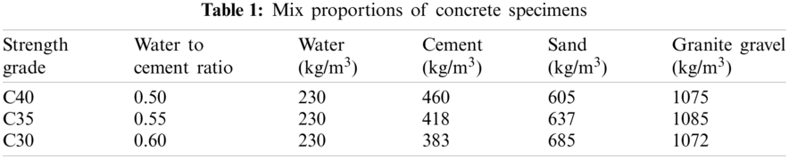
Due to the very slow development process of dissolution, experimental data corresponding to the deterioration of mechanical properties of leached concrete are very limited, especially the seepage dissolution caused by hydraulic water pressure. More seriously, some research results have been characterized by the relationship between mechanical properties and the dissolution time, depth, and area ratio of concrete specimens, which are difficult to be converted into practical engineering applications. The evolution of the compressive and tensile strengths of fly ash-added concrete with respect to the cumulative relative leached calcium, obtained by Li et al. [13], is shown in Fig. 1a, in which the strength grade of used concrete specimens is no more than C25. In addition, the maximum dissolution degree in Fig. 1a is only 27%, whereas engineering practice has shown that the dissolution degree of some local areas of concrete dam bodies is significantly greater than this value [4,5]. Therefore, to obtain a more general deterioration rule corresponding to a larger dissolution degree and higher strength grade, concrete specimens of three strength grades, denoted as C40, C35 and C30, are made in this study. Mix proportions are given in Table 1, where the cementitious material is the P. O 42.5 R cement, and a 0.5 mol/L nitric acid solution is used for the accelerated dissolution test. The relationship between the normalized compressive strength and cumulative relative leached calcium, with a maximum dissolution degree of 52.3%, is then obtained and shown in Fig. 1b. It can be jointly concluded from Figs. 1a and 1b that the compressive and tensile strengths of leached concrete both exhibit an exponential decrease with the increasing degree of calcium dissolution. The decay rate in Fig. 1b is obviously faster than that in Fig. 1a, and the reasons can be summarized as follows. The cementitious material of the former is only cement, while the latter is mixed with fly ash. According to the dissolution mechanism of cement-based materials, the large amount of SiO2 in fly ash can effectively reduce the content of solid CH in hardened cement paste, while the decrease in strength caused by calcium dissolution from CH is notably greater than that of the same content from hydrated calcium silicate (C-S-H) [8].
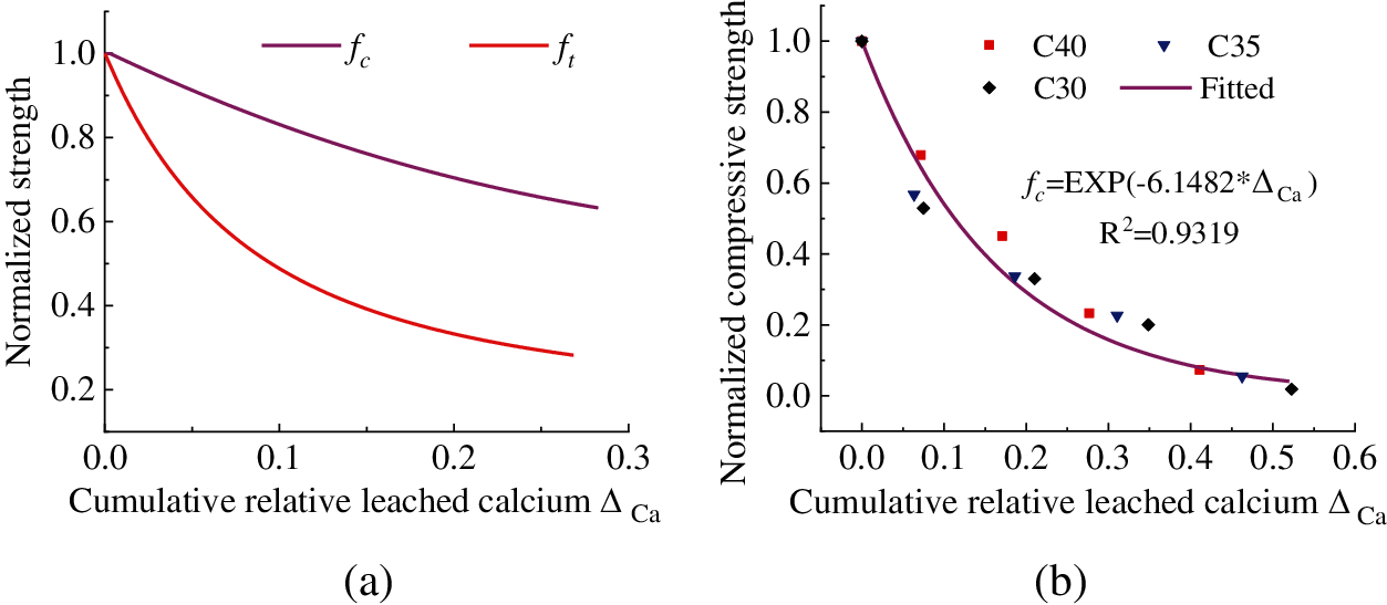
Figure 1: Relationships between concrete strength and the calculative relative leached calcium (fc = compressive strength, ft = tensile strength) (a) Fly ash-added cement concrete (It is a copy version of the original figure in reference [13]) (b) Cement concrete
The elastic modulus is also an important parameter used in the numerical simulation of concrete structures, and experimental results have shown that the evolution law of elastic modulus of leached concrete with respect to the dissolution time or depth is like that of the compressive and tensile strengths [26,27]. Kong et al. [11] carried out seepage dissolution with large-scale hydraulic concrete specimens, and the compressive strength and elastic modulus decreased by 2.24% and 4.10%, respectively, with respect to a calcium dissolution degree of 0.77%. In this study, considering the approximate linear proportional relationship between the elastic modulus and compressive strength of the dam concrete, it is assumed that the evolution law of the elastic modulus with the calculative relative leached calcium is like that of the compressive strength; thus, they can both be represented by an exponential function. According to the proportional relationship, the coefficient of the exponential function used for the elastic modulus can then be inversely calculated. Therefore, the normalized deterioration prediction model of the compressive and tensile strengths and the elastic modulus of hydraulic fly ash-added dam concrete can be established and shown in Fig. 2.
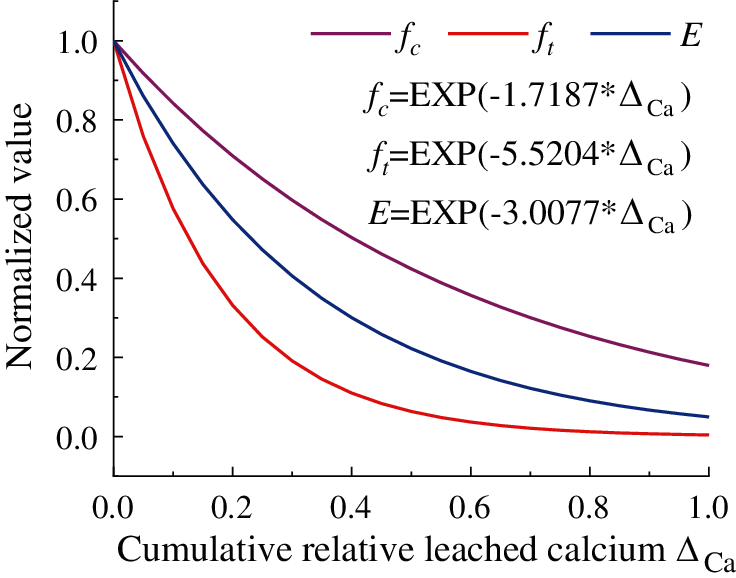
Figure 2: Deterioration models for mechanical properties of the leached concrete (fc = compressive strength, ft = tensile strength, E = elastic modulus, ΔCa = cumulative relative leached calcium)
3 Numerical Simulation of the Seepage Dissolution of Concrete Dams
3.1 Coupled Model of Seepage-Calcium Dissolution-Migration
The seepage dissolution of calcium in concrete dams involves two physical processes: seepage flow and the dissolution-migration of solid calcium. The former obeys Darcy’s law, and in a saturated state, the latter obeys Fick’s diffusion law and the law of conservation for calcium mass. Therefore, the seepage dissolution process can be expressed in a coupled model as follows [28]:
where
To solve the coupled model by numerical simulation, initial and boundary conditions are necessary. For concrete dams, the initial condition and three types of boundary conditions should be defined in the following forms:
(1) Initial condition of the whole dam region:
where
(2) Fixed value boundary:
where
(3) Fixed flux boundary:
where
(4) Permeable layer boundary:
where
3.2 Equilibrium and Nonequilibrium State of Solid-Liquid Calcium
If the pore solution in concrete does not flow, the dissolution rate of solid calcium is generally faster than the diffusion velocity of liquid Ca2+, and it can be considered that there is a thermodynamic equilibrium state between their concentrations, which is usually described by the solid-liquid equilibrium equation [15], as shown in Fig. 3. The dissolution rate of solid calcium can then be converted as follows:
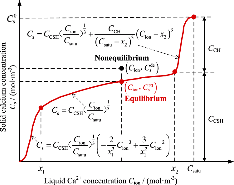
Figure 3: Diagram of the equilibrium and nonequilibrium relationships between solid and liquid calcium concentration (
In the case of a larger seepage velocity, the liquid Ca2+ is quickly carried away by the flowing water, which leads that the newly dissolved solid calcium cannot make up for the lost of Ca2+ in the pore solution, thus it results in an imbalanced relationship between their concentrations. To solve this problem, Gawin et al. [17] described the dissolution rate of solid calcium by chemical potential as follows:
where
3.3 Evolution of the Porosity and Permeability
The dissolution of solid calcium will increase the porosity of concrete, in which the dissolution of CH produces macropores and leads to a significant increase in porosity. Only micropores, which have little effect on the porosity, are formed due to the dissolution of C-S-H [6]. Therefore, to simplify the calculation with high guarantee, the leached C-S-H is generally equivalent to that of solid CH, and the porosity and permeability after dissolution can then be calculated as follows [14]:
where
An RCC gravity dam located in southwest China is taken as an example. It is composed of 17 dam blocks, and the joint width of each dam block is generally 20 m. The maximum dam height is 85 m, and the cross section of the water retaining dam block is shown in Fig. 4. The fortification against earthquake is determined with respect to an exceeding probability of 2% in 100 years, for which the horizontal peak ground acceleration at the surface of the dam foundation is 0.154 g. The seismic dynamic analysis of gravity dams can be conducted for a single dam block, so the water retaining dam block is used in this case. The seepage dissolution-induced spatially non-uniform deterioration of the dam body within 100 years is first simulated, and the seismic response of the deteriorated dam is subsequently analyzed and evaluated according to the current Chinese code of Seismic Design of Hydraulic Structures of Hydropower Project (NB35047-2015) [25].
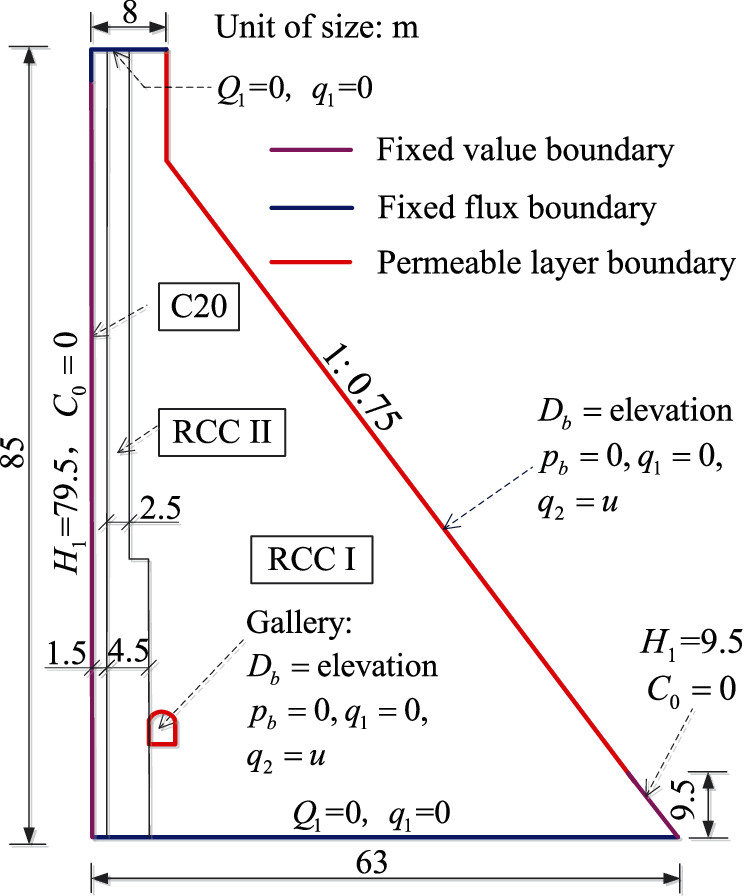
Figure 4: Material zones and seepage dissolution boundaries of the dam body
4.1 Seepage Dissolution Analysis
4.1.1 Calculation Model and Parameters
The coupling simulation of seepage and calcium dissolution-migration is implemented on the COMSOL Multiphysics software platform, where Darcy's law module and the convection-diffusion equation module are jointly used. Due to the large volume of a concrete dam and the significant difference of seepage velocity in different dam regions, it is difficult to strictly distinguish whether the solid-liquid calcium concentration of the concrete inside the dam body is in an equilibrium state. To solve this problem, numerical simulations under the equilibrium and nonequilibrium states are both conducted in the first step. The calcium dissolution degree of each part of the dam body is then determined as the larger value of these two.
For the stable seepage field without external source term in this paper, the two parameters
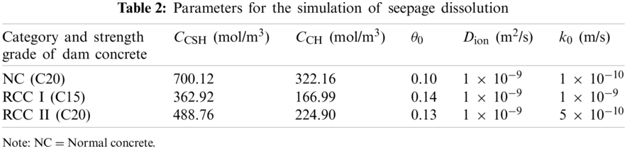
The distributions of seepage pressure and flow line in the dam body are shown in Fig. 5. As seen in the figure, the distribution laws before and after 100 years of seepage dissolution are basically the same. The anti-seepage measure of the normal concrete layer on the upstream surface of the dam body, the thickness of which is 1.5 m, has obviously reduced the elevation of the saturation line in the dam body. A large amount of seepage water seeps out from the surroundings of the gallery, especially the vault and downstream wall, and this phenomenon is consistent with the observed distribution law of most concrete dams, such as the Shimantan RCC gravity dam [19]. Due to the increase in concrete permeability caused by the dissolution of solid calcium, the elevation of the saturation line in dam body significantly rises, with a maximum distance of 1.3 m and an increase ratio of 3.1%.
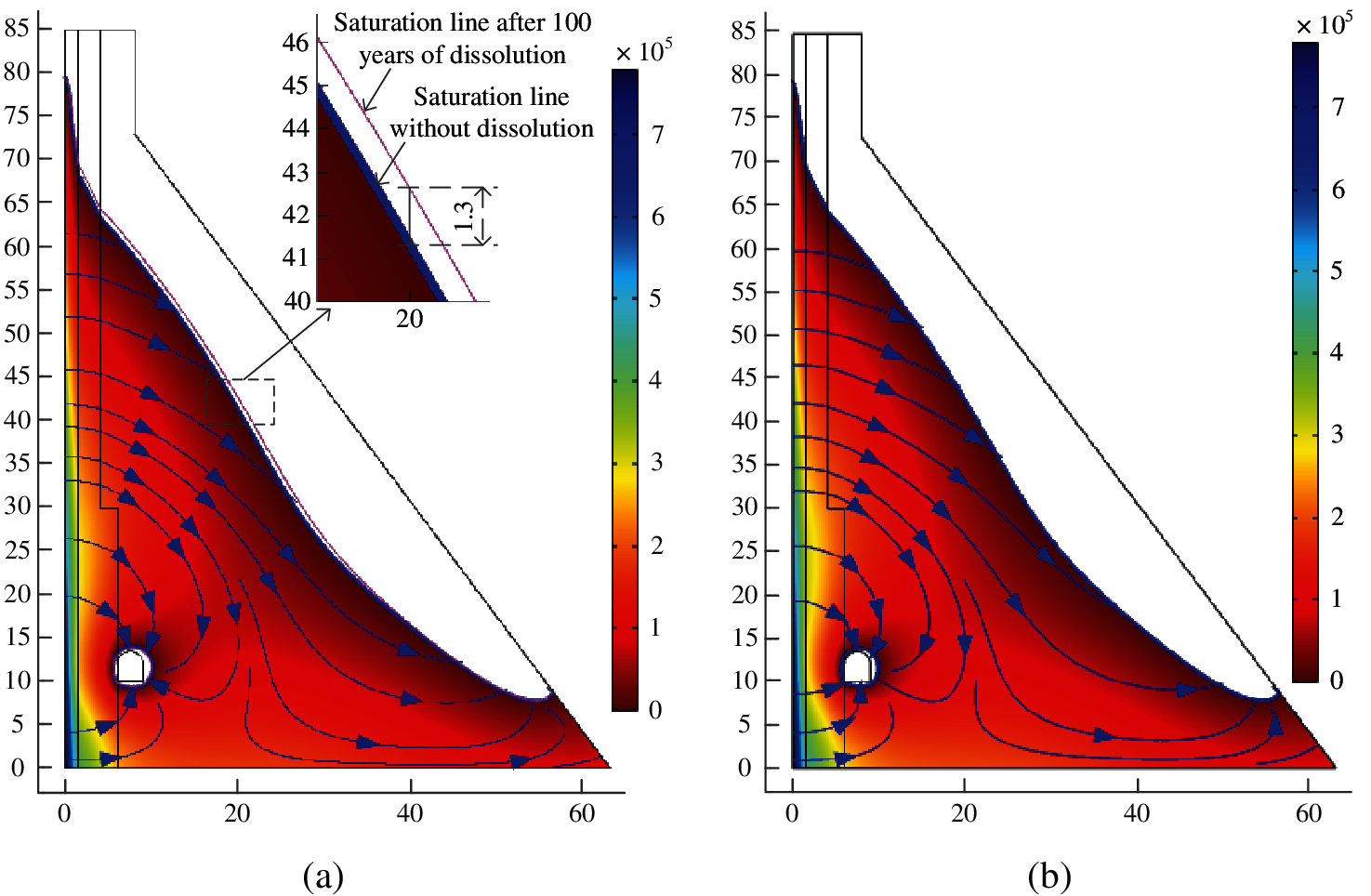
Figure 5: Distributions of seepage pressure (Unit: Pa) and flow line in the dam body (a) Unleached (b) Leached for 100 years
Under the equilibrium and nonequilibrium calculation modes, distributions of the solid calcium dissolution in the dam body after 100 years of seepage dissolution are shown in Fig. 6. As seen in Fig. 6a, in the equilibrium state, the main leached areas are the upstream surface of the dam body, dam toe and gallery wall, with a dissolution depth of 4.0, 5.0 and 1.0 m, respectively, and there is no calcium dissolution in the dam region within the dissolution front. From the surface to the dissolution front, the distribution of remaining solid calcium concentration is consistent with the solid-liquid equilibrium equation; thus, the concentration gradient in the dissolution region is very large. Fig. 6b shows that calcium dissolution occurs in all areas of the dam body when the nonequilibrium state is used. Except for the upstream surface and dam toe, the leached solid calcium in most areas of the dam body is approximately 1 mol/m3 and is almost linearly developed, as shown in Fig. 7. Therefore, the dissolution degree decreases with the initial content of solid calcium in concrete. For RCC I, which occupies the largest volume proportion of the dam body and has the lowest initial calcium content, the dissolution degree is 0.19% within 100 years. According to the deterioration models for mechanical properties of leached concrete shown in Fig. 2, the compressive strength, tensile strength, and elastic modulus will be reduced by 0.32%, 1.04% and 0.57%, respectively, which do not exceed the maximum allowable deviation of 5% for hydraulic engineering. Therefore, the influence of seepage dissolution on the mechanical properties of concrete inside the dam body is relatively small and can be ignored in simplified analysis. The above differences between the two calculation modes can be interpreted as follows. According to the solid-liquid equilibrium theory, the dissolution rate of solid calcium is much faster than the migration velocity of liquid Ca2+, so the migrated liquid Ca2+ can be made up in a timely manner, and its concentration in the area behind the dissolution front is always in the saturation state. However, for the nonequilibrium state, the dissolution rate of the solid calcium is determined by the solid calcium concentration distance between the actual and balanced values, and the migration velocity of liquid Ca2+ is significantly accelerated by the seepage flow, so the dissolved solid calcium cannot saturate the concentration of liquid Ca2+, which finally leads to the larger dissolution areas of the dam body.
Figure 6: Dissolution state of the dam body subjected to 100 years of seepage dissolution (Unit: mol/m3) (a) Dissolution region of Cs in the equilibrium state (b) Dissolution amount of Cs in the non-equilibrium state
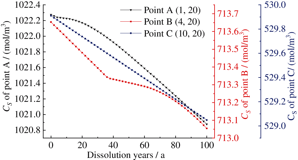
Figure 7: Evolution of solid calcium concentration in the dam body with dissolution time under the nonequilibrium state (The numbers in parentheses are coordinates, and the three points are in concrete zones of the NC, RCC II and RCC I, respectively)
Overall, it can be concluded that there are notable differences between the results of the two calculation modes, in which the equilibrium theory-based dissolution area is very concentrated on boundaries with a higher dissolution degree, while all areas of the dam body are leached to a slight degree for the nonequilibrium theory. In this study, to consider the influence of the uncertainty of the equilibrium or nonequilibrium state of solid-liquid calcium concentration anywhere, the dissolution degree of each part of the dam body is taken as the larger value of these two calculation modes. Furthermore, according to the simulation results shown in Fig. 6, the overall dissolution degree of this dam after 100 years is approximately 2%. The observation results of some concrete dams reveal that the seepage dissolution seriously occurs through cracks. Such as an RCC gravity dam in China, which was built in 1993 and had many penetrating cracks in the dam body, according to the measured amount of leached Ca2+ in 2003, the overall dissolution degree after 100 years was estimated to be 13.6% [23]. Therefore, for these concrete dams, the seepage dissolution in concrete cracks should be specially considered according to their location, direction and opening, and this will be a key research focus for the ageing of concrete dams in the future.
According to the Chinese code of Seismic Design of Hydraulic Structures of Hydropower project (NB35047-2015) [25], the mass of a near-field foundation and the radiation damping effect of a far-field foundation should be considered in the seismic safety evaluation of concrete dams whose seismic fortification category is Class A. The key issue involved in this requirement is to eliminate the reflection of scattered waves to achieve the propagation of waves from the calculation domain to the far-field infinite domain [24]. The seismic fortification category of the analyzed dam is also in Class A. To solve this problem, the concentrated viscoelastic artificial boundary is used in this study to achieve the above requirements, by which spring damper elements are attached on the intercepted artificial boundary, and the detailed steps and methods have already been discussed in our previous study [2]. Furthermore, static loads should also be considered, which leads to the spring damper elements being deformed before simulating the earthquake load; thus, the induced deformation should be eliminated. To achieve this goal, static analysis can be implemented in the first step, and the node reaction at the fixed end of each spring damper element can be extracted. Loading all the static loads in the initial state, nonlinear dynamic analysis is then conducted under seismic time history excitation, during which the node reaction obtained in the first step is superimposed with the equivalent node load of the seismic wave and is then applied to the artificial boundary node.
4.2.1 Calculation Model and Parameters
Taking the heel and toe of the dam body as reference points, the simulation ranges of the dam foundation in the upstream, downstream, and vertical directions are all determined to be 2 times the dam height. According to the simulation results discussed in Section 4.1.2, the dissolution degree at the surface of the leached areas changes sharply, as shown in Fig. 6a. Therefore, these areas are divided into fine meshes with a length of no more than 0.2 m, and the meshes are then gradually changed to large size used inside the dam body and the dam foundation. The finite element model is shown in Fig. 8.
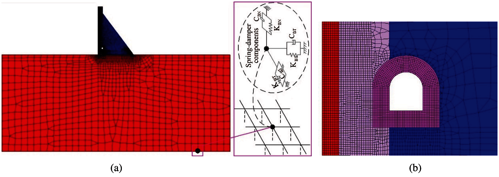
Figure 8: Finite element model (a) Complete model with the concentrated viscoelastic artificial boundary (b) Details of the upstream surface and gallery
The static loads include the self-weight of the dam body, the static water pressure corresponding to the normal water level of the upstream and downstream reservoirs, the wave pressure, and the sediment pressure (the design sedimentation depth is 41.84 m within 100 years). According to the Chinese code of NB35047-2015 [25], horizontal and vertical seismic actions should be considered at the same time, in which the peak acceleration in the vertical direction is generally taken as 2/3 of the horizontal design value, and for concrete gravity dams, horizontal seismic action only needs to be considered along the river direction. The seismic action contains the hydrodynamic pressure and inertial force, of which the former is frequently conducted by the additional mass method proposed by Westergard [2], and the latter is converted into the equivalent nodal load when using the viscoelastic artificial boundary. Time series of acceleration of the design seismic wave in the horizontal direction is shown in Fig. 9.
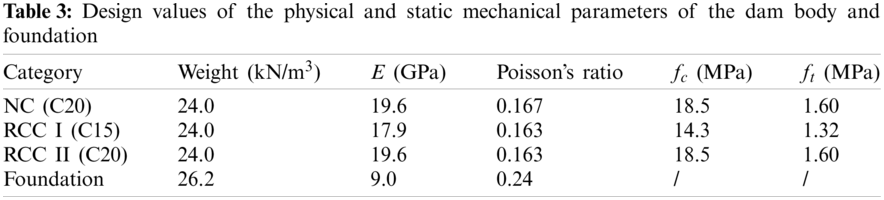
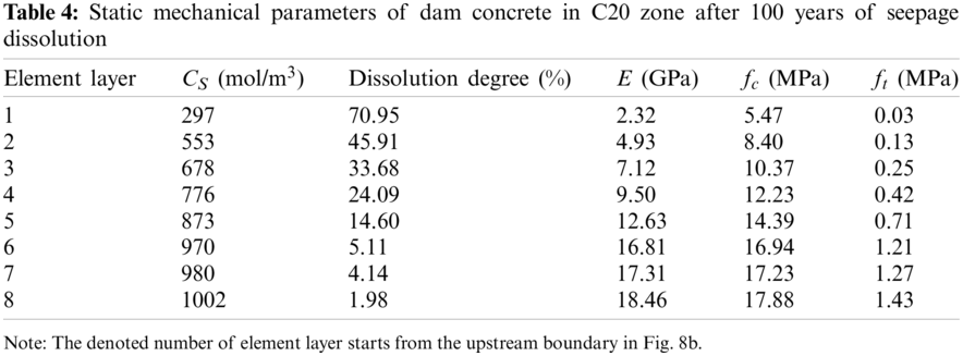
The design values of the physical and static mechanical parameters of the dam body and foundation are given in Table 3. The mechanical parameters of leached concrete at each part of the dam body are determined according to the remaining concentration of solid calcium and the deterioration model shown in Fig. 2. Taking the C20 normal concrete layer as an example, which has a thickness of 1.5 m and is poured on the upstream surface of the dam body, the static mechanical parameters after 100 years of seepage dissolution are given in Table 4. The dynamic values of the strength and elastic modulus of concrete are 20% and 50% higher than the static values, respectively [25].
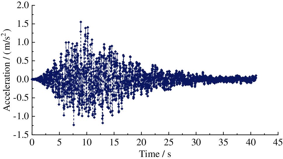
Figure 9: Time series of acceleration of the design seismic wave
When suffering an earthquake, it is inevitable that the concrete of the dam body will be cracked or damaged, especially old dams. Therefore, to accurately obtain the seismic dynamic response of concrete dams, it is very important to reasonably characterize the mechanical behaviour of the dam concrete. The smeared crack model, as shown in Fig. 10, disperses the actual crack into the whole element without characterizing its position and direction in advance [29]. It is only necessary to treat the material as anisotropic when the maximum principal stress at the integration point exceeds the cracking stress, and the induced mechanical property degradation is then realized by adjusting the constitutive relationship. The smeared crack model is used in this study to simulate the nonlinear fracture of dam concrete under earthquake action, and the dissolution-induced deterioration of concrete is determined as the initial condition before an earthquake. Furthermore, to avoid the sensitivity of element size in the FEM simulation, the ultimate strain (
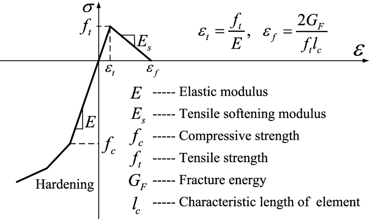
Figure 10: Uniaxial stress-strain curve of concrete based on the smeared crack model
In case of the fortification against earthquake, the horizontal displacement of the dam crest along the river direction is shown in Fig. 11, where a positive value means the displacement towards the downstream direction. As seen in the figure, the vibration law of the dam crest is basically the same for the conditions before and after 100 years of seepage dissolution. However, the fluctuation amplitude and convergence value of the dam crest displacement increase obviously in the later condition, in which the convergence value is the displacement under the combination of all static loads. The maximum displacements towards the upstream and downstream directions are −6.56 and 24.30 mm, −9.86 and 27.75 mm, and the convergence displacements are 8.57 and 9.16 mm, respectively, which shows an increase ratio of 6.9% and 21.9% for the static and dynamic displacements at the dam crest.
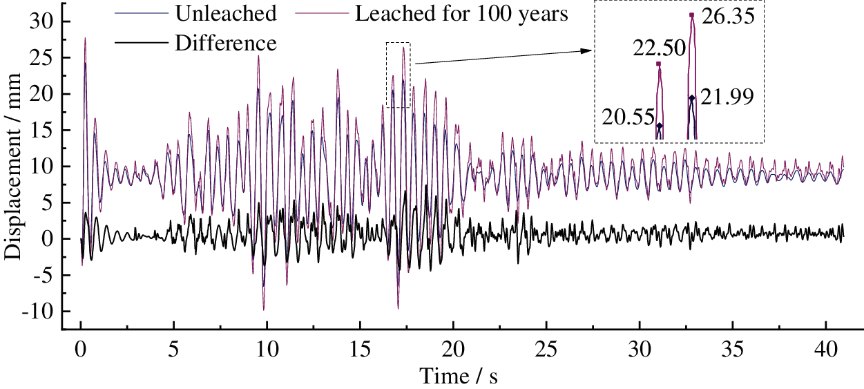
Figure 11: Time series of the horizontal displacement of the dam crest along the river direction (Difference is the displacement difference between the two conditions)
4.2.3 Seismic Cracking of Dam Body
The failure mode of the dam body, which can be represented by the distribution of equivalent cracking strain-based cracking areas [30,31], is shown in Fig. 12. As seen in the figure, for the unleached condition, only a small cracking area intensively appears in the dam heel, and the cracking depth does not exceed the centreline of the dam foundation curtain, which confirms the good design compliance of this dam to the requirements of the Chinese seismic design code for concrete gravity dams. Subjected to 100 years of seepage dissolution, due to the serious deterioration on the upstream surface of the dam body and the inherent stress concentration effect on the crest of gravity dams [32], the seismic cracking area first appears on the upstream surface of the dam body at the elevation with respect to the break point of the downstream slope, and it rapidly expands to the dam crest and the low elevation, which ends at 1/4 of the dam height above the foundation plane. The cracking area also intensively extends to the inside of the dam body between elevations of 2/3 and 1/2 of the dam height above the foundation plane, with a cracking depth of 5.8 m and a cracking angle of approximately π/4 with respect to the horizontal direction. The cracking depth of the upper 1/3 of the dam height is approximately 1.5 m, which indicates that the normal concrete impervious layer on the upstream surface of the dam body is completely cracked and fails.
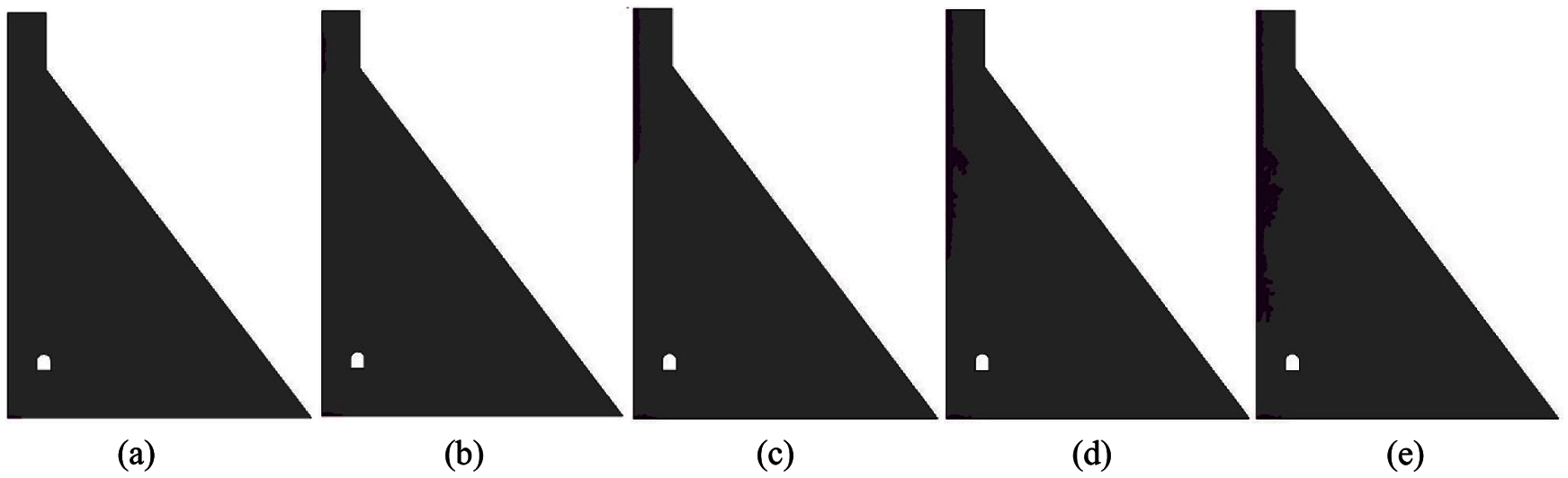
Figure 12: Sketch map of equivalent cracking areas of the dam body under the design earthquake (a) Leached for 0 year, t = 40.96 s (b) Leached for 100 years, t = 0.8 s (c) Leached for 100 years, t = 9.8 s (d) Leached for 100 years, t = 20 s (e) Leached for 100 years, t = 40.96 s
4.2.4 Principal Stress of Dam Body
The distributions of envelope values of the maximum and minimum principal stresses under the design earthquake are shown in Figs. 13 and 14, respectively. After eliminating the influence of the stress concentration phenomenon in the finite element method, the dynamic tensile and compressive stresses of the dam body in the no dissolution state are both small and do not exceed the strength design value, of which the maximum stresses are approximately 1.5 and 3.5 MPa, respectively. After 100 years of seepage dissolution, the stress in the cracking area of the upstream surface of the dam body, with respect to Fig. 12e, is very large and has exceeded the current strength of leached concrete, so it is finally in a state of cracking failure, which also leads to a significant increase in the tensile stress near the breakpoint of the downstream slope of the dam body. If the earthquake intensity further increases, the cracking area will connect at this elevation from the upstream to downstream side. Furthermore, due to the softening effect of dam concrete caused by seepage dissolution, the stress concentration areas at the dam heel and toe both move to the interior of the dam body. Seepage dissolution has no obvious effect on the tensile stress around the gallery, as shown in Fig. 15, but it is also very dangerous, especially the top arch and the upstream sidewall, where the maximum tensile stress is close to 1.0 MPa, and thus, these areas are weak in resistance against earthquakes. Overall, although large-scale cracking areas are formed on the upstream surface of the leached dam body under the design earthquake, the large volume of a concrete gravity dam can still ensure that the stress status of the remaining dam body does not change significantly and is in a controllable state.
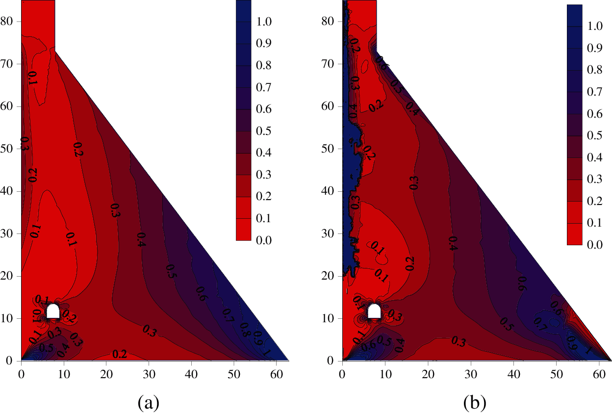
Figure 13: Envelop diagram of the maximum principal stress of the dam body (a) Unleached (b) Leached for 100 years
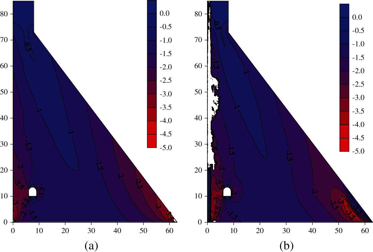
Figure 14: Envelop diagram of the minimum principal stress of the dam body (a) Unleached (b) Leached for 100 years
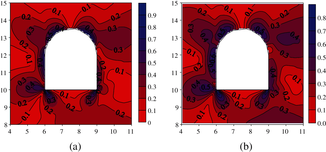
Figure 15: Envelop diagram of the maximum principal stress around the gallery (a) Unleached (b) Leached for 100 years
According to the Chinese code of NB35047-2015, the strength of a hydraulic structure under the most unfavorable load combination should meet the ultimate state of bearing capacity, which is defined as follows [25]:
where
According to the maximum dissolution degree at each part of the dam body, as shown in Fig. 6, the remaining tensile and compressive strength of the leached dam concrete can be predicted by the deterioration models shown in Fig. 2. The envelope values of principal stress are then used to conduct the strength check, and the failure areas of the dam body are shown in Fig. 16, where the failure of tensile strength accounts for almost all the proportion. As seen in the figure, the strength failure area is only a small part at the dam toe for the unleached condition, while it is widely distributed for the deteriorated dam subjected to 100 years of seepage dissolution. The failure area of tensile strength increases sharply at the dam toe, with a depth and height of approximately 5.0 and 11.0 m, respectively. The failure range of the dam heel is within 4.0 m from the upstream surface, which has not yet reached the centreline of the dam foundation grouting curtain. However, the depth of the strength failure area on the upstream surface of the upper dam body is more than 4 m; thus, it has exceeded the impervious layer of this RCC dam, which is composed of the normal concrete and RCC II layers, with a thickness of 1.5 and 2.5 m, respectively. For long-term leached concrete dams encountering a design earthquake, the widely distributed potential cracking area does not satisfy the seismic requirements in the Chinese code of NB35047-2015, and the anti-seepage system of the RCC gravity dams will be seriously damaged. Therefore, the upstream surface of concrete dams subjected to the long-term deterioration of seepage dissolution should be strengthened to improve the seismic resistance.
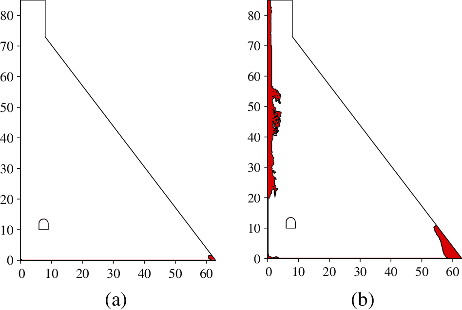
Figure 16: Strength failure areas of the dam body under the design earthquake (a) Unleached (b) Leached for 100 years
To quantify the influence of seepage dissolution on the seismic performance of concrete dams, laboratory tests of concrete specimens and numerical simulation of concrete dams are connected by using the cumulative relative leached calcium as the aging index, and deterioration models are established to predict the mechanical properties of leached concrete. The seepage dissolution-induced spatially non-uniform deterioration of a concrete dam is modelled, and the seismic response of the deteriorated dam is subsequently analyzed and evaluated according to the current Chinese code of NB35047-2015. The following conclusions can be drawn:
1. For the two calculation modes with equilibrium and non-equilibrium states of the solid-liquid calcium concentration, the seepage dissolutions of a concrete dam both develop from the surface to the inside of the dam body, and the main dissolution areas are the upstream surface of the dam body, dam toe and gallery wall. In the equilibrium state, the dissolution degree of the above regions is obviously greater than that in the nonequilibrium state, with a value of 1.98% at a depth of 1.5 m from the upstream surface. However, the dissolution area obtained by the nonequilibrium state is obviously larger. All areas inside the dam body also suffer a slight degree of calcium dissolution, as in the case of the C15 RCC of the analyzed concrete dam, whose dissolution degree is 0.19% within 100 years.
2. Seepage dissolution will lead to a rise in the saturation line, with an increased ratio of 3.1% within 100 years. For the design earthquake coupled with 100 years of seepage dissolution, the static and dynamic displacements of the dam crest along with the river direction increase by 6.9% and 21.9%, respectively, and a large range of strength failure areas, mainly distributed at the dam toe and the upstream surface of the dam body where the relative elevation is higher than 1/4 the dam height, are newly formed with cracking depths of 5.0 and 4.0 m, respectively. Therefore, the anti-seepage system of the RCC dam will be destroyed, and seismic reinforcements need to be conducted for these concrete dams subjected to the long-term deterioration of seepage dissolution.
Funding Statement: This work was supported by the National Natural Science Foundation of China (Grant Nos. 51709021, 52079120), the project funded by China Postdoctoral Science Foundation (Grant No. 2020M670387), the Belt and Road Special Foundation of the State Key Laboratory of Hydrology-Water Resources and Hydraulic Engineering (Grant No. 2019nkzd03).
Conflicts of Interest: The authors declare that they have no conflicts of interest to report regarding the present study.
1. Abdulrazeg, A. A., Noorzaei, J., Khanehzaei, P., Jaafar, M. S., Mohammed, T. A. (2010). Effect of temperature and creep on roller compacted concrete dam during the construction stages. Computer Modeling in Engineering & Sciences, 68(3), 239–268. DOI 10.3970/cmes.2010.068.239. [Google Scholar] [CrossRef]
2. Gu, C., Wang, S., Bao, T. (2015). Influence of construction interfaces on dynamic characteristics of roller compacted concrete dams. Journal of Central South University, 22(4), 1521–1535. DOI 10.1007/s11771-015-2669-5. [Google Scholar] [CrossRef]
3. Zhao, E., Wu, C., Wang, S., Hu, J., Wang, W. (2020). Seepage dissolution effect prediction on aging deformation of concrete dams by coupled chemo-mechanical model. Construction and Building Materials, 237(2), 117603. DOI 10.1016/j.conbuildmat.2019.117603. [Google Scholar] [CrossRef]
4. Zhu, B. (2012). On the expected life span of concrete dams and the possibility of endlessly long life of solid concrete dams. Journal of Hydraulic Engineering, 43(1), 1–9. DOI 10.13243/j.cnki.slxb.2012.01.012. [Google Scholar] [CrossRef]
5. Hu, J., Ma, F., Li, Z., Huo, J. (2017). Review of spatial variability of mechanical properties of concrete dams impacted by seepage dissolution. Advances in Science and Technology of Water Resources, 37(4), 87–94. DOI 10.3880/j.issn.1006-7647.2017.04.015. [Google Scholar] [CrossRef]
6. Carde, C., François, R. (1997). Effect of the leaching of calcium hydroxide from cement paste on mechanical and physical properties. Cement and Concrete Research, 27(4), 539–550. DOI 10.1016/S0008-8846(97)00042-2. [Google Scholar] [CrossRef]
7. Rozière, E., Loukili, A. (2011). Performance-based assessment of concrete resistance to leaching. Cement and Concrete Composites, 33(4), 451–456. DOI 10.1016/j.cemconcomp.2011.02.002. [Google Scholar] [CrossRef]
8. Arribas, I., Vegas, I., García, V., Vigil de la Villa, R., Martínez-Ramírez, S. et al. (2018). The deterioration and environmental impact of binary cements containing thermally activated coal mining waste due to calcium leaching. Journal of Cleaner Production, 183(1), 887–897. DOI 10.1016/j.jclepro.2018.02.127. [Google Scholar] [CrossRef]
9. Jebli, M., Jamin, F., Pelissou, C., Malachanne, E., Garcia-Diaz, E. et al. (2018). Leaching effect on mechanical properties of cement-aggregate interface. Cement and Concrete Composites, 87, 10–19. DOI 10.1016/j.cemconcomp.2017.11.018. [Google Scholar] [CrossRef]
10. Su, H., Hu, J., Li, H. (2018). Multi-scale performance simulation and effect analysis for hydraulic concrete submitted to leaching and frost. Engineering with Computers, 34(4), 821–842. DOI 10.1007/s00366-018-0575-9. [Google Scholar] [CrossRef]
11. Kong, X., Ji, G., Liu, Y., Liu, C. (2012). Research on seepage dissolution of hydraulic concrete. Journal of China Institute of Water Resources and Hydropower Research, 10(1), 63–68. DOI 10.3969/j.issn.1672-3031.2012.01.011. [Google Scholar] [CrossRef]
12. Lin, W., Cheng, A., Huang, R., Chen, C., Zhou, X. (2011). Effect of calcium leaching on the properties of cement-based composites. Journal of Wuhan University of Technology-Materials Science Edition, 26(5), 990–997. DOI 10.1007/s11595-011-0350-x. [Google Scholar] [CrossRef]
13. Li, J., Cao, J., Lin, L., Tian, J., Wang, A. et al. (2001). New development of the study on hydraulic concrete durability. Water Power, 27(4), 44–47. DOI 10.3969/j.issn.0559-9342.2001.04.013. [Google Scholar] [CrossRef]
14. Kenichiro, N., Tetsuya, I., Koichi, M. (2006). Modeling of calcium leaching from cement hydrates coupled with micro-pore formation. Journal of Advanced Concrete Technology, 4(3), 395–407. DOI 10.3151/jact.4.395. [Google Scholar] [CrossRef]
15. Wan, K., Li, Y., Sun, W. (2013). Experimental and modelling research of the accelerated calcium leaching of cement paste in ammonium nitrate solution. Construction and Building Materials, 40, 832–846. DOI 10.1016/j.conbuildmat.2012.11.066. [Google Scholar] [CrossRef]
16. Wang, H., Guo, C., Zou, D., Sun, X. (2018). Modelling of calcium leaching of concrete subjected to aggressive water. Advances in Science and Technology of Water Resources, 38(3), 26–31. DOI 10.3880/j.issn.1006-7647.2018.03.005. [Google Scholar] [CrossRef]
17. Gawin, D., Pesavento, F., Schrefler, B. A. (2008). Modeling of cementitious materials exposed to isothermal calcium leaching considering process kinetics and advective water flow. Part 1: Theoretical model. International Journal of Solids and Structures, 45(25–26), 622l–6240. DOI 10.1016/j.ijsolstr.2008.07.010. [Google Scholar] [CrossRef]
18. Huo, J., Ma, F., Ji, X. (2019). Porosity and permeability variations of a dam curtain during dissolution. Water Science and Engineering, 12(2), 155–161. DOI 10.1016/j.wse.2019.05.007. [Google Scholar] [CrossRef]
19. Zhang, K., Shen, Z., Xu, L. (2020). Durability control index of anti-seepage curtain considering the effect of advection-diffusion-driven leaching. Journal of Hydraulic Engineering, 51(2), 169–179. DOI SLXB.0.2020-02-005. [Google Scholar]
20. Rikard, H., Richard, M., Anders, A. (2021). Performance of data-based models for early detection of damage in concrete dams. Structure and Infrastructure Engineering, 17(2), 275–289. DOI 10.1080/15732479.2020.1737146. [Google Scholar] [CrossRef]
21. Campos, A., López, C. M., Blanco, A., Aguado, A. (2016). Structural diagnosis of a concrete dam with cracking and high nonrecoverable displacements. Journal of Performance of Constructed Facilities, 30(5), 1–12. DOI 10.1061/(ASCE)CF.1943-5509.0000869. [Google Scholar] [CrossRef]
22. Pan, J., Xu, Y., Jin, F., Zhang, C. (2014). A unified approach for long-term behavior and seismic response of AAR-affected concrete dams. Soil Dynamics and Earthquake Engineering, 63, 193–202. DOI 10.1016/j.soildyn.2014.03.018. [Google Scholar] [CrossRef]
23. Wang, S., Bao, T. (2020). Numerical analysis on influence of seepage dissolution on long-term deformation of high concrete dam. Journal of Yangtze River Scientific Research Institute, 37(6), 62–69. DOI 10.11988/ckyyb.20190266. [Google Scholar] [CrossRef]
24. Xu, Q., Zhang, T., Chen, J., Li, J., Li, C. (2021). The influence of reinforcement strengthening on seismic response and index correlation for high arch dams by endurance time analysis method. Structures, 32(3), 355–379. DOI 10.1016/j.istruc.2021.03.007. [Google Scholar] [CrossRef]
25. NB35047-2015 (2015). Chinese code for seismic design of hydraulic structures of hydropower project. http://std.samr.gov.cn/hb/search/stdHBDetailed?id=8B1827F2334CBB19E05397BE0A0AB44A. [Google Scholar]
26. Huang, B., Qian, C. (2011). Characterization and stress-strain relationship of leached concrete. Journal of the Chinese Ceramic Society, 39(1), 87–91. DOI 10.14062/j.issn.0454-5648.2011.01.031. [Google Scholar] [CrossRef]
27. Zhou, X., Ye, L., Zheng, J. (2016). An experimental study on the degradation of mechanical properties of leached concrete. Journal of Zhejiang University of Technology, 44(5), 524–528. DOI 10.3969/j.issn.1006-4303.2016.05.011. [Google Scholar] [CrossRef]
28. Jia, P., She, C. (2019). Finite element modeling of seepage dissolution of cement-based materials. Journal of Yangtze River Scientific Research Institute, 36(5), 108–115. DOI 10.11988/ckyyb.20180173. [Google Scholar] [CrossRef]
29. Jiang, J., Lu, X. (2015). Finite element analysis of concrete structures (Second edition). Beijing: Tsinghua university press. [Google Scholar]
30. Mohammad, A., Mohsen, G. (2016). Seismic performance evaluation of a jointed arch dam. Structure and Infrastructure Engineering, 12(2), 256–274. DOI 10.1080/15732479.2015.1009124. [Google Scholar] [CrossRef]
31. Tong, Q., Ren, Q., Shen, L., Zhang, L., Yang, Y. (2018). Safety evaluation of concrete structures based on a novel energy criterion. Computer Modeling in Engineering & Sciences, 114(1), 33–58. DOI 10.3970/cmes.2018.114.033. [Google Scholar] [CrossRef]
32. Hariri-Ardebili, M. A., Saouma, V. (2015). Quantitative failure metric for gravity dams. Earthquake Engineering & Structural Dynamics, 44(3), 461–480. DOI 10.1002/eqe.2481. [Google Scholar] [CrossRef]
 | This work is licensed under a Creative Commons Attribution 4.0 International License, which permits unrestricted use, distribution, and reproduction in any medium, provided the original work is properly cited. |