| Computer Modeling in Engineering & Sciences |
DOI: 10.32604/cmes.2022.019214
ARTICLE
Strategy for Creating AR Applications in Static and Dynamic Environments Using SLAM- and Marker Detector-Based Tracking
1Electronics and Telecommunications Research Institute, Daejeon, 34129, Korea
2Graduate School of Engineering, The University of Tokyo, Tokyo, 113-0033, Japan
3School of Computer Science and The Research Institute of Natural Science, Gyeongsang National University, Jinju-si, 52828, Korea
*Corresponding Author: Suwon Lee. Email: leesuwon@gnu.ac.kr
Received: 09 September 2021; Accepted: 26 October 2021
Abstract: Recently, simultaneous localization and mapping (SLAM) has received considerable attention in augmented reality (AR) libraries and applications. Although the assumption of scene rigidity is common in most visual SLAMs, this assumption limits the possibilities of AR applications in various real-world environments. In this paper, we propose a new tracking system that integrates SLAM with a marker detection module for real-time AR applications in static and dynamic environments. Because the proposed system assumes that the marker is movable, SLAM performs tracking and mapping of the static scene except for the marker, and the marker detector estimates the 3-dimensional pose of the marker attached to the dynamic object. We can place SLAM maps, cameras, and dynamic objects (markers) on the same coordinate system, and we can also accurately augment AR resources in real-time on both the static scene and dynamic objects simultaneously. Additionally, having a static map of the scene in advance has the advantage of being able to perform tracking of static and dynamic environments with mapping disabled. In this paper, we evaluate whether the proposed tracking system is suitable for AR applications and describe a strategy for creating AR applications in static and dynamic environments with a demonstration.
Keywords: Augmented reality; SLAM; marker; tracking; coordinate system
Augmented reality (AR) is a technology that overlays a virtual object on a real scene to allow viewers to interact with the surrounding environment in real-time; it is used in various fields, including education and entertainment. Tracking is an important process and a popular research topic in AR to understand the relationship between the surrounding environment and the user (camera) perspective. Among the types of tracking, simultaneous localization, and mapping (SLAM) creates a map of the surrounding environment while navigating within it. Most visual SLAMs consist of two basic processes: tracking and mapping. In the field of AR, visual SLAM has the following advantages. First, although square marker-based tracking [1] is performed only in a limited area, SLAM-based tracking enables accurate pose estimation and map generation in complex and large-scale environments. Second, by referring to the SLAM-based map, camera localization can be performed [2] in the surrounding environment so that the virtual object is precisely registered in advance using the map [3,4], or it can allow user interaction for AR applications [5].
Oriented features from accelerated segment test (FAST) and rotated binary robust independent elementary features (BRIEF) (ORB)-SLAM2 [6,7] and visual-inertial SLAM (VINS) [8], which are representative visual SLAM algorithms, operate in real-time and are suitable for AR applications. However, in most SLAM systems [3,6–8], it is common to assume that the environment is stationary and ignore the moving object as an outlier. Therefore, if there are many moving objects in the camera view, tracking of the static scene fails, and it is difficult to create an accurate map.
Generally, the problem of visual SLAM that considers static and dynamic environments simultaneously consists of two parts: a technique for creating a map of the static environment while removing the dynamic elements as outliers, and another to simultaneously track static and dynamic environments [9]. Researches [10,11] has been proposed to track static scenes and moving objects by adding an instance-level object detection module to the visual SLAM module, but SLAM-based AR applications in dynamic environments remain challenging.
Hence, to create SLAM-based AR applications that consider both static and dynamic environments simultaneously, the following issues should be considered:
- Accurately track the static environment and multiple moving objects at the same time;
- Each dynamic component must be classified; and
- Real-time SLAM-based AR applications should be configured with a lightweight tracking algorithm and should work on mobile devices.
To resolve the above-mentioned issues, we propose a strategy for creating AR applications using SLAM and marker detector-based tracking in static and dynamic environments. Compared with existing studies [10,11] that combine deep-learning-based detection algorithms with SLAM (or visual odometry), our system can accurately augment virtual objects by tracking the reference position of dynamic environments. It also provides real-time AR applications using a lightweight tracking algorithm. In summary, the main contributions of our study are as follows:
1. Static and dynamic environments (attached with markers) are prepared for an AR application in advance, the SLAM module added marker masking accurately tracks only the static environment, and the marker detector module recognizes markers and tracks 3-dimensional (3D) pose of the dynamic environment;
2. After the process of (1), the pose of the dynamic environment in the marker coordinate system is transformed into the SLAM coordinate system for each frame, and different virtual objects are registered in static and dynamic environments simultaneously in real-time;
3. Identification by marker patterns enables the efficient management of each dynamic element for AR applications and provides different interactions for each dynamic element; and
4. By creating a SLAM map of the static environment in advance, AR resources are deployed in both static and dynamic environments, and we use SLAM- and marker detector-based tracking with the mapping process turned off.
The remainder of this paper is organized as follows. Section 2 describes extant research related to our system. Section 3 provides the details of our tracking proposal, and Section 4 evaluates the tracking system. Section 5 discusses the strategy for creating AR applications, and Section 6 presents the conclusions of this study.
The most important problem for realizing AR is pose estimation between the camera and world coordinate system [12]. Until the early 2000s, vision-based AR was mainly used to register virtual objects through marker-based tracking [1,13]. The marker detector recognizes a regular pattern of square markers without a separate learning process and estimates the camera pose based on the four corner positions in the marker coordinate system. Although the marker simplifies the tracking task and enables fast and accurate pose estimation, it is difficult to apply if the marker cannot be installed in advance, or if the tracking target is large and complex.
Markerless tracking methods have been proposed based on their ability to match naturally existing features. First, references [14–16] recognize objects of interest in the surrounding environment and track their features. Although this approach can increase the reliability of a pose based on a prefabricated 3D model, it is inconvenient to prepare a model of an object to be recognized in advance. Next, structure-from-motion and keyframe-based SLAM were introduced sequentially; specifically, SLAM generates a 3D map of an unknown environment while simultaneously recovering the trajectory of the camera. SLAM systems began to show performance applicable to AR starting with monocular SLAM studies [3,17]. Recently, SLAM systems, such as ORB-SLAM2 [6,7] and VINS [8], which can perform real-time camera localization and simultaneous environment mapping, have appeared. However, conventional SLAM systems are designed to create a map of the static scene while considering dynamic elements as outliers, making them unsuitable for simultaneous tracking of static and dynamic environments. Meanwhile, homography-based pose estimation [18,19] and template-based motion estimation [20,21] methods can be performed to recognize an arbitrary plane without prior learning of images or spaces. Although there is an advantage that virtual objects can be registered by estimating a plane immediately, there are several limitations to providing sophisticated AR applications in a complex real-world scenario.
We apply a method that combines the advantages of SLAM and marker detection for AR applications in static and dynamic environments. In the marker detector module, the markers on the dynamic objects are tracked, and in the SLAM module, marker image masking is applied to the image frame to generate a map of the static scene. Additionally, having a static map in advance allows real-time SLAM- and marker detector-based tracking with the mapping process turned off; it has the advantage of being able to provide AR applications in static and dynamic environments, even in low-specification devices.
2.2 Tracking in Static and Dynamic Environments
Tracking in static and dynamic environments comprises two parts. First, it is a robust localization process for cameras in dynamic environments. Thus, even if there is a moving object in front of the camera, the object is regarded as an outlier, and the pose of the camera is estimated by accurately understanding the static environment. Second, it includes the process of tracking the dynamic environment (i.e., estimating the pose of the object) with robust pose estimation of the camera [9]. Because the purpose of this study is to augment virtual objects in static and dynamic environments simultaneously, we investigate the simultaneous tracking of static and dynamic environments.
Wang et al. [22] established a mathematical framework that combined SLAM and an object-tracking module and sparsely tracked a static scene and moving objects in a driving scenario using a laser scanner and an inertial measurement unit (IMU). In the field of visual SLAM, collaborative SLAM [23] allows multiple users to simultaneously estimate their poses and maps in a dynamic environment. When a moving person is within the camera view while creating a map of a static environment, the person is also identified and tracked as a sparse feature. Reference [24] presented a red–green–blue (RGB) with depth (D) camera-based fast odometry and scene flow and performed segmentation and tracking of moving objects (e.g., human and robots). Reference [25] segmented the background structure while detecting a moving object based on an RGB-D camera; it uses a graphic-processing unit (GPU) for dense reconstruction of the static environment. References [22–25] tracked both static and dynamic environments simultaneously, but they simply tracked dynamic elements as a feature and could not accurately estimate the baseline pose where the virtual object should be registered, or they did not classify dynamic elements.
To recognize objects in the surrounding environment, it is possible to create their models in advance and use them as a database [26,27]. Reference [26] reconstructed the surrounding environment using an RGB-D-based dense SLAM and estimated object classification and poses based on the object database; however, it did not deal with dynamic objects. Reference [27] proposed an object-level RGB-D SLAM using prior knowledge in an environment composed of repeated objects and structures. It also judged whether objects were moving. To reconstruct the static scene and moving objects simultaneously, reference [28] divided the features extracted from the RGB-D frame into static and dynamic environments, created each map, and finally combined the two. Deep-learning-based systems have also been proposed, and reference [11] added a mask region-based convolutional neural network [29], an instance-level object detection module, to the RGB-D SLAM module to simultaneously track a static environment and multiple dynamic elements.
In this study, we proposed a tracking system to experience a mobile-based real-time AR application in static and dynamic environments. Other studies [11,30] tracked both static and dynamic environments at the same time and classified dynamic objects. However, to estimate the precise pose of dynamic objects, a separate GPU was used because the deep-learning-based detection module operates simultaneously. Additionally, the 3D pose of the moving object was estimated based on a bounding box via 2-dimensional object detection. Because it is difficult to accurately track a baseline pose compared with a marker, it is difficult to register a virtual object. In this study, a static environment is tracked with feature-based SLAM, and a dynamic object is tracked with a marker detector at the same time. It has the advantage of operating in real-time on a mobile device without using an additional GPU.
2.3 Combination of SLAM and Marker Detector
To change the scale of the SLAM coordinate system to the real scale, Xiao et al. [31,32] tracked the marker with a detector during the initialization phase. Reference [33] proposed a visual SLAM that utilized the fusion of keypoints and markers, enabling more accurate pose estimation by attaching markers to the static environment. Reference [34] proposed a graph-based SLAM system that used only multiple marker information attached to the static environment.
Unlike previous studies [31–34], this study combines SLAM and a marker detector to track static and dynamic environments simultaneously. In particular, the pose of the marker can be transformed into a SLAM map coordinate system, and virtual objects can be registered simultaneously in static and dynamic environments. Furthermore, dynamic objects can be classified using marker IDs, and each object can be managed.
Here, we describe a system for the simultaneous tracking of static and dynamic environments for AR applications. Section 3.1 describes the preparation steps before tracking the surrounding environment using the proposed system. Section 3.2 describes how to track and map only a static scene of the environment defined in Section 3.1. Section 3.3 describes how to track both static and dynamic environments at the same time; it also describes tracking when having a static map of the scene.
The configuration diagram of the proposed tracking system is shown in Fig. 1, which consists of four steps: (a) preprocessing (Section 3.2.1); (b) tracking and mapping only a static environment (Section 3.2.2); (c) marker detector-based tracking of dynamic elements (Section 3.3.1); and (d) integration with marker and SLAM map coordinate systems (Section 3.3.2).
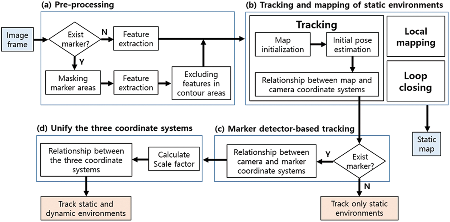
Figure 1: Configuration diagram of the proposed tracking system (a) Pre-processing (b) Tracking and mapping of static environments (c) Marker detector-based tracking (d) Unify the three coordinate systems
3.1 Preparation Steps for Tracking
For the proposed tracking system to work smoothly, we must divide the static and dynamic environments in real space. Here, the dynamic environment is defined as a potentially moveable environment for AR applications. The proposed system consists of a combination of feature-based SLAM and a marker detector, and each module tracks static and dynamic environments. AR application developers must attach markers to each dynamic element to track potentially moving objects. Tracking of a dynamic element (object) estimates a 3D pose based on the detection of a square marker. Additionally, because the marker has a unique pattern, it is possible to classify the dynamic elements.
In this study, an indoor space is targeted as an example of a real space for an AR application (see Fig. 2). In the static environment, a diorama and surrounding stationary objects are used, and in the dynamic environment, a moveable toy train is targeted. Because the toy train is a dynamic element, a marker is attached to it to track the pose.
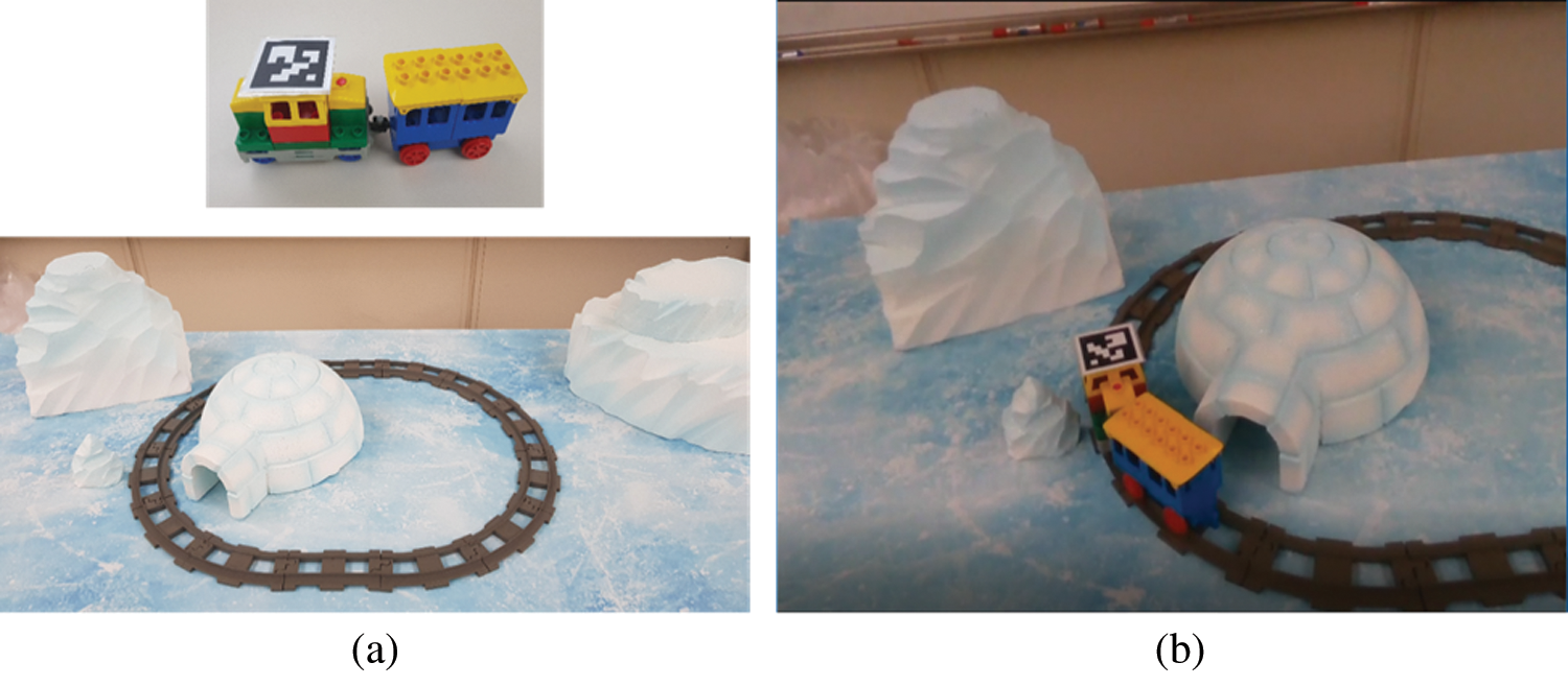
Figure 2: Example of real spaces for AR applications: (a) Example of a static environment (diorama) and a dynamic environment (toy train); (b) Concept for an AR application in this paper
3.2 Tracking and Mapping Only a Static Environment in Real Space
This section describes how to track and map only the static environment of the real space defined in Section 3.1.
3.2.1 Pre-Processing: Masking of Dynamic Elements
For each image sequence, we segment potential moving elements for the following reasons. First, calculating the relationship (pose) between the static scene and the camera is important, and estimating the 3D pose of the dynamic elements (objects) is required.
First, the marker is detected in each frame as an RGB image. We implemented our marker detection module using the ArUco marker detector [35]. Then, the pose of the marker attached to the dynamic element is obtained, and the value is transferred to the step of tracking the dynamic element (Section 3.3.1). However, because conventional visual SLAM assumes that the observed surrounding environment is stationary, the SLAM system may not work well in static and dynamic environments.
Therefore, from the image with the marker masked for each frame, we extract the features and pass them to the tracking and mapping step in the static environment (Section 3.2.2), which is used to calculate the relationship between the static scene and the camera. At this time, because the segment contours of the masked area tend to show prominent point features as high-gradient areas, the features of those areas are excluded from tracking. In this step, like the study in [36], we estimate the camera pose in a static environment by tracking a simplified version of ORB-SLAM2 [7].
To accurately obtain the relationship between the static scene and the camera in real space (Section 3.1), we extend the ORB-SLAM2 [7], a system that tracks features quickly and accurately by generating a sparse map. When using a monocular image as an input in ORB-SLAM2, an automatic map initialization method is performed, but the exact scale of the map coordinate system cannot be estimated. The proposed system needs to know the exact scale to transform the marker pose in the marker coordinate system into the SLAM coordinate system (Section 3.3). Therefore, in the case of the monocular image, scale estimation is performed during the map initialization step. During implementation, the scale of the SLAM map coordinate system is applied as a real scale using the depth image.
After map initialization, tracking, mapping, and loop-closing are performed via three threads. First, in the tracking thread, ORB features are extracted, excluding pixels corresponding to the dynamic environment (Section 3.2.1) to perform tracking and mapping on RGB (or RGB-D, stereo) image sequences. Fig. 3 shows the matched features in the static environment, excluding the area of the marker and the contour part. Finally, the camera pose is estimated using successive consecutive matching features. The mapping and loop closing threads operate in the same way as in [7].
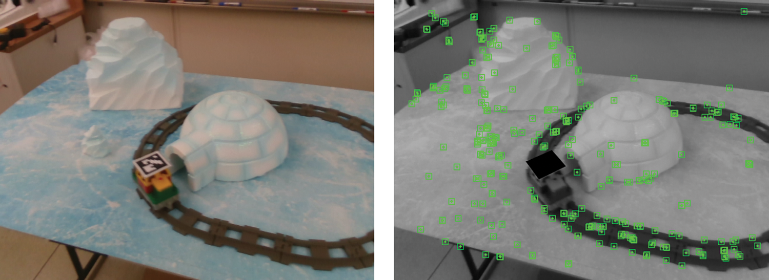
Figure 3: Matched features in the static environment: (left) input image, (right) example of feature (green rectangle) matching (except for markers and contour features)
We implemented the save and load functions of the static map, including elements such as points, keyframes, and co-visibility graphs, via boost serialization. This has the advantage of being able to perform SLAM-based localization by loading a static map without mapping from the beginning if the real space to which AR is applied is known in advance.
3.3 Simultaneous Tracking of Static and Dynamic Environments
In this section, we show how to track the dynamic environment in Section 3.3.1, and Section 3.3.2 describes the simultaneous tracking of static and dynamic environments in the same coordinate system. Finally, Section 3.3.3 describes the combination of static map-based camera localization and tracking of the dynamic environment.
3.3.1 Tracking Dynamic Elements
If the tracking of the static environment is successful (Fig. 1b), then tracking of the dynamic environment is activated. A marker detector is used to track the dynamic elements (Fig. 1c). Because we stored the actual size of the marker and the ID of the marker pattern in a dictionary, it is possible to determine the scale of the marker coordinate system and recognize the dynamic elements.
In this step, if one or more markers are detected in the current frame, the 3D pose of the marker is estimated. In this case, the pose between the camera and the marker understands the initial relationship using the perspective-n-point algorithm. It then performs subfix refinement to minimize the error. Through the refined pose estimation, we finally determine the relationship between the camera coordinate system and the marker coordinate system.
3.3.2 Joint of Static and Dynamic Environment Coordinate Systems
This section describes how to transform the pose of the dynamic elements in the marker coordinate system into the SLAM map (static environment) coordinate system. Fig. 4 shows the relationship between the SLAM map, camera, and marker coordinate systems. Let PSLAM be a point in the SLAM map coordinate system. The points in the camera and marker coordinate systems are
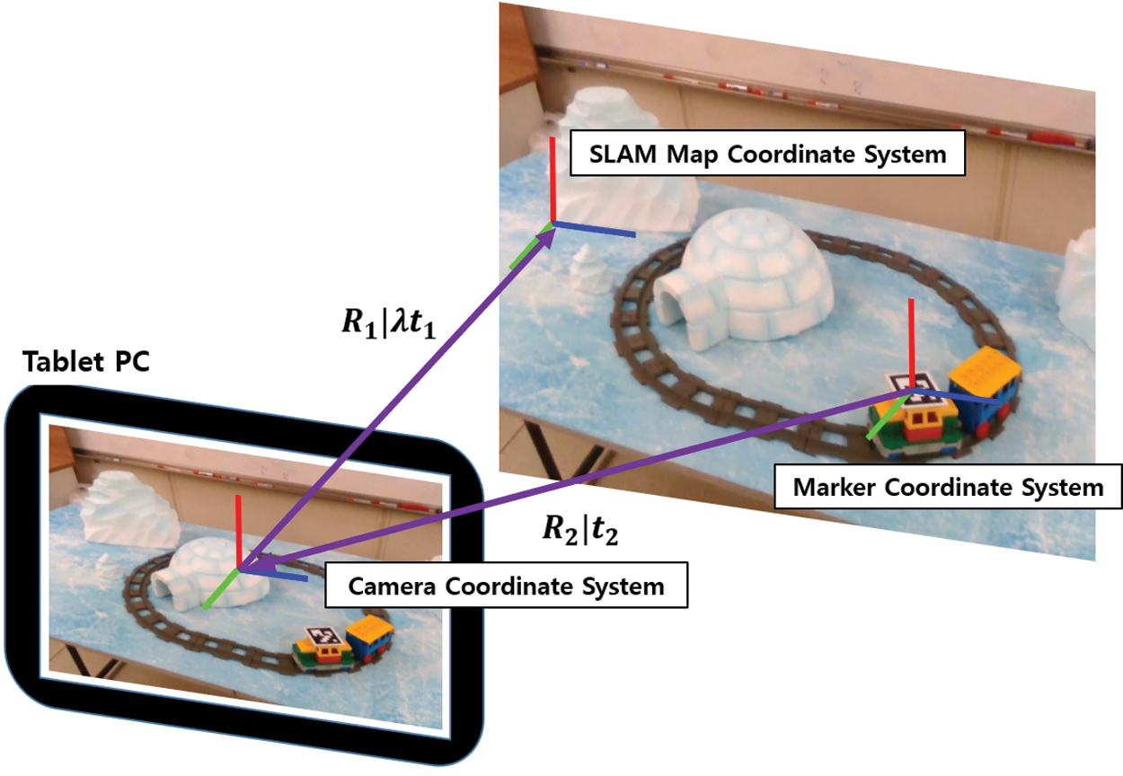
Figure 4: Relationship between the three different coordinate systems
First, the conversion relationship between the SLAM map coordinate system and the camera coordinate system is as follows, where R1 and t1 are the rotation and translation matrices, respectively, from the camera to the SLAM map coordinate system:
The conversion relationship between the camera and marker coordinate systems can be computed, where R2 and t2 are the rotation matrix and the translation matrices, respectively, from the marker to the camera coordinate system:
Finally, using Eqs. (1) and (2), the relationship between the SLAM map coordinate system and the marker coordinate system can be calculated as follows:
According to Eq. (3), the pose of the dynamic object (marker) in the SLAM map coordinate system is obtained as shown in Fig. 4.
In addition to determining
Fig. 5 shows an example of the visualization of the camera, the static map, and the marker in the same SLAM coordinate system through the proposed system. It can be seen that the marker image is normally visualized according to the movement of the dynamic object alongside the static map (i.e., 3D point cloud) and the camera.
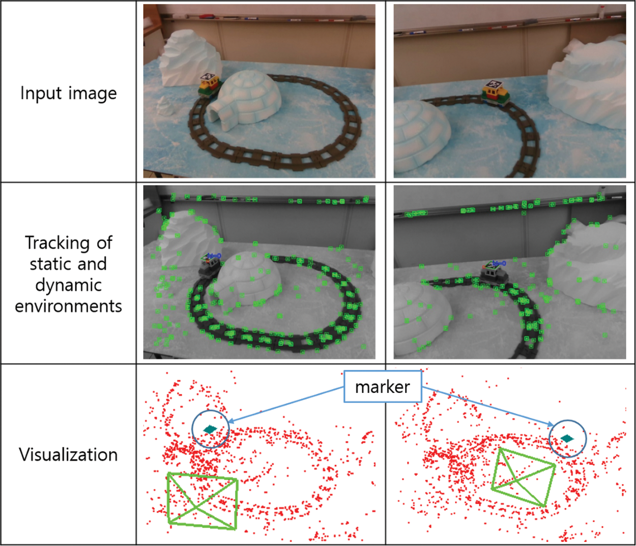
Figure 5: Visualization of a camera, a static map, and a marker in the SLAM map coordinate system
3.3.3 Tracking of Static and Dynamic Environments Based on a Static Map
If we have a static map, we can load it (Section 3.2.2) before the tracking stage. If the static map is well-made, the proposed system can track static and dynamic environments without additional mapping.
Specifically, the tracking mode in this section differs from the proposed system in Fig. 1b. First, local mapping and loop-closing threads are turned off, and only the tracking thread is performed. In the tracking thread, instead of map initialization, a static map is loaded, and global localization is performed. Global localization converts frames into bags of words and queries the recognition database for keyframe candidates in the loaded map. For each keyframe, the camera pose is estimated by calculating the corresponding relationship with the ORB associated with the map point. If the pose estimation is successful, the conversion relationship between the static map and the camera coordinate system is calculated, and finally, the camera pose in the SLAM map coordinate system is obtained. During implementation, we used the localization mode to turn off the mapping and loop closing of ORB-SLAM2 [7].
In Section 4.1, we investigate whether the SLAM module of the proposed system tracks and maps only the static environment. Section 4.2 analyzes the 3D trajectory of the markers in the SLAM map coordinate system when static and dynamic environments are tracked by the proposed system.
4.1 Experiment 1: Performance Evaluation of SLAM Module with Marker Masking
The SLAM module of the proposed system tracks and maps the surrounding environment, apart from the features of the marker area, including the edge part. In this experiment, we evaluated the tracking performance and static map quality of the proposed SLAM module.
We conducted Experiment 1 in a real space comprising a dataset (

Figure 6: Dataset with static and dynamic environments used for Experiment 1 (
4.1.1 Evaluation 1: Comparison of Matching Features in a Dynamic Element
First, we activated the SLAM module of the proposed system alongside ORB-SLAM2 [7] in
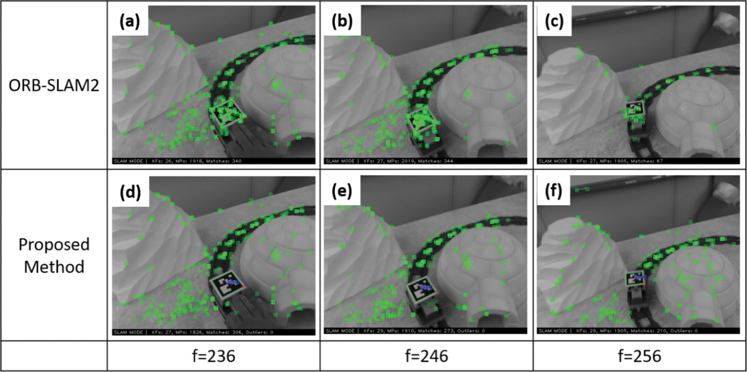
Figure 7: Example of features matched by two methods in
In ORB-SLAM2, when the toy train was not moving, as shown in Fig. 7a, the features were uniformly matched not only in the static environment but also at the toy train to which the marker was attached. As shown in Fig. 7c, when the stationary toy train started to move, the number of matching features in the static environment was significantly reduced, which is thought to affect the tracking and mapping performance. The number of features matching the static environment was significantly reduced, which is thought to affect tracking and mapping performance. On the other hand, in the proposed method, there was a small number of matching features on the toy train, as shown in Fig. 7d, and when the dynamic element moves as shown in Fig. 7f, only the static environment was considered as the matching feature for stable tracking.
The total number of matching features in
Fig. 9 shows the ratio (%) of the matches for the dynamic element in the total number of matching features. In ORB-SLAM2, it can be observed that when the toy train began to move, the ratio increased significantly from approximately 236 to 270 frames. However, the proposed method maintains a constant value, even when the toy train moves, which excludes the matching features near the toy train.
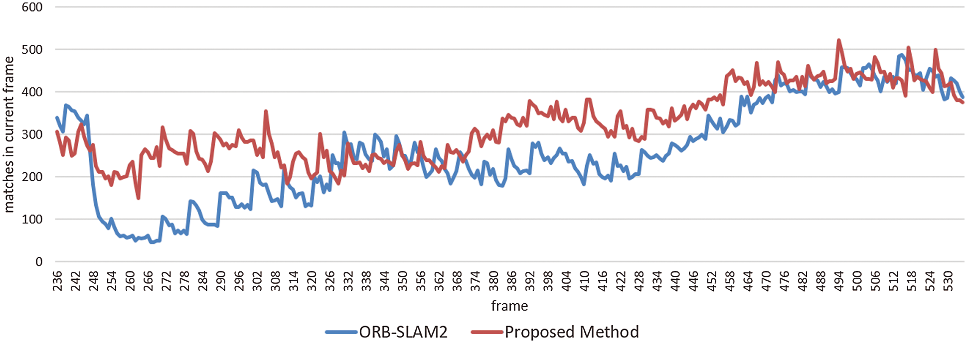
Figure 8: Comparison of the total number of matching features from the time the toy train moves

Figure 9: Ratio (%) of the matches on the dynamic element in the total number of the matching features in each frame from the time the toy train moves
4.1.2 Evaluation 2: Comparison of Quality of SLAM Maps
In this section, we evaluate the SLAM map generated by the proposed method using
-
-
-
The 3D point clouds of the three SLAM maps were observed from three viewpoints (➀ –➂ in Fig. 10). Compared to
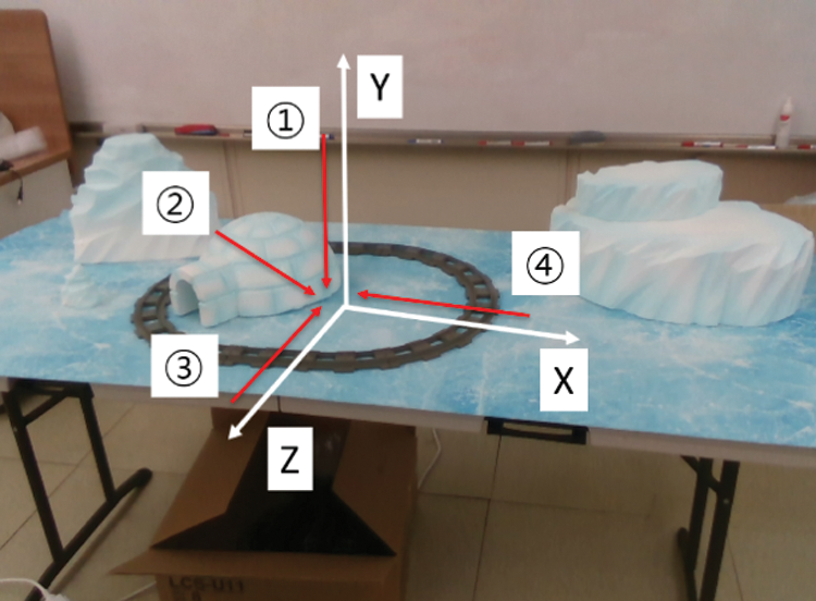
Figure 10: Examples of viewpoints from the Experiments 1 and 2
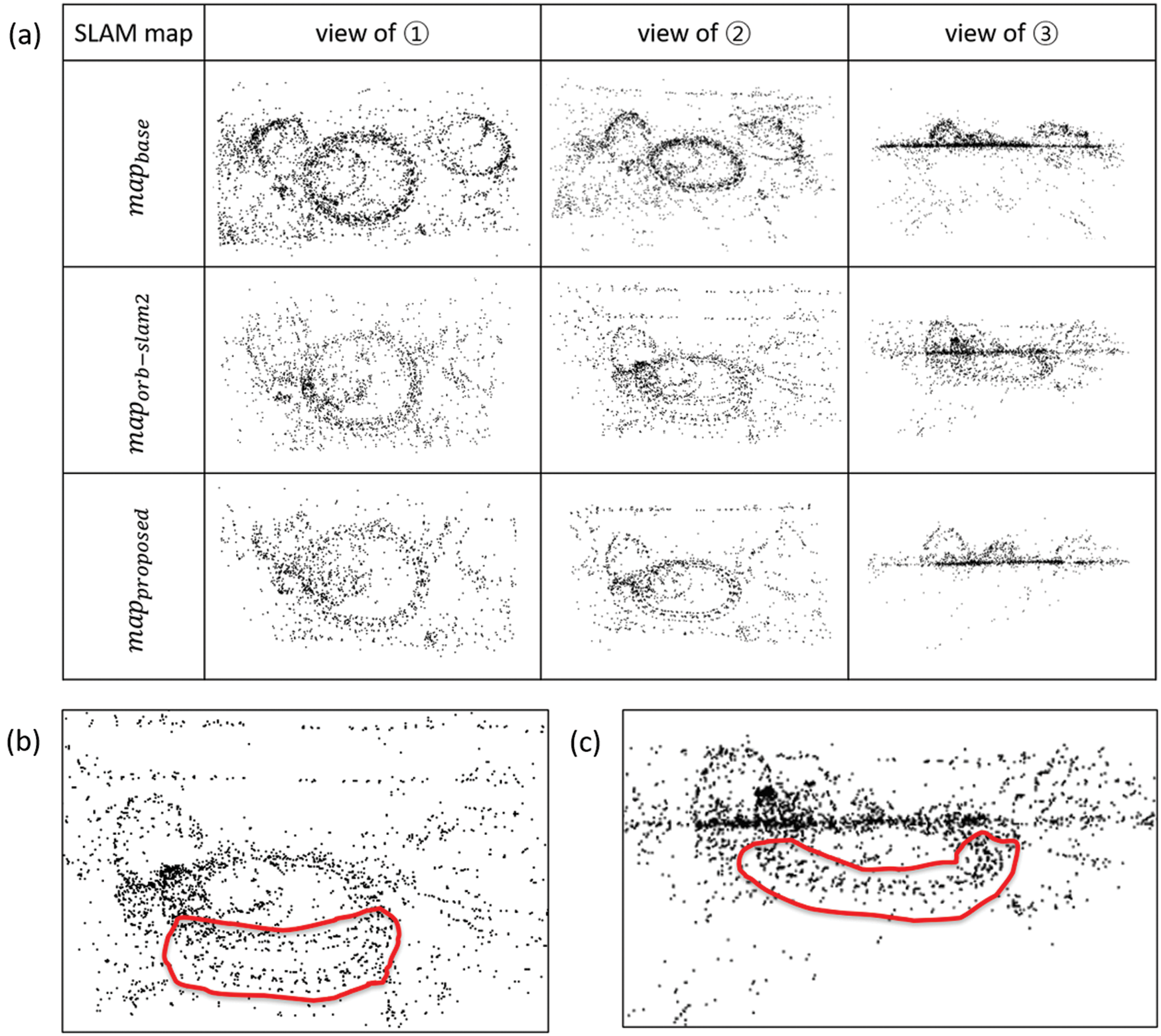
Figure 11: (a) Comparison of three generated maps based on SLAM (b)
4.2 Experiment 2: 3D Trajectory Analysis of a Dynamic Element in SLAM Map Coordinate System
In this section, we analyze the 3D trajectory of the marker pose in the SLAM map coordinate system when static and dynamic environments are tracked using the proposed system. The experiment was carried out as follows:
1. Because the purpose of the experiment was to analyze the marker pose in the SLAM map coordinate system, a static map of
2. Load the static map (created in (1)) and track the static scene and dynamic elements at the same time in
3. Obtain the 3D coordinates of the marker center point and the normal vector in the SLAM map coordinate system.
As shown in Fig. 12, the SLAM map of the 3D point cloud (red cube) and the trajectory of the marker (green sphere) observed in four views (➀ –➃ in Fig. 10) were rendered and visualized in Unity 3D.
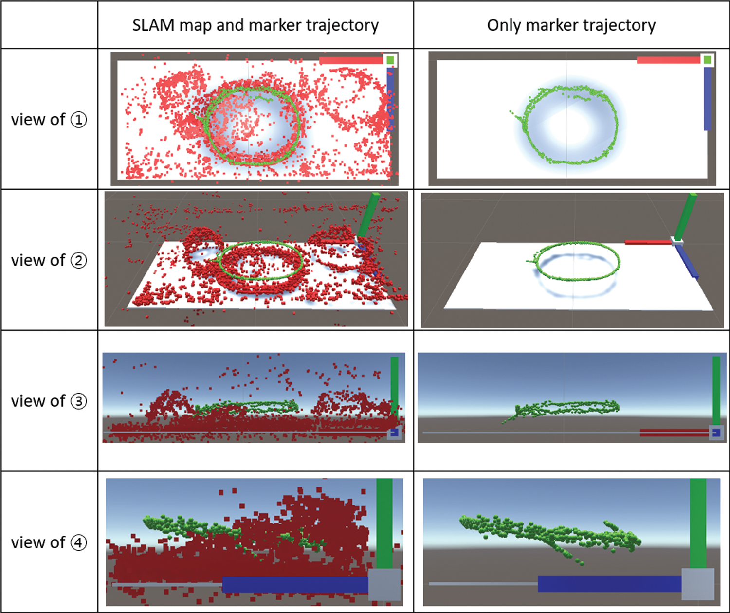
Figure 12: SLAM map of the 3D point cloud (red cube) and the trajectory of the marker (green sphere) observed in four views (➀
4.2.1 Evaluation 1: Trajectory Analysis of Marker Origin from Top-Down View (View of ➀ in Fig. 10)
It can be observed that the path of the dynamic element (toy train) tracked by the proposed system generally moves along the shape of the train rail, but some of the movements are deviated. As a result of analyzing the area beyond the train rails, it is presumed that the marker recognition failed because of image blur, or the marker pose was misestimated due to marker ambiguity. Additionally, in this evaluation, the proposed system tracked
Next, to calculate the angle between the normal vector of the diorama plane (

Figure 13: (a) Angle between
4.2.2 Evaluation 2: Distance from Bottom Plane of Diorama to Marker Origin
When viewed from the front and side views (views of ➂ and ➃ in Fig. 10), the height from the diorama plane to the marker origin in the SLAM map coordinate system can be determined, and the height in each frame is shown in Fig. 14a.
In Fig. 12 (view of ➃ ), the height from the plane to the origin of the marker tends to be higher on the side closer to the camera. The SLAM map prepared in the experiment was created based on the dataset (

Figure 14: (a) Height of the marker origin from the diorama plane, (b) The difference value from the reference height
5.1 An Example of an AR Application
We created an example of an AR application called ARTrain [39] (Fig. 15) based on the proposed tracking system and demonstrated it using Microsoft Surface Pro 4 (Intel Core i7 6600 CPU, Windows 10 OS) and Intel RealSense D435i camera. The proposed system has the advantage of registering virtual content by tracking both static and dynamic environments simultaneously. As shown in the example in Fig. 15, the virtual objects (trees and animals) and the effect of snow were expressed on the SLAM map (static environment), and train smoke was provided from the marker on the moving train so that users could experience more realistic AR content.
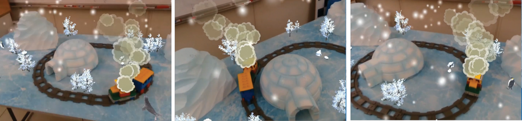
Figure 15: ARTrain [39]
5.2 Strategy for Creating AR Applications
We believe that our proposed system can be applied to a variety of scenarios beyond the example shown in Section 5.1 by attaching a marker to any dynamic object when the objects are known in advance along with their static environment. To create AR applications, including static and dynamic environments, the following two scenarios can be considered when using the proposed tracking system:
1. Augment each virtual object on the SLAM map and marker (ARTrain [39] in Section 5.1).
2. Interactions that understand the SLAM map, camera, and marker (dynamic element).
In the case of Scenario 2, because the SLAM map, camera, and marker are placed on the same SLAM map coordinate system, the proposed system understands each element to enable richer interaction. For example, if a virtual character in a diorama (the SLAM map side) jumps and climbs on a train (the marker side), the virtual character can move along with the train. Additionally, we can register a virtual character on the train (the marker side) to greet the user (the camera side) while looking at it.
Unlike previous studies that tracked both static and dynamic environments at the same time, our proposed system tracks using a marker detector. Thus, it can accurately estimate the reference pose of a dynamic element to be tracked, and it operates in real-time, even on a mobile device. Furthermore, it is possible to accurately identify an object through the ID of the marker so that various types of dynamic objects can be arranged to provide rich interaction.
Another advantage of the proposed system is that it can be extended in various directions using AR applications based on the conventional SLAM system (ORB-SLAM2 [7]). In the proposed system, the marker detector module is combined with the SLAM module, and depending on the purpose of the application, dynamic elements can be additionally placed in a real space, and virtual objects can be registered with the element. On the other hand, the proposed system can use the conventional SLAM-based AR application because the marker detector does not operate in a real space without dynamic elements. Accordingly, because there is no need to change the tracking algorithm according to the addition/removal of dynamic elements, we can utilize AR resources as they are and reduce the application production time.
First, it is necessary to improve the performance of SLAM and its associated marker detector modules. Specifically, in the case of the SLAM module, ORB-SLAM2 [7], which is a relatively light algorithm, was used to operate in a mobile device. If developers need to create an application that requires additional real-world information (i.e., mesh and object classification in static scene), the tracking system becomes computationally heavy; thus, tracking speed can be improved in real-time. In the case of the marker detector, as shown in the experimental results in Section 4, there was a misestimation caused marker ambiguity. This can be solved by estimating the marker pose in the same way as in [40]. Furthermore, marker detection often fails because of image blur, and this can be solved by acquiring an image at a high frequency or by using specific cameras (i.e., global shutter or event types).
Next, if the marker image on the moving object is occluded by another environment, tracking the object is impossible. This problem is fundamentally the same as that of any other object detection task. To solve this problem, an additional camera was installed in a pose that is not occluded by the environment, and the marker pose was estimated through the camera and finally transmitted to the user’s device. Additionally, we added a deep learning-based marker [41] that enables robust pose estimation, even when the marker is partially occluded.
Finally, this study presented an application in the environment, including one dynamic element. However, because the proposed tracking method was implemented to recognize multiple markers, it was also possible to track multiple dynamic elements simultaneously. In fact, it was necessary to investigate the tracking performance in an environment that includes multiple dynamic elements and whether it can be extended to AR applications.
In this study, we introduced a novel system for tracking static and dynamic environments simultaneously by combining the marker detector module with the SLAM module. By adding the marker outlier process to the conventional SLAM module [7], only the static environment was tracked and mapped, and the marker attached to the dynamic object was tracked with the marker detector module to obtain the marker pose in the SLAM map coordinate system. We implemented a novel AR application using the proposed system and demonstrated that mobile devices can provide AR applications to static and dynamic environments in real spaces.
Although our system combined a lightweight marker detector to create real-time AR applications in static and dynamic environments, it has some limitations. Dynamic elements lacking markers cannot be tracked, and they are difficult to consider in AR applications. Furthermore, the tracking performance when dynamic elements with multiple markers are included has not been investigated. Overcoming these limitations should provide opportunities for future work.
Funding Statement: This work was supported by Institute of Information & communications Technology Planning & Evaluation (IITP) grant funded by the Korea Government (MSIT) (No. 2021-0-00230, ‘Development of real virtual environmental analysis based adaptive interaction technology’).
Conflicts of Interest: The authors declare that they have no conflicts of interest to report regarding the present study.
1. Kato, H., Billinghurst, M. (1999). Marker tracking and HMD calibration for a video-based augmented reality conferencing system. Proceedings of the 2nd IEEE and ACM International Workshop on Augmented Reality, pp. 85–94. San Francisco, CA, USA. [Google Scholar]
2. Williams, B., Klein, G., Reid, I. (2007). Real-time SLAM relocalisation. Proceedings of the 2007 IEEE 11th International Conference on Computer Vision, pp. 1–8. Rio de Janeiro, Brazil. [Google Scholar]
3. Klein, G., Murray, D. (2007). Parallel tracking and mapping for small ar workspaces. Proceedings of the 2007 6th IEEE and ACM International Symposium on Mixed and Augmented Reality, pp. 225–234. Nara, Japan. [Google Scholar]
4. Castle, R., Klein, G., Murray, D. W. (2008). Video-rate localization in multiple maps for wearable augmented reality. Proceedings of the 2008 12th IEEE International Symposium on Wearable Computers, pp. 15–22. Pittsburgh, PA, USA. [Google Scholar]
5. Park, S., Cho, H., Park, C., Yoon, Y., Jung, S. (2020). AR room: Real-time framework of camera location and interaction for augmented reality services. Proceedings of the 2020 IEEE Conference on Virtual Reality and 3D User Interfaces Abstracts and Workshops, pp. 736–737. Atlanta, GA, USA. [Google Scholar]
6. Mur-Artal, R., Montiel, J. M. M., Tardós, J. D. (2015). ORB-SLAM: A versatile and accurate monocular SLAM system. IEEE Transactions on Robotics, 31(5), 1147–1163. DOI 10.1109/TRO.2015.2463671. [Google Scholar] [CrossRef]
7. Mur-Artal, R., Tardós, J. D. (2017). ORB-SLAM2: An open-source SLAM system for monocular, stereo, and RGB-D cameras. IEEE Transactions on Robotics, 33(5), 1255–1262. DOI 10.1109/TRO.2017.2705103. [Google Scholar] [CrossRef]
8. Qin, T., Li, P., Shen, S. (2018). VINS-mono: A robust and versatile monocular visual-inertial state estimator. IEEE Transactions on Robotics, 34(4), 1004–1020. DOI 10.1109/TRO.2018.2853729. [Google Scholar] [CrossRef]
9. Saputra, M. R. U., Markham, A., Trigoni, N. (2018). Visual SLAM and structure from motion in dynamic environments: A survey. ACM Computing Surveys, 51(2), 1–36. DOI 10.1145/3177853. [Google Scholar] [CrossRef]
10. Runz, M., Buffier, M., Agapito, L. (2018). MaskFusion: Real-time recognition, tracking and reconstruction of multiple moving objects. Proceedings of the 2018 IEEE International Symposium on Mixed and Augmented Reality, pp. 10–20. Munich, Germany. [Google Scholar]
11. Rünz, M., Agapito, L. (2017). Co-fusion: Real-time segmentation, tracking and fusion of multiple objects. Proceedings of the 2017 IEEE International Conference on Robotics and Automation, pp. 4471–4478. Singapore. [Google Scholar]
12. Marchand, E., Uchiyama, H., Spindler, F. (2016). Pose estimation for augmented reality: A hands-on survey. IEEE Transactions on Visualization and Computer Graphics, 22(12), 2633–2651. DOI 10.1109/TVCG.2015.2513408. [Google Scholar] [CrossRef]
13. Rekimoto, J. (1998). Matrix: A realtime object identification and registration method for augmented reality. Proceedings 3rd Asia Pacific Computer Human Interaction, pp. 63–68. Shonan Village Center, Japan. [Google Scholar]
14. Comport, A. I., Marchand, E., Pressigout, M., Chaumette, F. (2006). Real-time markerless tracking for augmented reality: The virtual visual servoing framework. IEEE Transactions on Visualization and Computer Graphics, 12(4), 615–628. DOI 10.1109/TVCG.2006.78. [Google Scholar] [CrossRef]
15. Drummond, T., Cipolla, R. (2002). Real-time visual tracking of complex structures. IEEE Transactions on Pattern Analysis and Machine Intelligence, 24(7), 932–946. DOI 10.1109/TPAMI.2002.1017620. [Google Scholar] [CrossRef]
16. Vacchetti, L., Lepetit, V., Fua, P. (2004). Combining edge and texture information for real-time accurate 3D camera tracking. Proceedings Third IEEE and ACM International Symposium on Mixed and Augmented Reality, pp. 48–56. Arlington, VA, USA. [Google Scholar]
17. Davison, A. J., Reid, I. D., Molton, N. D., Stasse, O. (2007). MonoSLAM: Real-time single camera SLAM. IEEE Transactions on Pattern Analysis and Machine Intelligence, 29(6), 1052–1067. DOI 10.1109/TPAMI.2007.1049. [Google Scholar] [CrossRef]
18. Simon, G., Fitzgibbon, A. W., Zisserman, A. (2000). Markerless tracking using planar structures in the scene. Proceedings IEEE and ACM International Symposium on Augmented Reality, pp. 120–128. Munich, Germany. [Google Scholar]
19. Pressigout, M., Marchand, E. (2004). Model-free augmented reality by virtual visual servoing. Proceedings of the 17th International Conference on Pattern Recognition, 2, 887–890. DOI 10.1109/ICPR.2004.1334401. [Google Scholar] [CrossRef]
20. Ito, E., Okatani, T., Deguchi, K. (2011). Accurate and robust planar tracking based on a model of image sampling and reconstruction process. Proceedings of the 2011 10th IEEE International Symposium on Mixed and Augmented Reality, pp. 1–8. Basel, Switzerland. [Google Scholar]
21. Park, Y., Lepetit, V., Woo, W. (2011). Handling motion-blur in 3D tracking and rendering for augmented reality. IEEE Transactions on Visualization and Computer Graphics, 18(9), 1449–1459. DOI 10.1109/TVCG.2011.158. [Google Scholar] [CrossRef]
22. Wang, C. C., Thorpe, C., Thrun, S., Hebert, M., Durrant-Whyte, H. (2007). Simultaneous localization, mapping and moving object tracking. The International Journal of Robotics Research, 26(9), 889–916. DOI 10.1177/0278364907081229. [Google Scholar] [CrossRef]
23. Zou, D., Tan, P. (2013). CoSLAM: Collaborative visual SLAM in dynamic environments. IEEE Transactions on Pattern Analysis and Machine Intelligence, 35(2), 354–366. DOI 10.1109/TPAMI.2012.104. [Google Scholar] [CrossRef]
24. Jaimez, M., Kerl, C., Gonzalez-Jimenez, J., Cremers, D. (2017). Fast odometry and scene flow from RGB-D cameras based on geometric clustering. Proceedings of the 2017 IEEE International Conference on Robotics and Automation, pp. 3992–3999. Singapore. [Google Scholar]
25. Scona, R., Jaimez, M., Petillot, Y. R., Fallon, M., Cremers, D. (2018). StaticFusion: Background reconstruction for dense RGB-D SLAM in dynamic environments. Proceedings of the 2018 IEEE International Conference on Robotics and Automation, pp. 3849–3856. Brisbane, QLD, Australia. [Google Scholar]
26. Tateno, K., Tombari, F., Navab, N. (2016). When 2.5D is not enough: Simultaneous reconstruction, segmentation and recognition on dense SLAM. Proceedings of the 2016 IEEE International Conference on Robotics and Automation, pp. 2295–2302. Stockholm, Sweden. [Google Scholar]
27. Salas-Moreno, R. F., Newcombe, R. A., Strasdat, H., Kelly, P. H. J., Davison, A. J. (2013). SLAM++: Simultaneous localisation and mapping at the level of objects. Proceedings of the 2013 IEEE Conference on Computer Vision and Pattern Recognition, pp. 1352–1359. Portland, OR, USA. [Google Scholar]
28. Caccamo, S., Ataer-Cansizoglu, E., Taguchi, Y. (2017). Joint 3D reconstruction of a static scene and moving objects. Proceedings of the 2017 International Conference on 3D Vision, pp. 677–685. Qingdao, China. [Google Scholar]
29. He, K., Gkioxari, G., Dollár, P., Girshick, R. (2017). Mask R-CNN. Proceedings of the 2017 IEEE International Conference on Computer Vision, pp. 2980–2988. Venice, Italy. [Google Scholar]
30. Yang, S., Scherer, S. (2019). CubeSLAM: Monocular 3-D object SLAM. IEEE Transactions on Robotics, 35(4), 925–938. DOI 10.1109/TRO.2019.2909168. [Google Scholar] [CrossRef]
31. Xiao, Z., Wang, X., Wang, J., Wu, Z. (2017). Monocular ORB SLAM based on initialization by marker pose estimation. Proceedings of the IEEE International Conference on Information and Automation, pp. 678–682. Macao, China. [Google Scholar]
32. Wu, Z., Wang, P., Che, W. (2018). A method of registering virtual objects in monocular augmented reality system. Chinese Conference on Image and Graphics Technologies, pp. 483–493, Singapore: Springer. [Google Scholar]
33. Muñoz-Salinas, R., Medina-Carnicer, R. (2019). UcoSLAM: Simultaneous localization and mapping by fusion of keypoints and squared planar markers. Pattern Recognition, 101(5), 107193. DOI 10.1016/j.patcog.2019.107193. [Google Scholar] [CrossRef]
34. Pfrommer, B., Daniilidis, K. (2019). TagSLAM: Robust SLAM with fiducial markers. arxiv: 1910.00679. [Google Scholar]
35. Garrido-Jurado, S., Muñoz-Salinas, R., Madrid-Cuevas, F. J., Medina-Carnicer, R. (2016). Generation of fiducial marker dictionaries using mixed integer linear programming. Pattern Recognition, 51(C), 481–491. DOI 10.1016/j.patcog.2015.09.023. [Google Scholar] [CrossRef]
36. Bescos, B., Fácil, J. M., Civera, J., Neira, J. (2018). DynaSLAM: Tracking, mapping, and inpainting in dynamic scenes. IEEE Robotics and Automation Letters, 3(4), 4076–4083. DOI 10.1109/LRA.2018.2860039. [Google Scholar] [CrossRef]
37. Fujimoto, S., Hu, Z., Chapuis, R., Aufrère, R. (2016). ORB-SLAM map initialization improvement using depth. Proceedings of the 2016 IEEE International Conference on Image Processing, pp. 261–265. Phoenix, AZ, USA. [Google Scholar]
38. Mur-Artal, R., Tardós, J. D. (2017). Visual-inertial monocular SLAM with map reuse. IEEE Robotics and Automation Letters, 2(2), 796–803. DOI 10.1109/LRA.2017.2653359. [Google Scholar] [CrossRef]
39. Park, C., Cho, H., Park, S., Yoon, Y., Jung, S. (2020). AR train: Combining SLAM with a marker detector for AR applications in static and dynamic environments. Proceedings of the 11th Augmented Human International Conference, 23, 1–2. DOI 10.1145/3396339.3396398. [Google Scholar] [CrossRef]
40. Muñoz-Salinas, R., Marín-Jimenez, M. J., Medina-Carnicer, R. (2019). SPM-SLAM: Simultaneous localization and mapping with squared planar markers. Pattern Recognition, 86(Supplement C), 156–171. DOI 10.1016/j.patcog.2018.09.003. [Google Scholar] [CrossRef]
41. Hu, D., DeTone, D., Malisiewicz, T. (2019). Deep ChArUco: Dark ChArUco marker pose estimation. Proceedings of the 2019 IEEE/CVF Conference on Computer Vision and Pattern Recognition, pp. 8428–8436. Long Beach, CA, USA. [Google Scholar]
 | This work is licensed under a Creative Commons Attribution 4.0 International License, which permits unrestricted use, distribution, and reproduction in any medium, provided the original work is properly cited. |