| Computer Modeling in Engineering & Sciences |
DOI: 10.32604/cmes.2022.018543
ARTICLE
Reinforcement Effect Evaluation on Dynamic Characteristics of an Arch Bridge Based on Vehicle-Bridge Coupled Vibration Analysis
1National & Local Joint Engineering Laboratory of Bridge and Tunnel Technology, Dalian University of Technology, Dalian, 116023, China
2Design Institute of Civil Engineering & Architecture of Dalian University of Technology Co., Ltd., Dalian, 116023, China
3Faculty of Infrastructure Engineering, Dalian University of Technology, Dalian, 116023, China
*Corresponding Author: Xingwen He. Email: xingwen_he@dlut.edu.cn
Received: 01 August 2021; Accepted: 08 November 2021
Abstract: To numerically evaluate the reinforcement effect on dynamic characteristics of a concrete-filled steel tube arch bridge with vibration problems, a 12-degree-of-freedom sprung-mass dynamic vehicle model and a 3D finite element bridge model were established. Then, the coupled equations of vehicle-bridge interaction were derived and a computer program was developed using the FORTRAN language. This program can accurately simulate vehicle-bridge coupled vibration considering the bumping effect and road surface irregularity during motion of the vehicle. The simulated results were compared with those of relevant literatures to verify the correctness of the self-developed program. Then, three reinforcement schemes for the bridge (Addition of longitudinal beams, Reinforcement of bridge decks, and Replacement of suspenders) were proposed and numerically simulated, and the vibration reduction effects of the three schemes were evaluated based on the numerical results to find effective ones. It is confirmed that the reinforcement scheme of Addition of longitudinal beams shows the most significant vibration reduction effect. It is recommended in the engineering practice that the combination of the reinforcement schemes of Addition of longitudinal beams and Replacement of bridge deck can be used to solve the excessive vibration problem.
Keywords: Arch bridge; vehicle-bridge coupled vibration; reinforcement; numerical evaluation
The girder system of many half-through concrete-filled steel tube arch bridges constructed in the past is a type of suspended-deck structure, characterized by simple structure, clear force conditions, and convenient construction. However, since the suspended-deck system is not equipped with longitudinal beams, the deck is directly laid on cross beams. Because there is only concrete poured at the joints of the bridge decks, the overall rigidity of the bridge tends to be insufficient. When a vehicle is passing through the bridge, the vertical vibration of the bridge deck may become excessive, rendering pedestrians and drivers on the bridge uncomfortable, even panicky [1,2]. This type of bridge usually shows some common structural deteriorations, including (1) cracks, damaged railings, blocked expansion joints in the pavement structure, (2) disengaged steel-concrete structure of arch ribs, (3) damaged suspenders, (4) leakage, erosion and exposed rebars in bridge deck, (5) cracks and exposed rebars on cross-beams bottoms, etc. According to the force analysis on the concrete-filled steel tube arch bridges, it can be seen that the structure features a low structural damping ratio, a low natural frequency of vibration, and a low ability to dissipate external energy input. The main reasons for those bridge deteriorations are the insufficient rigidity of the suspended-deck system and the subsequent poor continuity of the overall structure of the bridge.
The bridge vibration problems became the key factor in the reinforcement and maintenance schemes to deal with the above bridge deteriorations. According to the recent Technical Code for Concrete-Filled Steel Tube Arch Bridges (GB 50923-2013, in Chinese) [3], for suspension arch bridges with horizontal beams as the main force bearer constructed in the past, the longitudinal rigidity of bridges must be increased by adding longitudinal beams to reduce the vibration. So, longitudinal beams are an important part of the reinforcement scheme. In addition, the reformation and replacement of bridge structures such as suspenders and bridge decks are also important for the bridge maintenance.
On the other hand, with the increase of traffic volume, traffic density, vehicle load and driving speed, the impact effect of running vehicles on bridges is becoming more and more intense. The coupling effect between vehicles and bridges is also a key concern of bridge designers. Accurate considerations of the vehicle-bridge coupling effect can also provide an excellent theoretical basis for the reformation and reinforcement of bridges after deteriorations occur [4].
Theories for vehicle-bridge coupled vibration can date back to the studies on such problems of railway bridges. In 1849, British scholar Willis R. proposed that the collapse of the Chester railway bridge was caused by bridge vibration due to uneven bridge decks when a train was passing through the bridge. Since then, scholars have studied and analyzed the problem of train-bridge interaction prosperously [5]. On the other hand, since the collapse of the Tacoma suspension bridge in the 1940s in the United States due to excessive vibration, vibration problems of highway bridges caused by wind loads and vehicle loads also gradually attracted the attention of scholars [6]. To this day, the vehicle model has gradually been developed from the original single-degree-of-freedom (DOF) plane model to the current multi-DOF 3D vibration system.
Tan et al. [7] established a 7-DOF vehicle model for vehicle-bridge coupled vibration analysis, and analyzed the effects of vehicle characteristics and road conditions on vehicle-bridge coupled vibration response. Mao et al. [8] established a three-axis six-DOF vehicle model, and analyzed the effects of three bridge modeling methods, i.e., beam grillage model, shell model, and entity model, on the vehicle-induced vibration response of a simply-supported beam as an example. Xie et al. [9] established a three-axis nine-DOF vehicle model, and introduced an incompatible entity finite element to build the bridge model to simulate the dynamic response of the bridge under a running vehicle. Korti et al. [10] used a simple bridge model to analyze the effect of the spatial vehicle model on the bridge vibration response in comparison with that of the plane vehicle model. He et al. [11–13] developed a 3D numerical procedure on vehicle or train-bridge coupled vibration system, which is applied to solve various problems such as traffic-induced environmental vibration, seismic response of train-bridge interaction system, and curved girder bridge vibration response under vehicle loads, etc.
However, there were few researches focusing on the running vehicle-induced vibration problem of concrete-filled steel tube arch bridges constructed in the past, especially considering accurate vehicle-bridge coupled vibration with sophisticated vehicle and bridge dynamic models and complicated real conditions. Therefore, the exploration and research on maintenance measures for old half-through concrete-filled steel tube arch bridges based on the vehicle-bridge coupled vibration analysis are very important for evaluations of bridge reinforcements and reformations, and will promote the development of future bridge constructions.
2 Numerical Procedures for Vehicle-Bridge Coupled Analysis [11–13]
2.1 Vehicle Vibration Formulae
According to the theory of vehicle dynamics based on d'Alembert's principle, a vehicle is assumed as a multi-rigid-body sprung-mass system, which is composed of the vehicle body, suspension devices and wheels connected by the primary and secondary suspension spring and damping systems. When different DOFs for each rigid body are considered due to actual needs, vehicle models with different DOFs can be established. In order to simplify calculation and analysis, the following assumptions were made for the vehicle model.
(1) The mass of each vehicle part such as the vehicle body, the suspension device and the wheel is concentrated at the center of mass;
(2) The vehicle body, suspension devices and other parts are regarded as rigid bodies, and are symmetrical structures transversely regarding to the center of mass;
(3) The vehicle body and suspension devices vibrate slightly from their equilibrium positions when the vehicle is in motion;
(4) The spring is linearly deformed, the damping is viscous damping, and the mass of the spring and damping system is ignored;
(5) The vibration of the vehicle model along the direction of vehicle movement is ignored;
(6) When the vehicle is running, it always maintains a uniform linear motion.
The vehicle model established in this study consists of 12-DOFs, including the motions of the vehicle body and the front and rear suspension systems, considering their nodding, rolling, vertical and lateral vibrations. For the vehicle suspension devices, the numerical model considers both the vertical and lateral spring and damping coefficients not only between the vehicle body and the suspension devices but also those between the suspension devices and the wheels. Therefore, the numerical model can fully consider the dynamic characteristics of the actual vehicle, and the simulation results can be more accurate.
The numerical vehicle model is shown in Fig. 1, and the variables defined in the model are shown in Table 1, respectively.
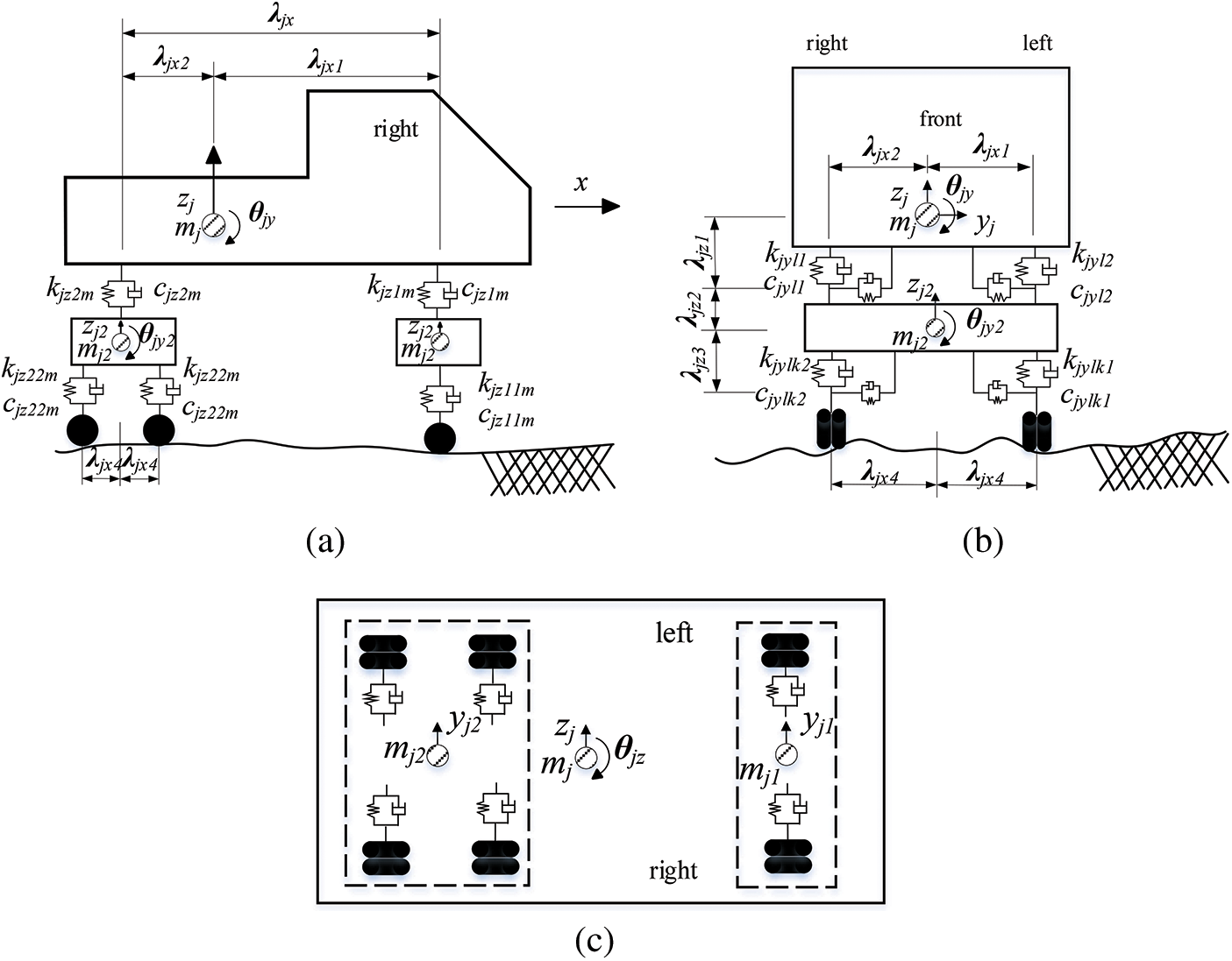
Figure 1: Vehicle sprung-mass model (a) Side view (b) Front viewl (c) Top view
Based on d'Alembert's principle, the vehicle vibration formulae for force balance in each DOF of the vehicle model are as follows [11–13]:
(1) Vibration formulae for the vehicle body
Yawing vibration:
Bouncing vibration:
Rolling vibration:
Nodding vibration:
Shaking vibration:
where,
In the above formulae, j represents the vehicle number. Letters l and m represent variables related to the vehicle body, i.e., l = 1 and 2 respectively represent the front and rear suspension devices of the vehicle body, and m = 1 and 2 respectively represent the left and right sides of the vehicle. lx(j) is a function of the vehicle number, and represents the number of vehicle suspensions. Letters x, y and z represent the three directions of the right-handed Cartesian coordinate system used in the vehicle model diagram.
vjlm(t) represents the force generated by the spring's extension (designated as a positive quantity) between the vehicle body and suspensions. Similarly, if the suspension is in front of the center of gravity, λjxl is a positive value, while if the axle is behind the center of gravity, λjxl is a negative value. Therefore, this formulae can be applied to vehicle models with any number of suspensions.
(2) Vibration formulae for the suspension devices
Yawing vibration:
Bouncing vibration:
Rolling vibration:
Nodding vibration:
where,
In the above formulae, the meaning of each subscript is as follows: Letter k = 1 and 2 represent the front and rear wheel axles of each suspension on the x coordinate axis, respectively. kx(l) is a function of the suspension and represents the number of wheel axles. vjlkm(t) represents the force generated by the spring's extension (designated as a positive quantity) between the suspension and wheel axles. Here, λjx(lx(j)+l) = λjx(3) = 0, because there is only one front wheel axle. The upper limit of the number of wheel axles is k = kx(l) = 2.
wjylkm or wjzlkm represents the sum of the displacement of the bridge deck at the wheel and road surface contact point and the displacement of the wheel caused by road irregularity in its direction, as shown below:
where, wy(t, xjlkm) or wz(t, xjlkm) is the displacement of the bridge deck in each direction, and z0(t, xjlkm) is the road surface irregularity value at the wheel and road surface contact point.
where, ΨTjylkm(t) or ΨTjzlkm(t) is the distribution vector to distribute the wheel load at the wheel and road surface contact point to the nodes of the finite element.
The horizontal and vertical vehicle wheel loads are calculated with the following equations:
In the above equation, g is the acceleration of gravity. Based on the above equations, the matrix form of the vehicle vibration formulae can be obtained as follows:
where,
2.2 Vibration Formula for Bridges
Based on the finite element method and d'Alembert's principle, the vibration formula for the bridge can be expressed as follows:
where, Mb, Cb, Kb and Fb are the mass matrix, damping matrix, rigidity matrix and external force vector matrix, respectively.
2.3 Mechanism of Vehicle-Bridge Coupling
2.3.1 Mechanism of Displacement Coupling
If the wheels and the bridge are always in contact during the vehicle motion, the vertical displacement of a wheel is equal to the sum of the displacement of the bridge and the road surface irregularity at the wheel and road surface contact point, as the following equation:
where, w(t, xjlk) = ΨTjlk(t)wb represents the displacement caused by the deformation of the bridge, and z0 represents the irregularity value of the road surface, respectively.
When the wheel is between the beam element nodes i and i+ 1, its distances from the two nodes are a1 and a2, respectively. Assuming that the displacements of the two nodes i and i+ 1 are respectively ωi and ωi + 1, the bridge displacement ωb at the wheel and road surface contact point can be expressed as follows:
2.3.2 Mechanism of Contact Force Coupling
The external excitation force received by the bridge at the wheel and road surface contact point is composed of the weights of the vehicle body, suspension devices, wheels, and the forces resulted from the spring-damping systems, and the equations are shown as below:
where Fb is the wheel load vector received by the bridge nodes. Here, Pjylkm(t) and Pjzlkm(t) respectively represent the wheel loads on each direction.
2.4 Formulae for Vehicle-Bridge Coupling System
Based on the equations above, the coupling formulae for the vehicle-bridge interaction system can be obtained and expressed as the following matrix form. Herein, Mb*, Cb* and Kb* respectively represent the bridge mass, damping, and rigidity matrices, considering the influence of the vehicle loads. Cbv and Kbv respectively represent the coupling components of the vehicle-bridge system, and Fb and Fv respectively express the external force vectors.
3 Program Development and Verification for Vehicle-Bridge Coupled Vibration
3.1 Numerical Integration Method for Solving the Vehicle-Bridge Coupled Equation
Generally, the exact solution to the formulae for vehicle-bridge coupled vibration cannot be obtained, and the numerical solution is usually obtained through numerical integration [14].
This program adopts the Newmark-β method to calculate the equations for vehicle-bridge coupled vibration. Two parameters α and β are introduced, and different methods for solving differential equations can be realized by adjusting these parameters.
The basic assumptions of the Newmark-β method are as follows:
where the two parameters α and β can be adjusted by selecting different values according to specific requirements, such as to meet accuracy and stability requirements. For example, when β = 1/6, α = 1/2, the linear acceleration method shall be applied, while when β = 1/4, α = 1/2, the average acceleration method shall be applied.
In order to ensure the unconditional stability requirement of the integral calculation, it usually requires:
From the joint calculation of the above Eqs. (30) and (31), the velocity and acceleration at the time can be derived, which are expressed as follows:
The equilibrium coupling vibration formula at time t + Δt can be expressed as follows:
Substituting Eqs. (33) and (34) into Eq. (35),
where
Then,
3.2 Numerical Simulation of Road Surface Irregularity
Road surface irregularity is an important factor in the vehicle-induced bridge vibration problem, which is the main external excitation of the vibration response of the vehicle-bridge coupled system. Previous studies usually did not consider the road surface irregularity or considered it as a sine function. Since the residual deformation of the bridge deck during the process of construction or use and road surface condition is random, the bridge surface irregularity is also a set of random numbers. At the present time, most studies assume that the road surface irregularity of the bridge is a Gaussian process. The Gaussian process is a steady and ergodic random process with the average value equal to zero, and the power spectral density of the Gaussian process is used to simulate the road surface irregularity of the bridge.
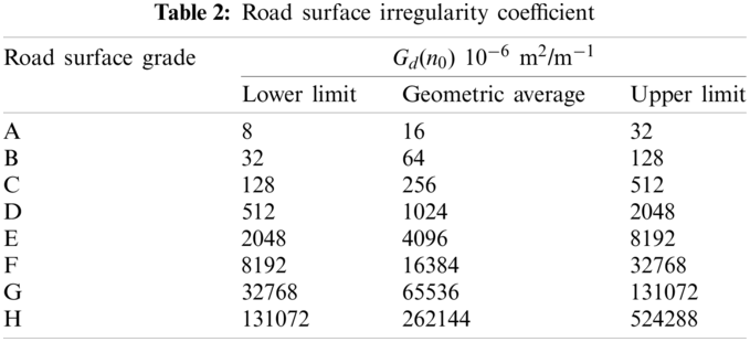
According to the Vehicle Vibration-Describing Method for Road Surface Irregularity (GB 7031-865), there is
where n represents the spatial frequency, and the unit is m−1. n0 represents the spatial reference frequency, and n0 = 0.1 m−1. w represents the frequency index, and the value for the road surface grade is 2. Gd(n0) represents the coefficient for road surface irregularity, and Gd(n) represents the displacement power spectral density, respectively.
Table 2 shows the lower limit, geometric average, and upper limit of the road surface irregularity coefficient corresponding to road surfaces of different grades.
The irregularity of the bridge surface is simulated in the frequency domain. In the vehicle-bridge coupled vibration analysis, the irregularity in the frequency domain needs to be converted into in the time domain for input. In this study, the triangle series method is selected to simulate the irregularity of the road surface. The equations are as follows:
Based on the year when the bridge was built and the traffic conditions, road surface irregularity of grade B is selected for the calculation in this study. According to the above equations, FORTRAN is used to develop the program, and the road surface irregularity of Grade B is calculated as shown in Fig. 2.
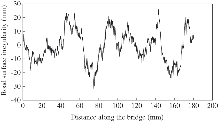
Figure 2: Road surface irregularity of Grade B
3.3 Development of the Program
3.3.1 Flow Chart of the Program
According to the formulae for vehicle-bridge coupled vibration established above, a computer program for solving the problem is developed using FORTRAN language, in which the Newmark-β method is adopted for the numerical integration to obtain the approximate solution of the differential equations. The program flowchart is shown in the Fig. 3.
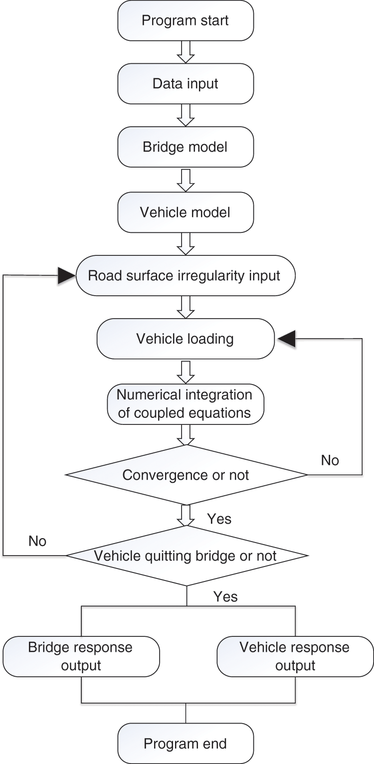
Figure 3: Solution flowchart of program
The vehicle-bridge coupled vibration analysis is a very complicated problem, and usage of sophisticated and reasonable numerical models considering real interaction mechanism is very important to ensure the accuracy of numerical results. In this study, a computer program is developed and coded with FORTRAN language, based on the d'Alembert's principle and the finite element method. A three-dimensional (3D) dynamic vehicle model and a 3D FE bridge model are established, taking into account the bumping effect and road surface irregularity influence during motion of the vehicle.
(1) This program can simulate a 12-DOF spatial running vehicle model. Thus, in the vehicle-bridge coupled vibration analysis, the actual vehicle vibration can be simulated more precisely, and more reliable numerical results can be obtained.
(2) This program can consider the bumping effect when the vehicle is running on the bridge. Therefore, the extreme situation in which a wheel leaves the road surface due to the bridge expansion joints or road surface irregularity can be simulated.
(3) This program can carry out the bridge vibration analysis, the vehicle vibration analysis, and the vehicle-bridge coupled vibration analysis separately without the assistance of any commercial software, which improves the efficiency of the numerical evaluation work.
3.4 Verification of the Self-Developed Program
The program was originally developed by the authors and its validity and reliability had been confirmed in the past researches [11–13]. In order to further verify whether the calculation results by this program of the vehicle-bridge coupled vibration analysis are correct, it is used to calculate the coupled vibration response of a double-DOFs vehicle model and a simply supported beam bridge model shown in Fig. 4, which is also calculated in the relevant literature [15], and the results obtained by both programs are compared for verification.
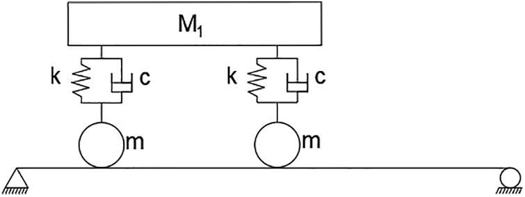
Figure 4: Double-DOF vehicle and beam bridge model
The bridge parameters is adopted as span length L = 30 m, bending rigidity E = 2.94 × e10 N/m2, bending moment of inertia of section I = 8.65 m4, mass per unit length m = 3.6 × e4 kg/m, and Poisson's ratio μ = 0.2.
The vehicle parameters is adopted as body mass M1 = 540 × 103 kg, body moment of inertia I = 1.38 × 10⁷ kg⋅ m2, wheel mass m = 0 kg, spring constant k = 4.135 × 10⁴ KN/m, damping coefficient c = 0 kN⋅s/m, axle distance d = 17.5 m, and running speed v = 27.78 m/s.
The comparison results are shown in Fig. 5. The vertical displacement at the span center of the simply supported beam and the acceleration of the vehicle body, obtained by both the program developed in this study and that from the literature [15], are used for the comparison. From the calculation results in Fig. 5, it can be seen that the results calculated by this program are basically consistent with those obtained by the relevant literature. Therefore, the validation of the program developed in this study can be demonstrated.
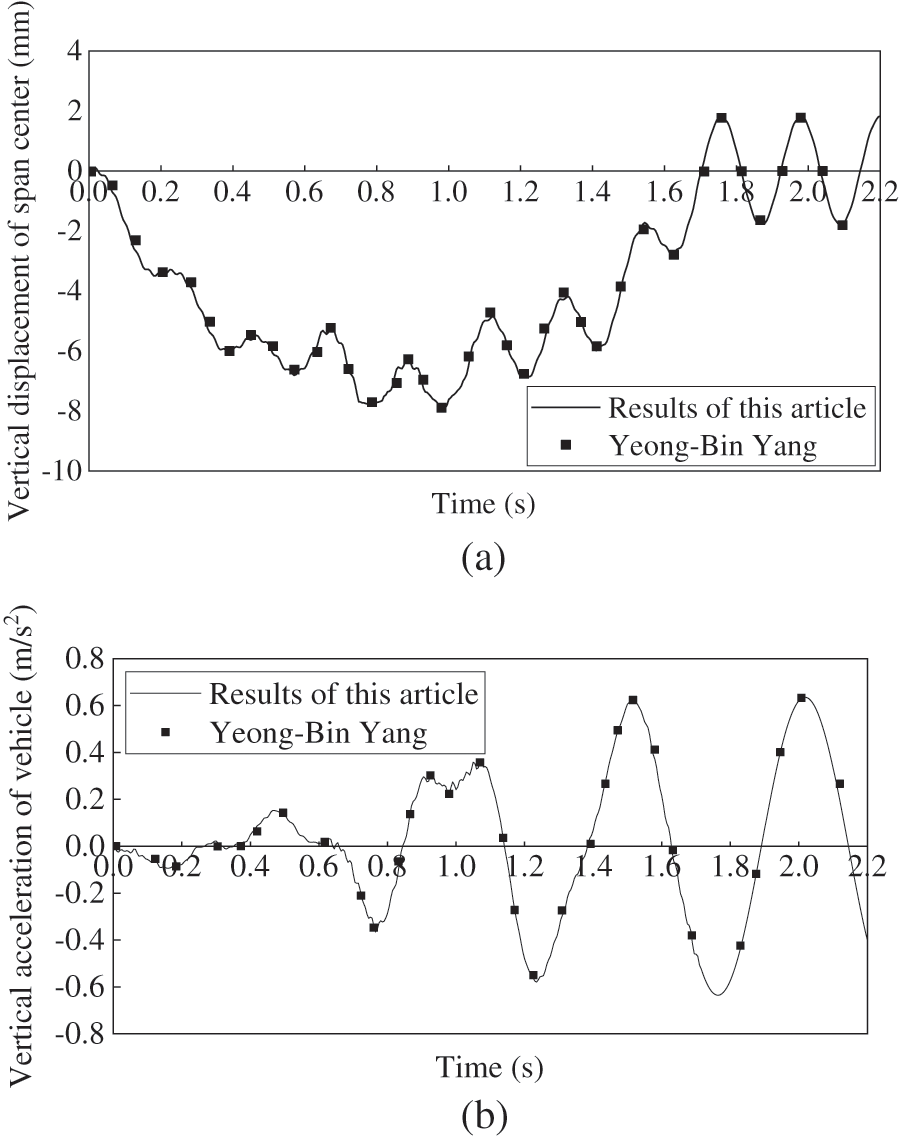
Figure 5: Results comparison for program verification (a) Vertical displacement of bridge span center (m) (b) Vertical acceleration of the vehicle (m/s2)
4 Reinforcement Schemes of the Bridge and Their Effects Evaluation
The bridge targeted in this study is a continuous half-through concrete-filled steel tube arch bridge with three spans (127 m + 148 m + 127 m), which was completed in Shenyang City, China in July 1997. The elevation and section views and the FE model of the bridge are respectively shown in Fig. 6.
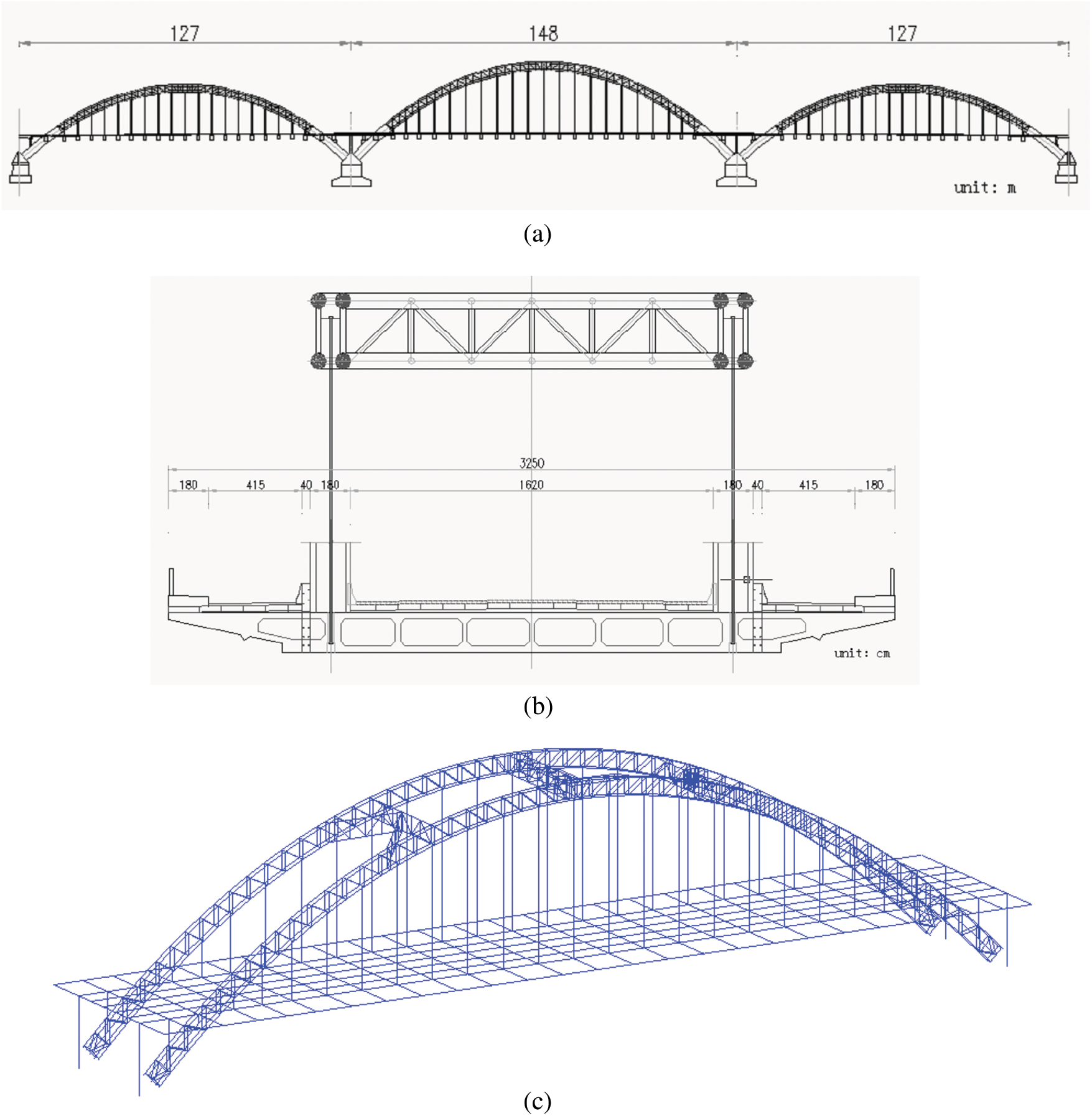
Figure 6: Targeted bridge structure and its FE model (a) Bridge elevation view (b) Bridge section view (c) Finite element model of the concrete-filled steel tube arch bridge
With the rapid development of the city and the increase in traffic volume, the bridge structure based on its original design is approaching its carrying capacity limit. Simultaneously, the vibration problem of the bridge deck structure is gradually becoming more and more significant in its actual use due to the design problem and structural deterioration. To deal with such problems, the bridge was reinforced later on, hoping to improve the dynamic characteristics of the structure and reduce the structural vibration response. However, the reinforcement effect was not sufficient and further countermeasures are needed to be discussed. Therefore, in this study, three reinforcement schemes are proposed due to the mechanism of actual deterioration problems, which respectively are Addition of longitudinal beams, Replacement of bridge deck, Replacement of suspenders. The details of the three schemes are shown in Table 3. The original bridge deck thickness is 0.25 m, and the original suspender diameter is 0.1 m.
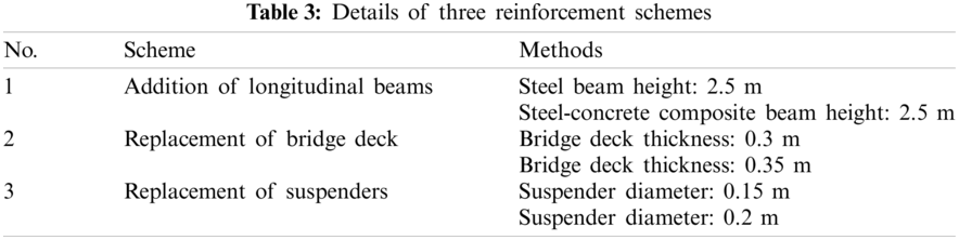
4.2 Effect Evaluation of Each Reinforcement Scheme
For calculation of vehicle-bridge coupled vibration, the following assumptions are made. The vehicle velocity is 60 km/h, and the road surface irregularity grade is grade B. The dynamic deflection, acceleration, and velocity of the bridge span center were calculated respectively, and the reinforcement effect of each reinforcement scheme on reduction of bridge vibration was compared.
4.2.1 Scheme 1--Addition of Longitudinal Beams
According to the two reinforcement plans of Addition of longitudinal beams proposed in Table 3, the dynamic deflection, acceleration, and velocity of the span center of the arch bridge calculated by the developed program are shown in Figs. 7–9, compared with those of the original bridge. The maximum values of the dynamic deflection, acceleration, and velocity of the span center for the two reinforcement plans, compared with those of the original bridge, and their reduction effects, are indicated in Table 4.
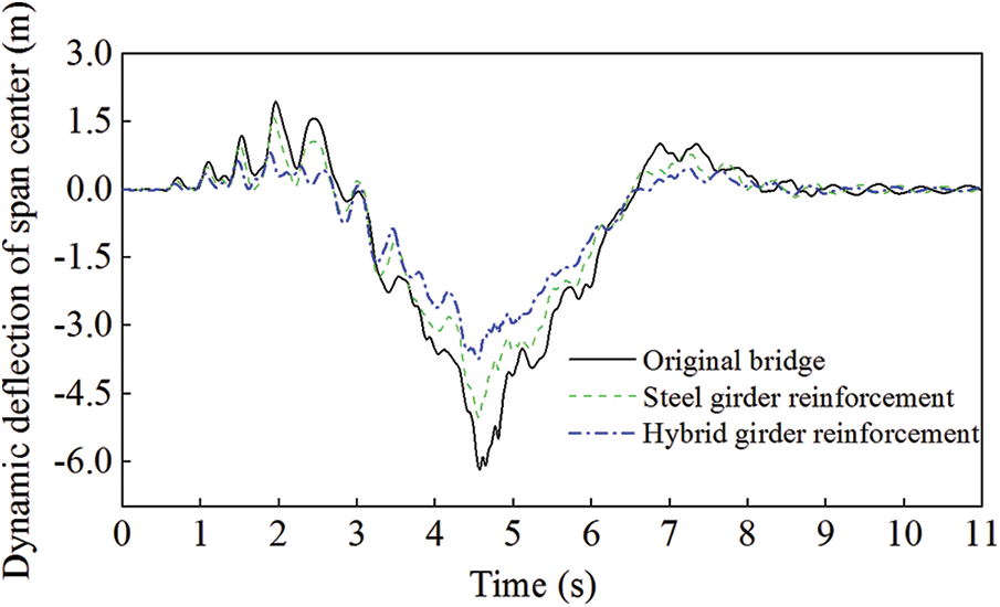
Figure 7: Comparison of the dynamic deflection for Scheme 1
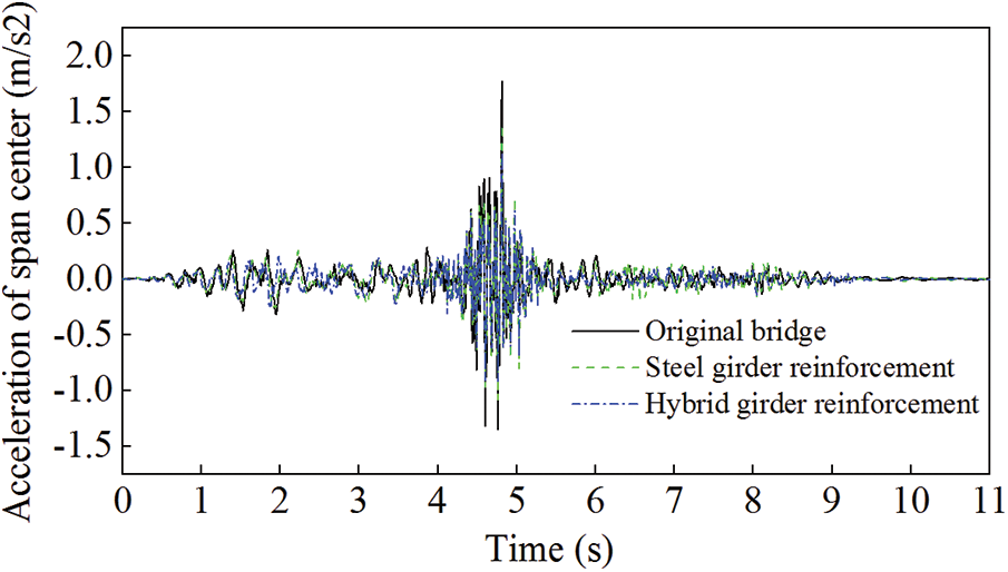
Figure 8: Comparison of the acceleration for Scheme 1
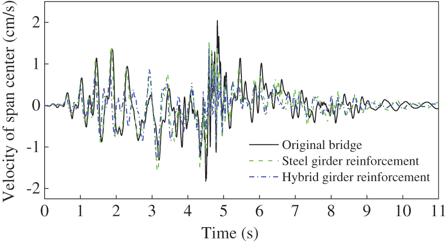
Figure 9: Comparison of the velocity for Scheme 1
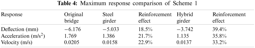
Comparison result shows that both the two reinforcement plans can significantly reduce the bridge vibration response. The effect of the reinforcement is more significant when the steel-concrete composite longitudinal beams were added than that of the longitudinal steel beams. In particular, the dynamic deflection of the span center in the composite longitudinal beam case decreases significantly than that of the steel beam case, while the difference in the decrease of velocity and acceleration is not so significant. Therefore, adding steel-concrete composite longitudinal beams is more effective on improving the bridge's longitudinal rigidity and is, therefore, a more reasonable reinforcement scheme.
4.2.2 Scheme 2--Replacement of Bridge Deck
According to the two reformation plans of different deck thicknesses proposed in Table 3, the thicknesses of the deck were respectively increased to 0.3 and 0.35 m form 0.25 m. The dynamic deflection, acceleration, and velocity of the span center of the arch bridge calculated by the developed program are shown in Figs. 10--12, compared with those of the original bridge. The maximum values of the dynamic deflection, acceleration, and velocity of the span center for the two reformation plans, compared with those of the original bridge, and their reduction effects, are shown in Table 5.
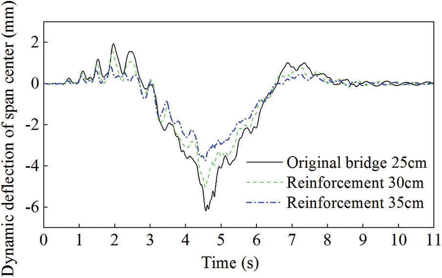
Figure 10: Comparison of the dynamic deflection for Scheme 2
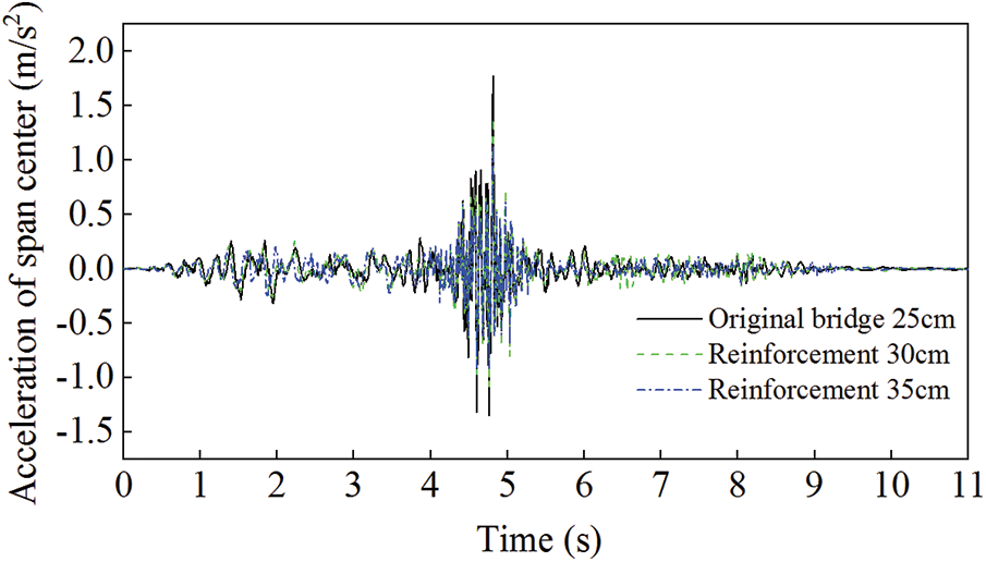
Figure 11: Comparison of the acceleration for Scheme 2
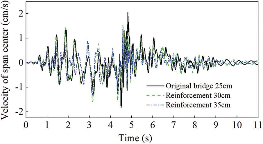
Figure 12: Comparison of the velocity for scheme 2
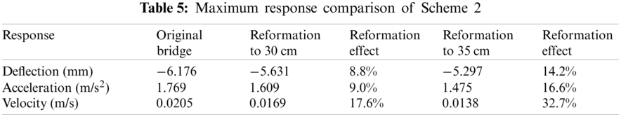
From the comparison, it can be concluded that the reformation of the bridge deck is also relatively effective in reducing the bridge vibration responses, though it is not so significant compared with that of the Addition of longitudinal beam scheme. Reformation of the bridge deck to 35 cm has a better effect than that to 30 cm. It can be confirmed that with the increase of the bridge deck thickness, the vibration reduction effect is also increasing. However, it is necessary to decide the reasonable thickness to be increased in the reformation scheme in the practical use according to various engineering conditions.
4.2.3 Scheme 3--Replacement of Suspenders
This scheme replaces the suspenders by respectively increasing the diameter of suspenders to 0.15 and 0.2 m from original 0.1 m. The dynamic deflection, acceleration, and velocity of the span center of the arch bridge calculated by the developed program are shown in Figs. 13–15, compared with those of the original bridge. The maximum values of the dynamic deflection, acceleration, and velocity of the span center for the two reinforcement plans, compared with those of the original bridge, and their reduction effects, are shown in Table 6.
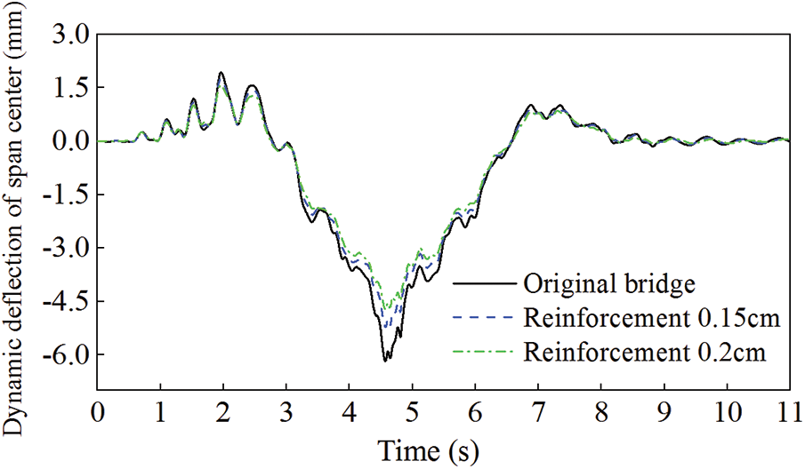
Figure 13: Comparison of the dynamic deflection for Scheme 3
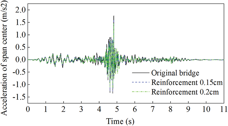
Figure 14: Comparison of the acceleration for Scheme 3
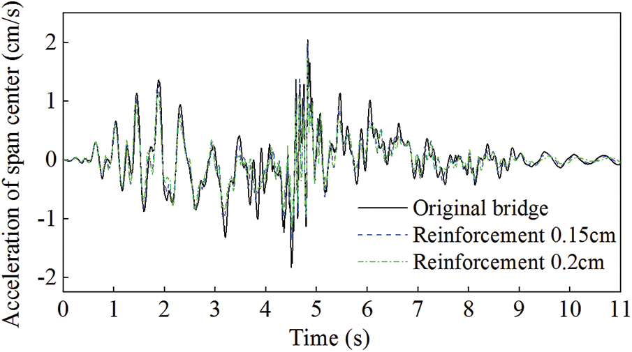
Figure 15: Comparison of the velocity for Scheme 3
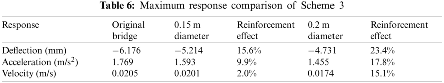
Based on the comparison result, it can be concluded that the suspender's reformation also effectively reduces the dynamic deflection of the span center. However, it has less effect on the acceleration and speed response compared with those of Schemes 1 and 2. Thus, the vibration reduction effect of this scheme is not so significant. On the other hand, in this scheme the increase of the suspender diameter is only a confirmation of its increasing rigidity, and it is complicated to be used in the practice due to the suspender materials, cost and also installation process. Therefore, compared with the previous two schemes, this scheme has no significant merits on bridge vibration reduction, and is not recommended to be adopted in the practical use.
In this study, focusing on the running vehicle-induced vibration problem of the concrete-filled steel tube arch bridges constructed in the past, a numerical analysis program is developed and coded with FORTRAN language, based on the d'Alembert's principle and the finite element method. An accurate dynamic spatial vehicle model and a 3D FE bridge model are established, taking into account the bumping effect and road surface irregularity influence during motion of the vehicle. This program can realize the accurate vehicle-bridge coupled vibration analysis with sophisticated vehicle and bridge models and complicated real conditions.
A continuous half-through concrete-filled steel tube arch bridge with vibration problems completed in Shenyang City, China in July 1997 was the target in this study. With the rapid development of the city and the increase in traffic volume, the bridge structure based on its original design is approaching the carrying capacity limit. Simultaneously, the vibration problem of the bridge deck structure is gradually becoming more and more significant in its actual use due to the design problem and structural deterioration. Therefore, three reinforcement schemes are proposed due to the mechanism of actual deterioration problems, which respectively are Addition of longitudinal beams, Replacement of bridge deck, Replacement of suspenders.
Then, the dynamic deflection, acceleration, and velocity of the bridge span center were calculated respectively for each reinforcement scheme using the vehicle-bridge coupled vibration analysis program developed in this research, and the reinforcement effect of each reinforcement scheme was evaluated and compared. The main findings from the numerical results and comparisons are as follows:
1) In the Addition of longitudinal beams scheme, both two reinforcement methods can significantly reduce the bridge vibration response. The effect of the reinforcement is more significant when the steel-concrete composite longitudinal beams were added than that of the longitudinal steel beams, especially for the dynamic deflection of the span center. It can be concluded that adding steel-concrete composite longitudinal beams is more effective on improving the bridge's longitudinal rigidity and is a more reasonable reinforcement scheme.
2) In the Replacement of bridge deck scheme, it is found that this scheme is also relatively effective in reducing the bridge vibration responses, though it is not so significant compared with that of the Addition of longitudinal beam scheme. With the increase of the bridge deck thickness, the vibration reduction effect is also increasing.
3) In the Replacement of suspenders scheme, the suspender's reformation also effectively reduces the dynamic deflection of the span center. However, it has less effect on the acceleration and speed response. Compared with the previous two schemes, this reformation scheme has no significant merits on bridge vibration reduction, and is not recommended to be adopted in the practical use.
Therefore, it can be confirmed that the reinforcement scheme of Addition of longitudinal beams shows the most significant vibration reduction effect in the proposed three schemes, by improving the overall longitudinal rigidity of the bridge. It is recommended in the engineering practice that the combination of the reinforcement schemes of Addition of longitudinal beams and Replacement of bridge deck can be used to solve the excessive vibration problem of the concrete-filled steel tube arch bridge.
Funding Statement: This work is supported by the Natural Science Foundation Projects of Liaoning Province (2019-ZD-0145).
Conflicts of Interest: The authors declare that they have no conflicts of interest to report regarding the present study.
1. Tan, Y. B., Zhang, Z., Yang, Z. L., Tan, Y. G., Wang, H. L. (2020). Reinforcement method for vibration reduction of suspended deck arch bridge and model test. Journal of the Railway Engineering Society, 37(9), 35–40. DOI 10.16339/j.issn.1006-2106.2020.09.037. [Google Scholar] [CrossRef]
2. Tan, Y. B., Zhang, Z., Wang, H. L., Zhou, S. B. (2021). Gray relation analysis for optimal selection of bridge reinforcement scheme based on fuzzy-AHP weights. Mathematical Problems in Engineering, 2021, 1–8. DOI 10.1155/2021/8813940. [Google Scholar] [CrossRef]
3. Technical code for concrete-filled steel tubular arch bridges (2013). National standard of the People's Republic of China, GB 50923–2013. [Google Scholar]
4. Xia, H., Zhang, N. (2005). Dynamic interaction of vehicle and structure. China: Science Press. [Google Scholar]
5. Willis, R. (1849). Appendix to the report of the commissioners appointed to inquire into the application of iron to railway structures. London, UK: William Clowes and Sons. [Google Scholar]
6. Liu, J., Li, Y. (2014). Development and challenge of the vehicle and highway bridges dynamic interaction. Key Engineering Materials, 574, 135–150. DOI 10.4028/www.scientific.net/KEM.574.135. [Google Scholar] [CrossRef]
7. Tan, G. H., Brameld, G. H., Thambiratnam, D. P. (1998). Development of an analytical model for treating bridge-vehicle interaction. Engineering Structures, 20(1), 54–61. DOI 10.1016/S0141-0296(97)00051-5. [Google Scholar] [CrossRef]
8. Mao, W., Li, T., Wang, T., Zhang, L., Liu, X. (2019). Comparative analysis of vehicle-bridge coupling for different bridge numerical models. IOP Conference Series: Earth and Environmental Science, 371(2), 22086. DOI 10.1088/1755-1315/371/2/022086. [Google Scholar] [CrossRef]
9. Xie, Q., Han, W., Yuan, Y. (2020). Refined vehicle-bridge interaction analysis using incompatible solid finite element for evaluating stresses and impact factors. Advances in Civil Engineering, 2020, 1–15. DOI 10.1155/2020/7032460. [Google Scholar] [CrossRef]
10. Korti, J., Daniel, L. (2015). The comparison between the results of the two-dimensional and 3D models of vehicle bridge interaction. Procedia Engineering, 111, 425–430. DOI 10.1016/j.proeng.2015.07.111. [Google Scholar] [CrossRef]
11. He, X. W., Kawatani, M., Nishiyama, S. (2008). An analytical approach to train-induced site vibration around shinkansen viaducts. Structure and Infrastructure Engineering, 6(6), 689–701. DOI 10.1080/15732470802087799. [Google Scholar] [CrossRef]
12. He, X. W., Kawatani, M., Hayashikawa, T., Matsumoto, T. (2011). Numerical analysis on seismic response of shinkansen bridge-train interaction system under moderate earthquakes. Earthquake Engineering and Engineering Vibration, 10(1), 85–97. DOI 10.1007/s11803-011-0049-1. [Google Scholar] [CrossRef]
13. He, X. W., Noda, Y., Hayashikawa, T., Kawatani, M., Matsumoto, T. (2011). An analytical approach to coupled vibration of curved rationalized girder bridges and running vehicles. Proceedings of the Twelfth East Asia-Pacific Conference on Structural Engineering and Construction, Hong Kong, China. pp. 2906–2915. [Google Scholar]
14. Kraff, R., Penchin, J. (2006). Structural dynamics. USA: Pearson. [Google Scholar]
15. Bowe, C. J., Mullarkey, T. P. (2005). Wheel-rail contact elements incorporating irregularities. Advances in Engineering Software, 36(11), 827–837. DOI 10.1016/j.advengsoft.2005.03.026. [Google Scholar] [CrossRef]
 | This work is licensed under a Creative Commons Attribution 4.0 International License, which permits unrestricted use, distribution, and reproduction in any medium, provided the original work is properly cited. |