| Computer Modeling in Engineering & Sciences |
DOI: 10.32604/cmes.2022.019082
ARTICLE
Deep Learning-Based Automatic Detection and Evaluation on Concrete Surface Bugholes
1School of Management Science and Real Estate, Chongqing University, Chongqing, 400044, China
2CMCU Engineering Co., Ltd., Chongqing, 400039, China
*Corresponding Author: Fujia Wei. Email: weifujia13@163.com
Received: 01 September 2021; Accepted: 05 November 2021
Abstract: Concrete exterior quality is one of the important metrics in evaluating construction project quality. Among the defects affecting concrete exterior quality, bughole is one of the most common imperfections, thus detecting concrete bughole accurately is significant for improving concrete exterior quality and consequently the quality of the whole project. This paper presents a deep learning-based method for detecting concrete surface bugholes in a more objective and automatic way. The bugholes are identified in concrete surface images by Mask R-CNN. An evaluation metric is developed to indicate the scale of concrete bughole. The proposed approach can detect bugholes in an instance level automatically and output the mask of each bughole, based on which the bughole area ratio is automatically calculated and the quality grade of the concrete surfaces is assessed. For demonstration, a total of 273 raw concrete surface images taken by mobile phone cameras are collected as a dataset. The test results show that the average precision (AP) of bughole masks is 90.8%.
Keywords: Defect detection; engineering; concrete quality; deep learning; instance segmentation
Concrete is the most widely used material in civil engineering structures. When the surface of a building is mainly composed of concrete, a high-quality exterior becomes an important factor of construction quality. Among the defects affecting the exterior quality, bughole is the most typical one [1]. A recent questionnaire indicates that the exterior of concrete is as important as cost-performance attributes and workability [2]. Moreover, the consequences of bugholes could be serious if the concrete surfaces are to be painted or the damaged area reaches a certain threshold [3, 4]. Related investigations have shown that bugholes on concrete surfaces affect the subsequent painting construction because these defects need to be filled before painting, which causes additional workload and cost [5]. Therefore, bugholes should be minimized during the construction process to improve the flatness and aesthetics of the concrete structure. Traditional detection methods rely on manual inspection [6, 7], which is considered time-consuming and impractical [8, 9]. An improved method of bughole rating recommended by both the Concrete International Board (CIB) and American Concrete Institute (ACI) suggests comparing the concrete surfaces with reference bughole photo samples. The scales of reference bughole photo samples are illustrated in Fig. 1. However, the effectiveness of this method is affected by both the printed scales of reference samples and the subjectivity of human inspectors [10, 11]. In addition, one surface may have several types of imperfections, hence the effectiveness of reference samples is limited.

Figure 1: The scales of reference bughole photo samples
With the development of image processing technology [8–11], image processing methods have been used in many areas including concrete bridge inspection [12], classification of radar images [13], and so on. To enable the inspectors to use the reference bughole photo samples more objectively, some other studies have proposed image processing techniques to detect and evaluate the distribution of bugholes on concrete surfaces [10, 14]. However, some argue that the accuracy of image processing methods is affected by noise such as illumination, shadows, and combinations of several different surface defects [15, 16]. In recent years, algorithms based on deep learning have achieved excellent progress in the challenge of object detection [17]. Deep learning is a sub-field of machine learning. It uses many levels of non-linear information processing and abstraction for supervised or unsupervised feature learning and representation, classification, and pattern recognition [18]. Compared with traditional machine learning, deep learning aims to automatically extract multi-layer feature representations from data. Its core idea is to use a series of non-linear transformations in a data-driven way to extract features from the original data from low-level to high-level, from specific to abstract, and from general to specific semantics. That is, deep learning has powerful capabilities and flexibility in supporting computer systems to be improved from experience and data. Some researchers have applied deep learning-based models in the construction industry. Related research focuses on the application of deep learning-based object detection algorithms to identify, classify, and locate damages on structural surfaces, such as crack detection [19–24], concrete spalling detection [25, 26], and corrosion detection [27]. Among these research, most studies focus on the use of Convolutional Neural Networks (CNNs) to realize the classification and localization of defects. However, insufficient attention has been paid to the evaluation of concrete surfaces [28].
In line with the above research backgrounds, this paper proposes a deep learning-based method using Mask R-CNN [29] to detect bugholes in concrete surface images and support decision-making for quality improvement. The proposed approach can recognize bugholes at an instance level and output the pixel of each bughole. Moreover, the area ratio of bugholes is automatically calculated to evaluate concrete surfaces.
The overall framework of the proposed bughole detection method is given in Fig. 2. The framework is composed of three stages: 1) database (DB) establishment; 2) establishment of network architecture; 3) bughole detection using trained Mask R-CNN. In the first stage, the camera of a mobile phone is used to acquire images from a fair-faced concrete building under different lighting conditions at distances of 0.1–1.0 m. In the second stage, the instance segmentation framework Mask R-CNN is modified to build an end-to-end bughole recognition model. In the third stage, the performance of the trained Mask R-CNN model is evaluated by the test set, and the recognition results are compared with the CIB reference scale to evaluate the bughole rating on the concrete surface. The detailed implementations are described in this section.

Figure 2: Overall framework of the proposed method
A mobile phone camera captures images in this study. A total of 273 concrete surface images with a resolution of 3,024 × 3,024 pixels are collected. To create a database to train and test the Mask R-CNN-based detection model introduced in this study, the original images with a resolution of 3,024 × 3,024 pixels are cropped to 256 × 256 pixels, and a total of 3,215 images containing bughole are selected to create the datasets. The number of images in the training set is 2,572, and the number of images in the validation set is 643, according to the ratio of the training set:validation set = 4:1 [24]. Image annotation is the core of semantic object image segmentation in computer vision [30]. This study uses the image annotation tool “labelme” to annotate the labels and masks of objects (bugholes) [31]. Examples of annotated images are shown in Fig. 3.

Figure 3: Examples of annotated images
A good model requires a lot of data to train, but it is time-consuming and costly to get new data. To overcome this obstacle, data augmentation is a way to increase the amount of data by random scale, crop, flip, shift, noise, and rotation of existing data. Related studies have shown that data augmentation can improve the generalization ability and robustness of the model [20]. In this study, a rotation approach is adopted to augment data. 500 randomly selected images are preprocessed by rotation before the training process. Fig. 4 shows examples of image modification for data augmentation.
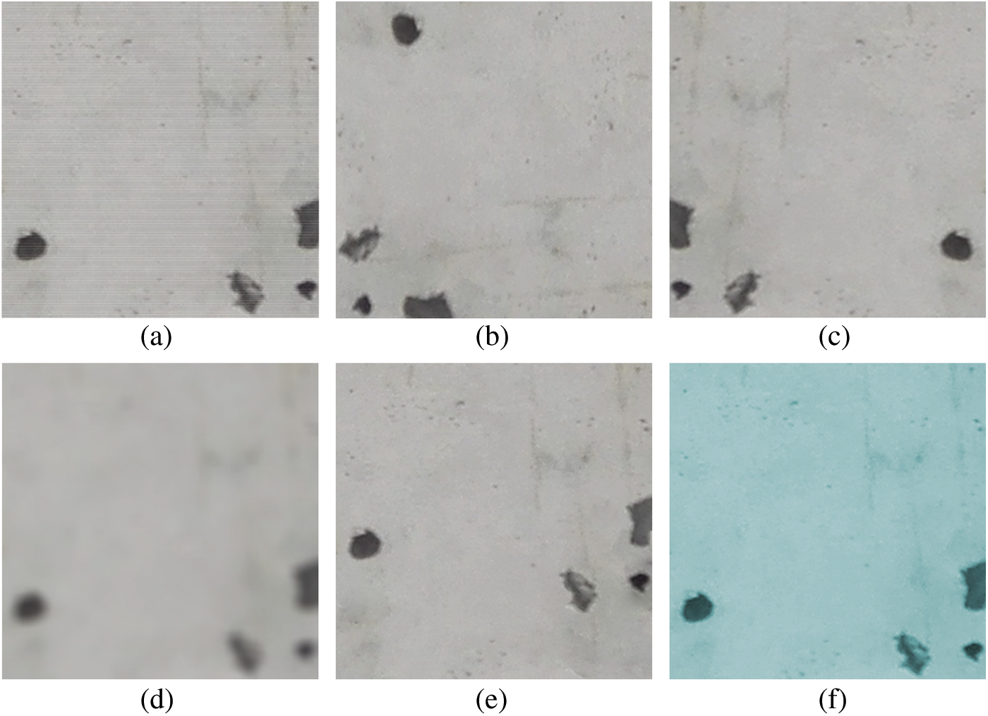
Figure 4: Examples of data augmentation: (a) original image; (b) rotation 90∘ clockwise; (c) flip horizontally; (d) blur; (e) shift; (f) color conversion
2.2 Establishment of Network Architecture
Mask R-CNN is an instance segmentation algorithm. It is a more elaborate segmentation process for similar objects based on semantic segmentation. In this study, the Mask R-CNN algorithm framework performs the task of detecting and evaluating bugholes on concrete surface images. The Residual Network (ResNet) [32] with 101 layers and the Feature Pyramid Network (FPN) [33] are selected as the feature extraction network. The reason for using ResNet is to enrich feature extraction by increasing network depth while addressing the degradation problem. FPN can increase the resolution and high-level semantic information of the feature map, thereby improving the object detection performance of the network. The Region Proposal Network (RPN) selects the candidate Region of Interest (RoI) according to different scales, lengths, and widths, and then distinguishes and initially locates multiple RoIs generated on the feature map. The classic object detection algorithm Faster R-CNN [34] classifies individual bugholes and locates each of them by a bounding box. The classical semantic segmentation algorithm fully convolutional network (FCN) [35] generates the corresponding mask branch, which can distinguish each bughole at the instance level. The overall network architecture of the Mask R-CNN framework is shown in Fig. 5. The specifications of Mask R-CNN without RPN are shown in Table 1. The detailed specification of Conv and identity block with depth (64/64/256) are shown in Table 2.
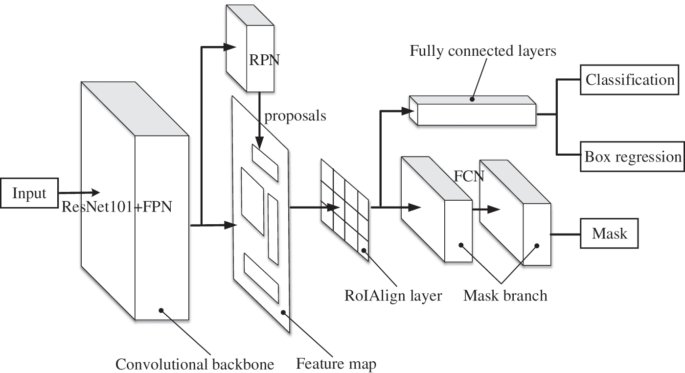
Figure 5: The architecture of Mask R-CNN


Since the added Mask branch needs to extract a finer spatial layout of the object, thus it exposes the pixel deviation problem of RoI Pooling in the Faster R-CNN algorithm. To solve the problem, the corresponding RoI alignment strategy is proposed. RoI alignment cancels the quantization operation, calculates four regular sampling points in each bin, calculates the values of these four positions by bilinear interpolation, and then performs the maximum pooling operation so that the pixel mask generated by FCN can retain accurate spatial location, as shown in Fig. 6. The solid-line grid represents the feature map. The orange blocks represent the RoI. RoI alignment operation does not perform quantization on any coordinates involved in the RoI, bins, or sampling points, thus avoiding the misalignment between the RoI and the extracted features caused by quantization [29].
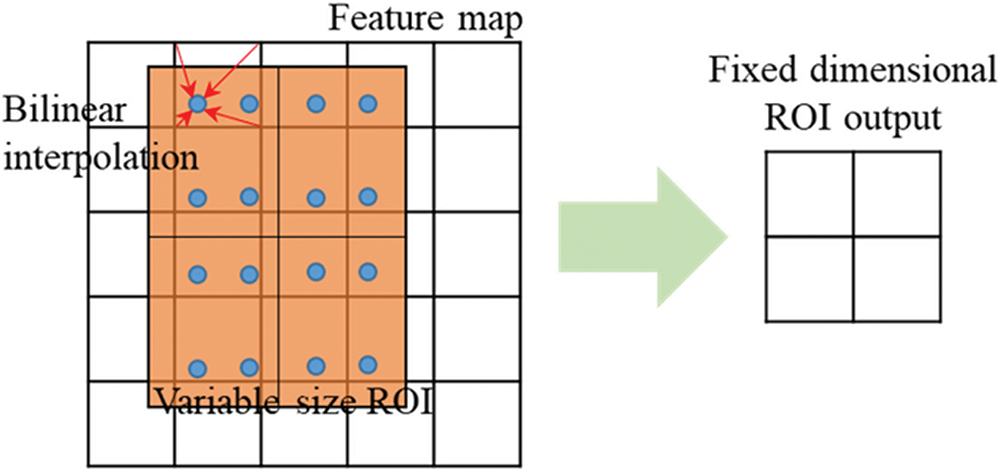
Figure 6: Operation of RoI alignment
In the RoI regression process, to make the predicted object window closer to the ground truth box, bounding-box regression is often used for fine-tuning. For windows, a four-dimensional vector (x, y, w, h) is generally used to represent the center point coordinates, width, and height of the window. As shown in Fig. 7, the blue dashed window P represents the original proposal, and the red window G represents the ground truth of the object. The goal of RoI regression is to find a relationship that maps the input original window P to a regression window closer to the ground truth window G.
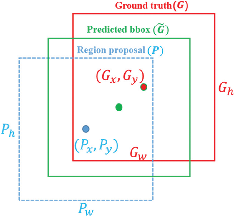
Figure 7: Computation graph of bounding box regression
That is: given P = (Px, Py, Pw, Ph,), find a mapping f such that: .
The transformation of bounding-box regression is as follows:
1) Translate the original proposal window , where and , then Eqs. (1) and (2) are obtained:
2) Scale the original proposal window (Sw, Sh), where Sw = pwdw(p) and Sh = phdh(p), then Eqs. (3) and (4) are obtained:
From the above four equations, the translation and scaling required by the predicted proposal are (dx(p), dy(p), dw(p), dh(p)), where (dx(p), dy(p), dw(p), dh(p)) should be equal to (tx, ty, tw, th) which is translation and scaling required between ground truth window G and original proposal window P, as shown in Eqs. (5) to (8):
Therefore, the objective function can be expressed as , where is the eigenvector of the input proposal; w* T is the parameter to be learned; * represents x, y, w, and h, the objective function corresponding to each transformation; d*(p) represents the coordinates of the prediction window. To minimize the deviation between the prediction window and ground truth window, the loss function is defined in Eq. (9):
(9)
The Mask R-CNN in this study is trained using a joint training strategy. A total of 100 epochs are trained, in which the entire network is trained with 40 epochs, the feature extraction network module uses 40 epochs for training, and 20 epochs are used to fine-tune the network heads. After the network training is completed, the test set and other original images are used to assess the detection performance of the trained Mask R-CNN. The learning curves of training and validation processes are shown in Fig. 8. The GPU and CPU training modes are used to train the network. The specific configuration of the system environment is shown in Table 3.
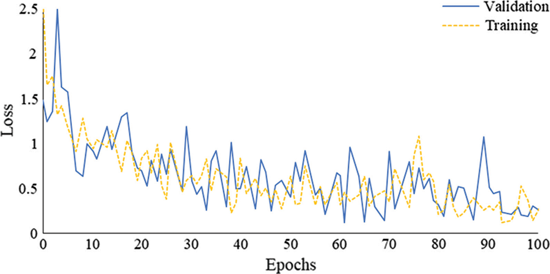
Figure 8: The learning curves of training and validation processes

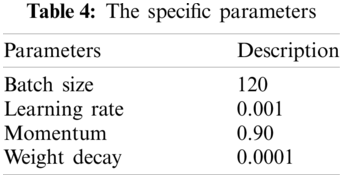
Before starting training, some parameters need to be specified according to the characteristics of the network architecture and training images, such as batch size, learning rate, momentum, and weight decay. The parameters are specified in Table 4. The training time in GPU mode is much shorter than that in CPU mode. It has been estimated that the total training duration in multi-GPU mode is about 0.67 h, while the total training time in CPU mode is more than 12 h. For the same original image with a resolution of 3024 × 3024 pixels, the detection time in GPU mode is 3 s, and the detection time in CPU mode is 60 s.
3.1 Evaluation of the Trained Model
The detection performance of the trained Mask R-CNN model is assessed by Pascal VOC’s metric. The average precision (AP) of both bounding boxes and masks of the test set is tested in the case where Intersection-over-Union (IoU) is set to 0.5 and 0.75, respectively. Fig. 9 illustrates the precision-recall curves of bounding boxes and masks.
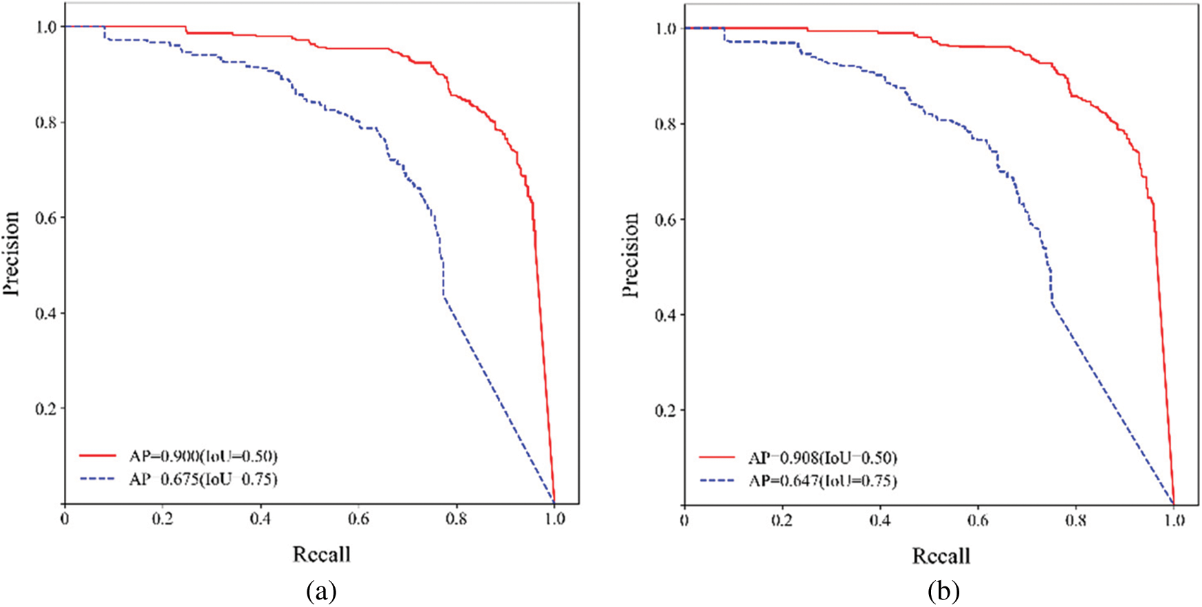
Figure 9: The precision-recall curves (a) bounding-box (b) mask
As can be seen from Fig. 9, different IoU settings affect the average precision of detection. The larger the IoU, the lower the average precision. Conversely, the smaller the IoU, the higher the average precision. In this study, when IoU = 0.5, the average precision of bounding boxes and masks are 0.900 and 0.908, respectively. When IoU = 0.75, the average precision of bounding boxes and masks are 0.675 and 0.647, respectively.
A total of 43 raw images (3,024 × 3,024 pixel resolutions) are used for evaluating the bughole detection performance of the proposed method. The AP of bounding boxes and masks for these raw images is recorded and the mean AP (mAP) is computed, as shown in Figs. 10 and 11.
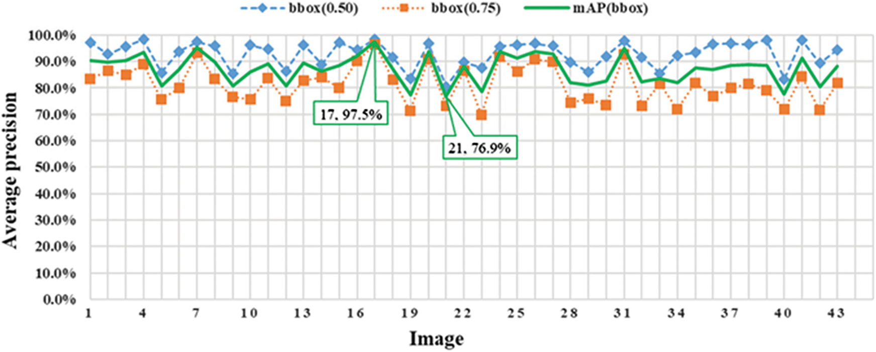
Figure 10: The AP and mAP of bounding boxes
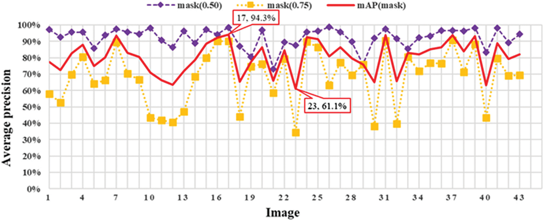
Figure 11: The AP and mAP of masks
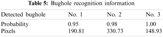
As shown in Figs. 10 and 11, Image 17 has the highest mAP of 97.5% and 94.0% for bounding box and mask, respectively. The bounding box of Image 21 has the lowest AP of 76.9%. The mask of Image 23 has the lowest AP of 61.1%. The AP of both bounding boxes and masks of these 43 images at IoU = 0.5 and IoU = 0.75 are listed in Appendix A. Fig. 12 illustrates the results of bughole detection on concrete surface images by the proposed method. The input is a cropped image with a resolution of 256 × 256 pixels, and the output is the bughole detection result. The first number in the label of the output image represents the probability, and the second number represents the pixel. The bughole recognition results of the sample image in Fig. 12 are listed in Table 5.

Figure 12: The input and output images
3.3 Evaluation of Bugholes on Concrete Surfaces
Inspired by the CIB bughole rating method, by calculating the percentage of bughole area in the concrete surface image, the surface bugholes of concrete are divided into seven levels. With the aid of the image processing tool, the analysis result of the CIB bughole scale is shown in Fig. 13.
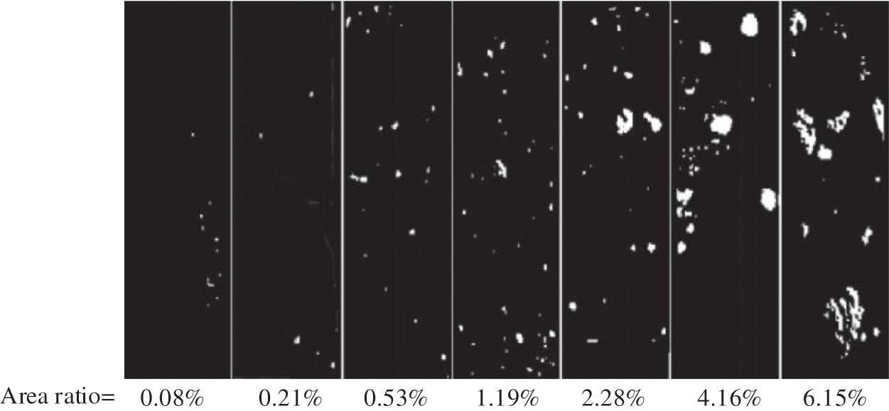
Figure 13: The result of the CIB bughole scale obtained by image processing
The relationship between the area ratio of surface bugholes and the CIB bughole scale is obtained and shown in Fig. 14. The regression analysis equation of the area ratio and CIB bughole scale is shown in Eq. (10):
where Ab is the percentage of surface bugholes in the image to be rated and R represents the regression coefficient.
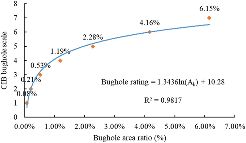
Figure 14: Relation between area ratio of surface bugholes and CIB bughole scale
According to the CIB classification and the regression analysis equation of the area ratio and CIB bughole scale, the recommended rating of bughole in this study is shown in Table 6.

The proposed method can output the pixels of each bughole, and the area ratio of surface bugholes is calculated by dividing the number of pixels in detected bugholes by the total number of pixels of the image. The final output layer is designed to directly output the calculated area ratio of the bugholes and a bughole rating by automatically comparing the recommended bughole scale shown in Table 6. Fig. 15 illustrates some examples of bughole evaluation of concrete surfaces by the proposed method.
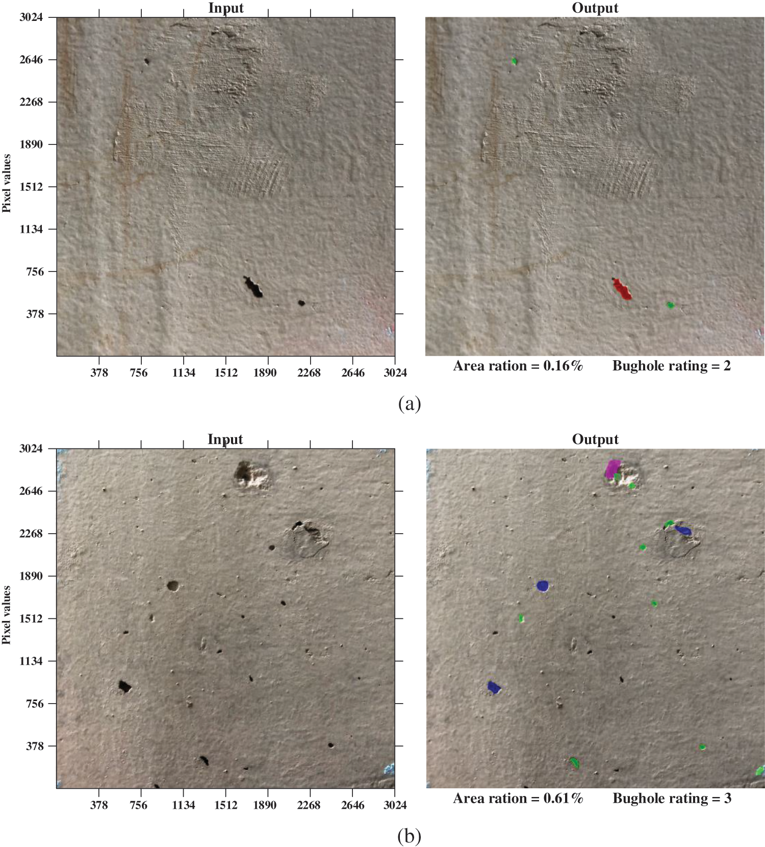
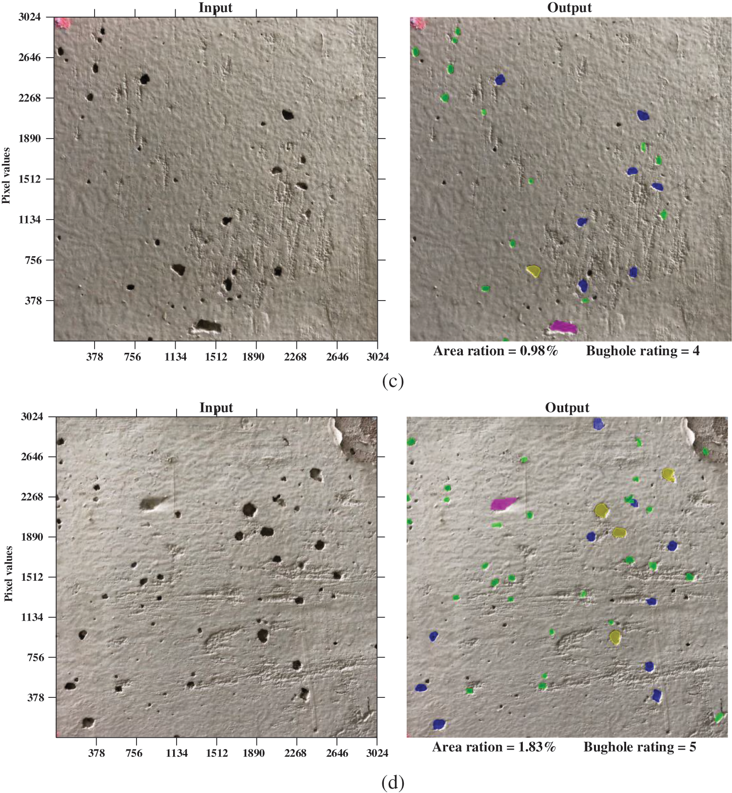
Figure 15: Examples of bughole evaluation of concrete surfaces by the proposed method: (a) bughole rating is 2; (b) bughole rating is 3; (c) bughole rating is 4; (d) bughole rating is 5
The above analysis demonstrates that the evaluation method introduced in this study ensures better accuracy in detecting bugholes of concrete surfaces, which in turn provides better data for the improvement of concrete quality. The performance of the introduced bughole evaluation method is compared with that of the other three algorithms, namely Faster R-CNN, Retinanet, and FCN. The results are shown in Table 7.
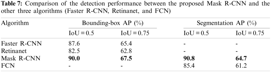
As shown in Table 7, Faster R-CNN has a bounding box AP of 87.6% and 65.4% at IoU = 0.5 and IoU = 0.75, respectively. Retinanet has a bounding box AP of 82.5% and 62.8% at IoU = 0.5 and IoU = 0.75, respectively. Mask R-CNN has a bounding box AP of 90.0% and 67.5% at IoU = 0.5 and IoU = 0.75, respectively. To compare with the traditional CNN-based object detection algorithm, Fig. 16 shows the recognition results of the same bughole image under different algorithms. As shown in the results, bounding boxes can locate bugholes well, however, they are unable to identify the contours of the bugholes. Therefore, the surface bughole detection and evaluation methods based on object detection algorithms are not accurate enough. In contrast, Mask R-CNN outputs the instance segmentation mask while locating the bughole, which enables further quantification and evaluation. The test results in Table 7 show that the segmentation AP of Mask R-CNN at IoU = 0.5 and IoU = 0.75 is 90.8% and 64.7%, respectively. The segmentation AP of FCN at IoU = 0.5 and IoU = 0.75 is 85.4% and 61.2%, respectively. It is considered reasonable to choose the Mask R-CNN framework based on the instance segmentation algorithm for bughole identification and evaluation.
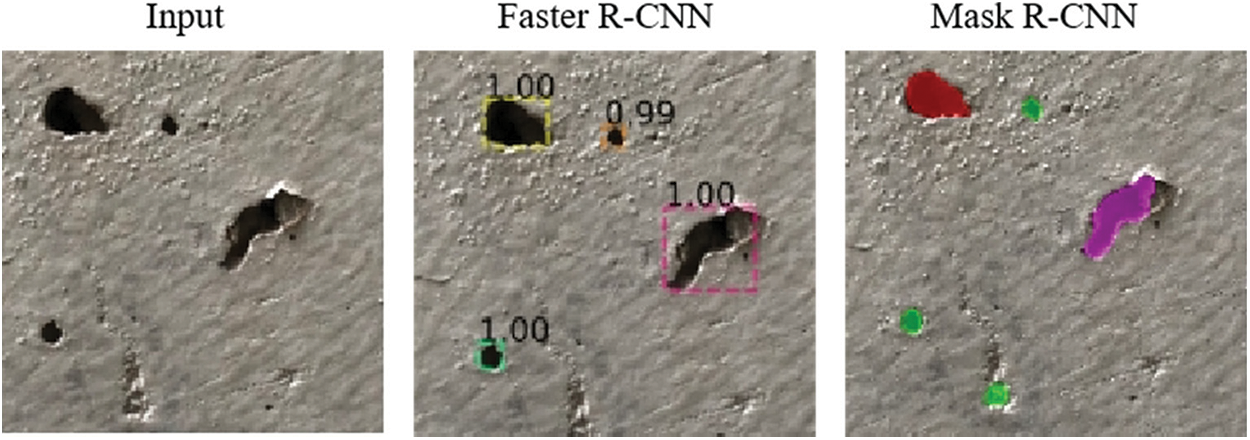
Figure 16: Recognition results of Faster R-CNN and Mask R-CNN
The application of the proposed method in detecting bugholes may still misidentify other surface defects as bugholes (i.e., false-positive results). For example, a spalling is misidentified as a bughole, as shown in the red box in Fig. 17. Such false-positive results will affect the accuracy of concrete quality evaluation.
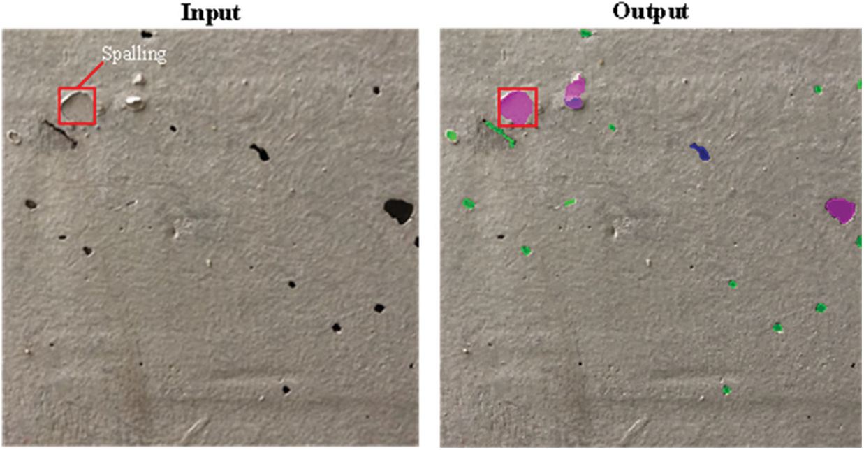
Figure 17: Detection result of an example image containing bughole and spalling
Concrete surface quality control is one of the keys in construction project management. The detection and evaluation of concrete surface bugholes are among the main tasks in implementing concrete quality control. Traditionally, project managers and inspectors mainly rely on human visual methods to evaluate the surface quality of concrete, which is subjective and inefficient. To mitigate these weaknesses, this paper has introduced a deep learning-based automatic instance-level evaluation method for detecting concrete surface bugholes more objectively and automatically.
The analysis in the paper suggests that Mask R-CNN-based method prevails over traditional methods for analyzing concrete quality in several aspects. Firstly, it improves the objectivity of the evaluation process. The method presented in this paper uses images as the basis for evaluation. A total of 273 concrete surface photos are collected to build a data set, and then image recognition technology based on deep learning replaces human eyes for detection and evaluation, which significantly improves the objectivity of evaluation. Secondly, the accuracy of detection is improved. The bughole detection model based on Mask R-CNN can identify the contours of bugholes effectively, and output the mask of each bughole instead of a bounding box so that the actual area of the bughole on the concrete surface can be calculated more accurately. The test results show that the average precision (AP) of bughole masks reaches 90.8%. Thirdly, the introduced method can provide better data for improving the quality of concrete. The method presented in this paper can recognize bugholes at an instance level and output the pixels of each bughole, and the area ratio of bugholes is automatically calculated, which in turn can provide better decision-making data about the quality of concrete surfaces.
Despite the excellent performance of the proposed method, it still has limitations in detecting bugholes due to the interference of other imperfections, such as spalling. It is recommended to develop detection and quantification methods for multiple damage types based on deep learning to establish a more comprehensive evaluation model for concrete exterior quality.
Funding Statement: This work is supported by Chongqing Municipal Natural Science Foundation (Grant Nos. cstc2021jcyj-bsh0189 and cstc2019jcyj-bshX0070) and Chongqing Jiulongpo District Science and Technology Planning Project (Grant No. 2020–01–001-Y).
Conflicts of Interest: The authors declare that they have no conflicts of interest to report regarding the present study.
1. Wei, W., Ding, L., Luo, H., Li, C., Li, G. et al. (2021). Automated bughole detection and quality performance assessment of concrete using image processing and deep convolutional neural networks. Construction and Building Materials, 281, 122576. DOI 10.1016/j.conbuildmat.2021.122576. [Google Scholar] [CrossRef]
2. Yoshitake, I., Maeda, T., Hieda, M. (2018). Image analysis for the detection and quantification of concrete bugholes in a tunnel lining. Case Studies in Construction Materials, 8, 116–130. DOI 10.1016/j.cscm.2018.01.002. [Google Scholar] [CrossRef]
3. Kalayci, A. S., Yalim, B., Mirmiran, A. (2009). Effect of untreated surface disbonds on performance of FRP-retrofitted concrete beams. Journal of Composites for Construction, 13(6), 476–485. DOI 10.1061/(asce)cc.1943-5614.0000032. [Google Scholar] [CrossRef]
4. Ichimiya, K., Idemitsu, T., Yamasaki, T. (2002). The influence of air content and fluidity of mortar on the characteristics of surface voids in self-compacting concrete. Doboku Gakkai Ronbunshu, 56(711), 135–146. DOI 10.2208/jscej.2002.711_135. [Google Scholar] [CrossRef]
5. Wei, F., Yao, G., Yang, Y., Sun, Y. (2019). Instance-level recognition and quantification for concrete surface bughole based on deep learning. Automation in Construction, 107(174), 1–13. DOI 10.1016/j.autcon.2019.102920. [Google Scholar] [CrossRef]
6. Lemaire, G., Escadeillas, G., Ringot, E. (2005). Evaluating concrete surfaces using an image analysis process. Construction and Building Materials, 19, 604–611. DOI 10.1016/j.conbuildmat.2005.01.025. [Google Scholar] [CrossRef]
7. Coster, M., Chermant, J. (2001). Image analysis and mathematical morphology for civil engineering materials. Cement and Concrete Composites, 23, 133–151. DOI 10.1016/S0958-9465(00)00058-5. [Google Scholar] [CrossRef]
8. Chermant, J. (2001). Why automatic image analysis ? An introduction to this issue. Cement & Concrete Composites, 23, 127–131. DOI 10.1016/S0958-9465(00)00077-9. [Google Scholar] [CrossRef]
9. Lee, S., Chang, L., Skibniewski, M. (2006). Automated recognition of surface defects using digital color image processing. Automation in Construction, 15(4), 540–549. DOI 10.1016/j.autcon.2005.08.001. [Google Scholar] [CrossRef]
10. Liu, B., Yang, T. (2017). Image analysis for detection of bugholes on concrete surface. Construction and Building Materials, 137, 432–440. DOI 10.1016/j.conbuildmat.2017.01.098. [Google Scholar] [CrossRef]
11. Laofor, C., Peansupap, V. (2012). Defect detection and quantification system to support subjective visual quality inspection via a digital image processing: A tiling work case study. Automation in Construction, 24, 160–174. DOI 10.1016/j.autcon.2012.02.012. [Google Scholar] [CrossRef]
12. Silva, W. R. L. D., Štemberk, P. (2013). Expert system applied for classifying self-compacting concrete surface finish. Advances in Engineering Software, 64, 47–61. DOI 10.1016/j.advengsoft.2013.04.005. [Google Scholar] [CrossRef]
13. Ince, T. (2010). Unsupervised classification of polarimetric SAR image with dynamic clustering: An image processing approach. Advances in Engineering Software, 41(4), 636–646. DOI 10.1016/j.advengsoft.2009.12.004. [Google Scholar] [CrossRef]
14. Ozkul, T., Kucuk, I. (2011). Design and optimization of an instrument for measuring bughole rating of concrete surfaces. Journal of the Franklin Institute, 348(7), 1377–1392. DOI 10.1016/j.jfranklin.2010.04.004. [Google Scholar] [CrossRef]
15. Khireddine, A., Benmahammed, K., Puech, W. (2007). Digital image restoration by wiener filter in 2D case. Advances in Engineering Software, 38(7), 513–516. DOI 10.1016/j.advengsoft.2006.10.001. [Google Scholar] [CrossRef]
16. Yao, G., Wei, F., Yang, Y., Sun, Y. (2019). Deep-learning-based bughole detection for concrete surface image. Advances in Civil Engineering, 2019. DOI 10.1155/2019/8582963. [Google Scholar] [CrossRef]
17. Krizhevsky, A., Sutskever, I., Hinton, G. E. (2012). ImageNet classification with deep convolutional neural networks. Communications of the ACM, 60(6), 84–90. DOI 10.1145/3065386. [Google Scholar] [CrossRef]
18. Deng, L., Yu, D. (2013). Deep learning: Methods and applications. Foundations and Trends in Signal Processing, 7(3), 197–387. DOI 10.1561/2000000039. [Google Scholar] [CrossRef]
19. Tedeschi, A., Benedetto, F. (2017). A Real-time automatic pavement crack and pothole recognition system for mobile android-based devices. Advanced Engineering Informatics, 32, 11–25. DOI 10.1016/j.aei.2016.12.004. [Google Scholar] [CrossRef]
20. Cha, Y. J., Choi, W., Suh, G., Mahmoudkhani, S., Büyüköztürk, O. (2017b). Autonomous structural visual inspection using region-based deep learning for detecting multiple damage types. Computer-Aided Civil and Infrastructure Engineering, 33(9), 731–747. DOI 10.1111/mice.12334. [Google Scholar] [CrossRef]
21. Chen, F. C., Jahanshahi, M. R. (2018). NB-CNN: Deep learning-based crack detection using convolutional neural network and naive Bayes data fusion. IEEE Transactions on Industrial Electronics, 65(5), 4392–4400. DOI 10.1109/TIE.2017.2764844. [Google Scholar] [CrossRef]
22. Wang, K. C. P., Zhang, A., Li, J. Q., Fei, Y. (2017). Deep learning for asphalt pavement cracking recognition using convolutional neural network. International Conference on Highway Pavements and Airfield Technology, pp. 166–177. Philadelphia, USA. [Google Scholar]
23. Cireşan, D., Meier, U., Masci, J., Schmidhuber, J. (2012). Multi-column deep neural network for traffic sign classification. Neural Networks, 32, 333–338. DOI 10.1016/j.neunet.2012.02.023. [Google Scholar] [CrossRef]
24. Cha, Y. J., Choi, W., Büyüköztürk, O. (2017a). Deep learning-based crack damage detection using convolutional neural networks. Computer-Aided Civil and Infrastructure Engineering, 32(5), 361–378. DOI 10.1111/mice.12263. [Google Scholar] [CrossRef]
25. Cui, X., Wang, Q., Dai, J., Zhang, R., Li, S. (2021). Intelligent recognition of erosion damage to concrete based on improved YOLO-v3. Materials Letters, 302, 1–4. DOI 10.1016/j.matlet.2021.130363. [Google Scholar] [CrossRef]
26. Shin, H. K., Lee, S. W., Hong, G. P., Sael, L., Lee, S. H. et al. (2020). Defect-detection model for underground parking lots using image object-detection method. Computers, Materials and Continua, 66(3), 2493–2507. DOI 10.32604/cmc.2021.014170. [Google Scholar] [CrossRef]
27. Atha, D. J., Jahanshahi, M. R., (2018). Evaluation of deep learning approaches based on convolutional neural networks for corrosion detection. Structural Health Monitoring, 17, 1110–1128. DOI 10.1177/1475921717737051. [Google Scholar] [CrossRef]
28. Koch, C., Georgieva, K., Kasireddy, V., Akinci, B., Fieguth, P. (2015). A review on computer vision based defect detection and condition assessment of concrete and asphalt civil infrastructure. Advanced Engineering Informatics, 29(2), 196–210. DOI 10.1016/j.aei.2015.01.008. [Google Scholar] [CrossRef]
29. He, K., Gkioxari, G., Dollar, P., Girshick, R. (2017). Mask R-CNN. Proceedings of the IEEE International Conference on Computer Vision, pp. 2980–2988. Venice, Italy. [Google Scholar]
30. Yang, X., Chen, R., Zhang, F. (2021). Pixel-level automatic annotation for forest fire image. Engineering Applications of Artificial Intelligence, 104, 1–14. DOI 10.1016/j.engappai.2021.104353. [Google Scholar] [CrossRef]
31. Bhagat, P. K., Choudhary, P. (2018). Image annotation: then and now. Image and Vision Computing, 80, 1–23. DOI 10.1016/j.imavis.2018.09.017. [Google Scholar] [CrossRef]
32. He, K., Zhang, X., Ren, S., Sun, J. (2016). Deep residual learning for image recognition. IEEE Conference on Computer Vision and Pattern Recognition, pp. 770–778. Las Vegas, USA. [Google Scholar]
33. Lin, T. Y., Dollár, P., Girshick, R., He, K., Hariharan, B. (2017). Feature pyramid networks for object detection. 30th IEEE Conference on Computer Vision and Pattern Recognition, pp. 936–944. Hawaii, USA. [Google Scholar]
34. Ren, S., He, K., Girshick, R., Sun, J. (2017). Faster R-CNN: Towards real-time object detection with region proposal networks. IEEE Transactions on Pattern Analysis and Machine Intelligence, 39(6), 1137–1149. DOI 10.1109/TPAMI.2016.2577031. [Google Scholar] [CrossRef]
35. Shelhamer, E., Long, J., Darrell, T. (2017). Fully convolutional networks for semantic segmentation. IEEE Transactions on Pattern Analysis and Machine Intelligence, 39(4), 640–651. DOI 10.1109/TPAMI.2016.2572683. [Google Scholar] [CrossRef]
6.1 Appendix A: The APs of both bounding box and mask

 | This work is licensed under a Creative Commons Attribution 4.0 International License, which permits unrestricted use, distribution, and reproduction in any medium, provided the original work is properly cited. |