| Computer Modeling in Engineering & Sciences |
DOI: 10.32604/cmes.2022.019835
ARTICLE
Time-Variant Reliability-Based Multi-Objective Fuzzy Design Optimization for Anti-Roll Torsion Bar of EMU
1Yangtze Delta Region Institute (Huzhou), University of Electronic Science and Technology of China, Huzhou, 313001, China
2School of Mechanical and Electrical Engineering, University of Electronic Science and Technology of China, Chengdu, 611731, China
3School of Mechanical Engineering, Dalian Jiaotong University, Dalian, 116028, China
4Hefei CRRC Rolling Stock Co., Ltd., Hefei, 230012, China
*Corresponding Author: Zhonglai Wang. Email: wzhonglai@uestc.edu.cn
Received: 19 October 2021; Accepted: 05 November 2021
Abstract: Although various types of anti-roll torsion bars have been developed to inhibit excessive roll angle of the electric multiple unit (EMU) car body, it is critical to ensure the reliability of structural design due to the complexity of the problems involving time and uncertainties. To address this issue, a multi-objective fuzzy design optimization model is constructed considering time-variant stiffness and strength reliability constraints for the anti-roll torsion bar. A hybrid optimization strategy combining the design of experiment (DoE) sampling and non-linear programming by quadratic lagrangian (NLPQL) is presented to deal with the design optimization model. To characterize the effect of time on the structural performance of the torsion bar, the continuous-time model combined with Ito lemma is proposed to establish the time-variant stiffness and strength reliability constraints. Fuzzy mathematics is employed to conduct uncertainty quantification for the design parameters of the torsion bar. A physical programming approach is used to improve the designer's preference and to make the optimization results more consistent with engineering practices. Moreover, the effectiveness of the proposed method has been validated by comparing with current methods in a practical engineering case.
Keywords: Anti-roll torsion bar; time-variant reliability; fuzzy design optimization; multi-objective
Reliability-based design optimization (RBDO) is an important way to improve the reliability of products under uncertainty in the design stage. Due to the time-variant property of design parameters, working conditions and uncertainties affecting the products’ performance, time-variant reliability-based design optimization (TRBDO) has become urgent to ensure the operating reliability and safety during the products’ lifecycle. Currently, TRBDO has attracted more attentions and is being applied in engineering practices [1–4].
For a complicated engineering problem, one main challenging task is to build the TRBDO model sufficiently considering the complexity of the working conditions and uncertainty quantification as well as the nested relationship between objectives and constraints. In addition, several objectives should be balanced and therefore the multi-objective optimization should be performed during the procedure of the TRBDO. So far, there are several preliminary developments by integrating the TRBDO and the multi-objective optimization, which will be one of the important trend of the design technique under uncertainty. Multidisciplinary design optimization (MDO) mainly focus on the coupled relationship between different disciplines or subsystems [5–11], while multi-objective optimization makes a decision by balancing the objectives under the satisfaction of constraints [12–14]. In some special cases, the MDO problem can be transformed to the multi-objective optimization problem. Therefore, time-variant reliability-based multi-objective design optimization (TRBMDO) is a necessary approach to guaranteeing the lifecycle reliability and safety of products while the balance of several objectives and other constraints are satisfied. Currently, several methods have been developed for the TRBMDO. Yu et al. [15] proposed a multi-objective design optimization framework combining both the time-variant reliability and robustness. Zhang et al. [16] implemented the multi-objective optimization model for the lifting gear transmission system, where the distance between natural frequency and meshing frequency is maximized and the volume of gears is minimized under the time-variant reliability constraints. Dong et al. [17] studied the multi-objective optimization by considering the deterioration of the bridge with the time progressing under uncertainty. Okasha et al. [18] discussed the time-variant redundancy of structural systems and provided the multi-objective optimization framework for the risk-based management. Wang et al. [19] employed a nested extreme response surface to conduct the multi-objective optimization in an iterative RBRDO process with the lifecycle cost and the quality of aircraft tubing as the design objectives. Angelis et al. [20] gave the general and effective numerical method for a fatigue-prone weld to achieve the robust and time-variant maintenance plan.
For the structure of EMU, the secondary suspension system usually uses the air spring to obtain better vertical performance and improve the riding comfort. However, the low stiffness of the air spring will lead to the reduction of the roll stiffness of the vehicle and then the roll angle increases. Especially when the vehicle is operating on the curve track with superelevation, or when the vehicle encounters a large lateral wind, the smaller roll stiffness will raise the operating risk greatly. In order to address the issue well, the anti-rolling device is used to increase the counter-torque against the lateral rolling of the vehicle body. The overturning safety is then improved by reducing the inclination angle of the vehicle without increasing the vertical stiffness of the spring. As the most part of the anti-rolling device, the time-variant reliability of the anti-roll torsion bar will directly affect the operating safety of the vehicle.
However, many studies are about the stiffness and strength analysis under the time-invariant conditions as well as the fatigue experiments for the anti-roll torsion bar. Duan et al. [21] presented a calculation model for the deformation and stress considering the different loading state of the anti-roll torsion bar system. Lu et al. [22] described the stress and load-bearing state of the anti-roll torsion bar for the operating vehicle and then carried out the fatigue life analysis and experimental verification. Wang et al. [23] discussed the influence of velocity, the curve radius, and the superelevation on the anti-roll torsion bar according to the loading history. Dong et al. [24] provided a multi-response robust optimization method for the anti-roll torsion bar based on a stochastic model. However, the time-variant reliability of the anti-roll torsion bar has been rarely investigated.
In this paper, a time-variant reliability-based multi-objective fuzzy design optimization (TRBMFDO) method for the anti-roll torsion bar of the EMU is proposed. The TRBDO constraints related to the stiffness and strength are first established by accounting for the time-variant stochastic working conditions and the working principle of the anti-rolling torsion bar. The optimal rage of design variables is then determined by employing the membership function combined with the fuzzy allowable interval. The physical programming method is then presented to transform the multi-objective fuzzy design optimization problem to a single-objective design optimization problem under the satisfaction of the reliability constraints. The results of the TRBMFDO are finally achieved by using the combinatorial optimization strategy.
The remainder of the paper is organized as follows. Mechanical performance analysis of the torsion bar are presented in Section 2. Time-variant reliability model under the stochastic process is described in detail in Section 3. Section 4 proposes the fuzzy optimization model of the anti-roll torsion bar. Section 5 uses an engineering example to illustrate the effectiveness of the proposed method. Finally, Section 6 summarizes and concludes.
2 Mechanical Performance Analysis of the Torsion Bar
The mechanical performance analysis of the torsion bar is the foundation of the design optimization. Basically, the anti-roll torsion bar can be divided into the built-in bar and external bar according to the different position of the support seat. The support seat of the built-in anti-roll torsion bar is generally composed of the upper part and lower part, where the rubber joint is used. The support seat of the external anti-roll torsion bar is an entire structure, where the metal joint or integral polymer wear-resistant bushing is used. In the paper, we will study the external anti-roll torsion bar, whose installation position in the bogie frame is shown in Fig. 1.
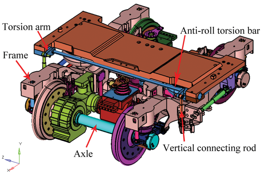
Figure 1: Anti-roll torsion bar device of EMU
2.1 Stiffness Analysis of the Torsion Bar
As the most important performance index of the anti-roll torsion bar device, anti-roll stiffness can ensure the roll angle of the vehicle body and the flexibility coefficient of the vehicle. Proper anti-roll stiffness can effectively improve the safety, stability, and comfort of operation. The anti-roll stiffness can be derived from the force analysis shown in Fig. 2 by considering the installation position and working principle of the anti-roll torsion bar in Fig. 2.
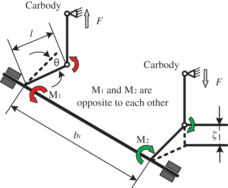
Figure 2: Force diagram of the anti-roll torsion bar device
For the given parameters in Fig. 2, F is the axial force of the connecting rod, θ is the roll angle of the vehicle body,
Considering the working principle of the anti-roll torsion bar, the restoring moment can be expressed as
where
Therefore, the anti-roll stiffness of the torsion bar can be derived by
The torsion bar includes three areas, namely the working area, transition area, and connection area. Therefore, the stiffness of the bar is integrated by the stiffness of the working area, transition area, and connection area. Provided that the cross-section of the torsion bar is circular and its diameter is d, the torsion stiffness can be expressed by
where i is the number of the areas;
When the transition area is an arc, the length of the transition section can be provided by [25]:
where D and d represent the large diameter and small diameter at the transition of the arc, respectively; r represents the radius of the transition arc.
Considering the relationship of the stiffness between the torsion bar and the three areas, the torsional stiffness of the torsion bar is
2.2 Strength Analysis of the Torsion Bar
When the anti-roll torsion bar is operating, it will suffer from the bending stress and torsion shear stress. Generally, the torsion shear stress is greater than the bending stress. The strength of the bar can be derived with the help of the third strength theory by combining the bending stress and torsion shear stress, where the bending moment and torque are shown in Fig. 3.
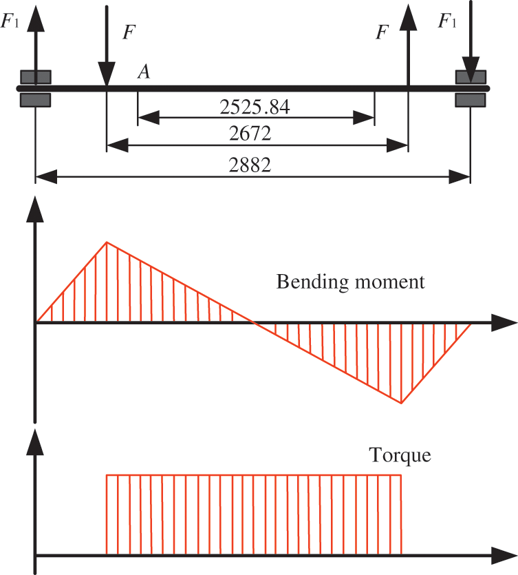
Figure 3: Bending moment and torque diagram of the torsion bar
From Fig. 3, we can see that the torsion bar is only subject to torque in the working area but subject to the bending moment and torque at the same time in the transition and connection areas. For the torsion bar without defect, the maximum stress appears at the crossing of the minimum section transitions.
With the combination of the bending and shear conditions, the stress of the torsion bar is therefore expressed by
3 Time-Variant Reliability Model under the Stochastic Process
The stiffness, strength, and allowable stress of the anti-roll torsion bar are usually time-variant due to several uncertain factors from the working conditions, loadings and also the degradation of the material. The time-variant factors will result in the time-variant change of the reliability of the bar. If the time-variant property is ignored, the reliability only ensure the safety of the bar at the initial time, namely t = 0 not the whole lifecycle. Therefore, it is necessary to properly account for the time-variant property and further conduct TRBDO to guarantee the lifecycle reliability and safety.
3.1 Statistical Analysis for the Stiffness of the Torsion Bar
Since the diameter d changes with time due to the wear, the normal distribution geometric Brownian motion will be employed to describe d(t) under uncertainty. Here, Ito differential equation will be used for featuring the uncertainty propagation based on Eq. (6)
Mean and variance of
Based on Eqs. (8) and (13), the means of
Based on Eqs. (5) and (14), the mean of
3.2 Statistical Analysis for the Strength of the Torsion Bar
Provided E is time-variant under uncertainty and also follows the normal distribution geometric Brownian motion, we have
Take the logarithm of the function according to Eq. (9):
Mean and variance of
3.3 Statistical Analysis for the Material Strength
The material strength of the anti-roll torsion bar is random and time-variant, and therefore non-stationary random process can be employed to describe the material strength. The material strength of the torsion bar can be quantified as the product of the initial material strength and attenuation function.
where
Then the material strength can be expressed with the given expression of the attenuation function
where k is the attenuation coefficient of the material strength.
Mean and variance of
3.4 Time-Variant Reliability of the Anti-Roll Torsion Bar
According to the time-variant stress-strength interference (SSI) model, the reliability of the anti-roll torsion bar can be expressed by [26,27]
We define
Since
The time-variant reliability of the torsion bar is the provided by
4 Fuzzy Optimization Model of the Anti-Roll Torsion Bar
4.1 Physical Programming Model
Physical programming is an effective approach to dealing with the multi-objective optimization problem, since the designer can express his preferences according to the experience. Actually, there are four kinds of preference function, namely Class 1S, Class 2S, Class 3S, and Class 4S, to quantify the designer's requirements [28]. For the anti-roll torsion bar, we mainly focus on the lightweight and high reliability. Therefore, the reference function that the smaller the mass and structural stress the better will be chosen, which belongs to Class 1S and shown in Fig. 4.
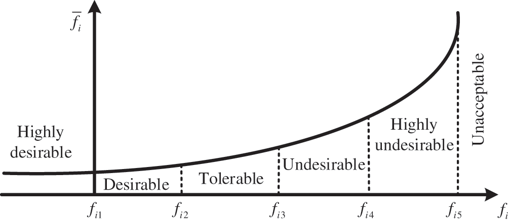
Figure 4: Preference functions for Class 1S
In Fig. 4, i represents the number of design objectives,
where
where
The quantitative preference function can be obtained with the piecewise function curve fitting method based on Eqs. (27)–(34). The preference function of each design objective is further taken into the common logarithm of the average value and synthesized into the comprehensive preference function with
where
4.2 Membership Function of the Fuzzy Constraint and Non-Fuzzy Processing
Due to the existence of incomplete information, fuzzy variable is used to describe the uncertainty of the design variables. It is important to select the proper membership function for the fuzzy variables, since the shape of the membership function will affect the design optimization results. According to the boundary constraint of the design variables, the linear membership function is usually used and provided by
where
The upper and lower limits of the upper and lower bounds in Eq. (36) are determined by the expansion coefficient method, which is widely used in engineering practices. The upper and lower limits of the transition interval are determined by introducing an amplification coefficient. Therefore, the range of the expansion coefficient can be determined as
The framework of the proposed TRBMFDO method of the anti-roll torsion bar is shown in Fig. 5.
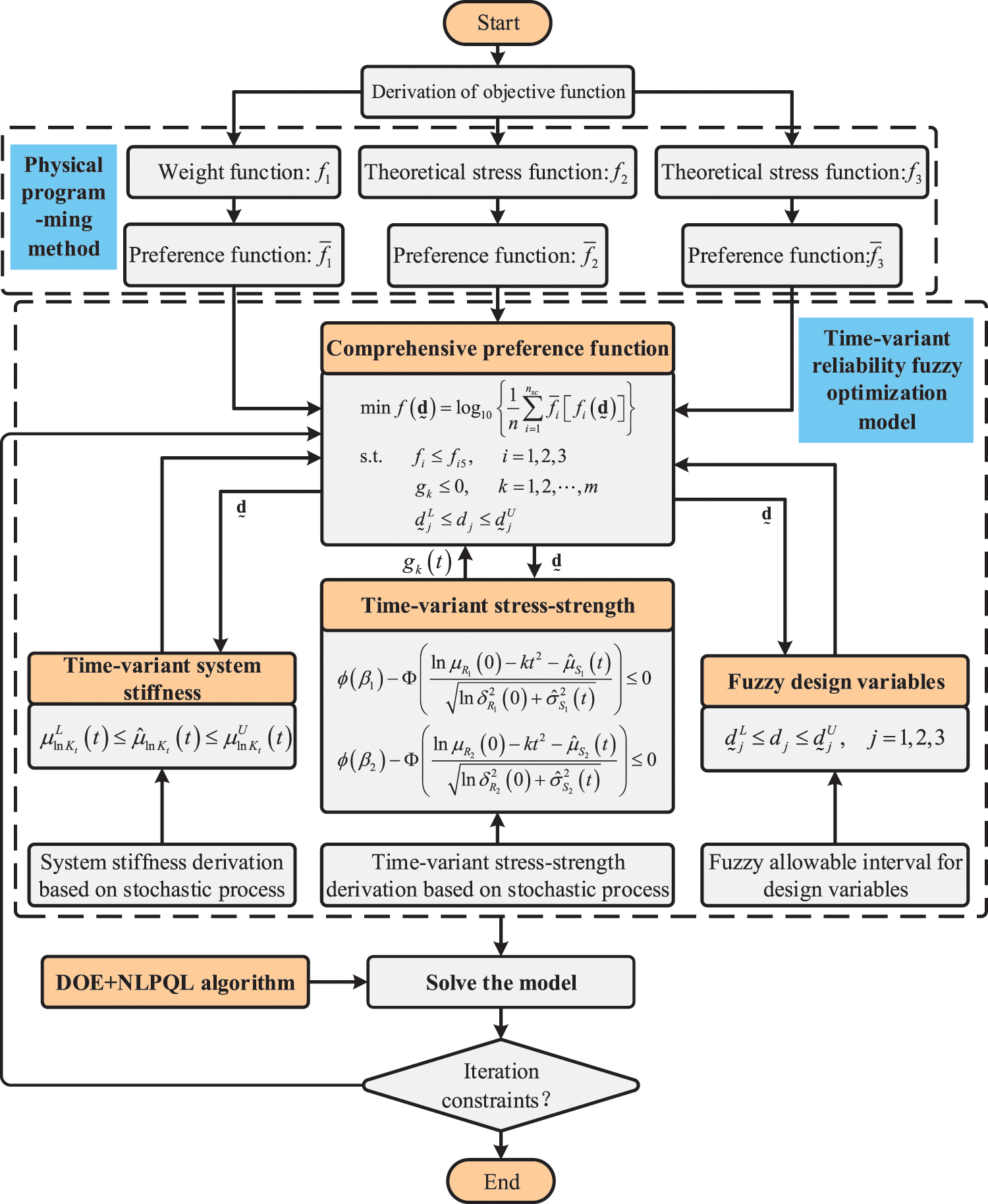
Figure 5: The framework of the proposed TRBMFDO method
5 Practical Engineering Examples
The detailed structure of the anti-roll torsion bar is shown in Fig. 6. The material of the anti-roll torsion bar is 52GrMoV4, whose tensile strength is 1450 MPa, yield limit is 1300 MPa, and allowable stress is 745 MPa.
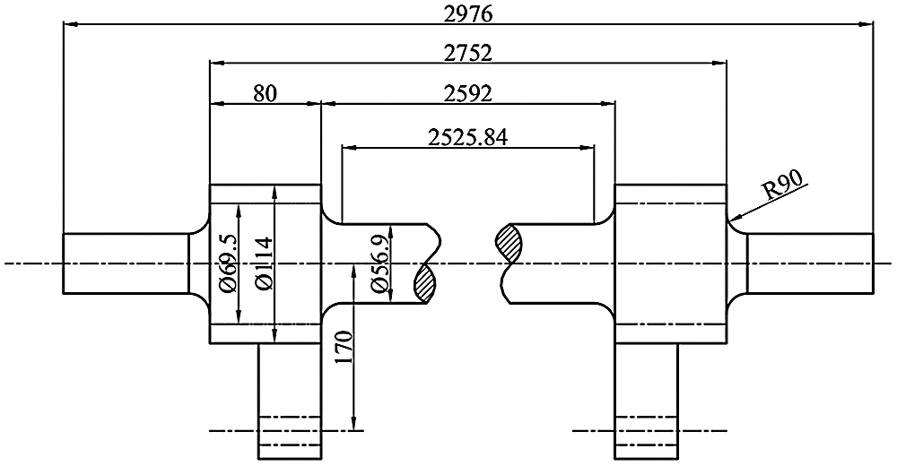
Figure 6: Structural diagram of the torsion bar
5.1 Time-Variant Stiffness of the Torsion Bar
The initial stiffness of the torsion bar in the working area, transition area, and connection area can be calculated, respectively
In order to obtain the distribution parameters of d(t), the experimental data about the torsional stiffness of the torsion bar are collected, shown in Fig. 7.
With the collected data in Fig. 7, the shift and volatility rate of the stiffness can be estimated as
When the drift and volatility rate are substituted into Eqs. (13)–(15), the time-variant stiffness of the torsion bar can be obtained at t = 9000.
Then the time-variant stiffness of the torsion bar is
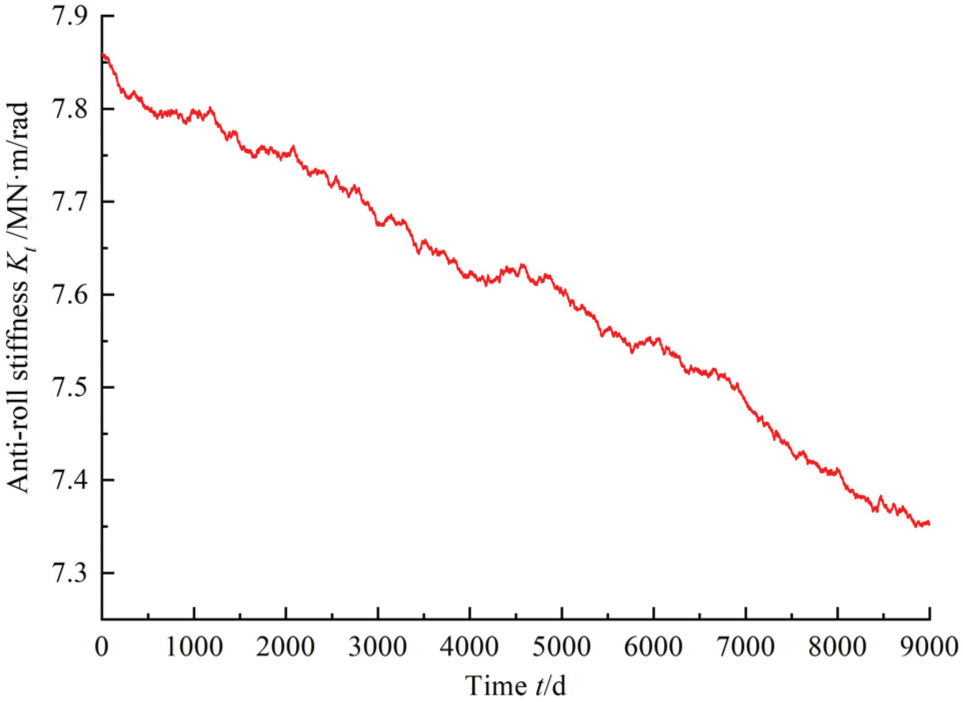
Figure 7: Historical observations of torsion bar stiffness
Considering the design requirements and stiffness change with time of the torsion bar, the constraint of stiffness is given as5.2 Time-Variant Strength of the Torsion Bar
According to the CRH3-350-PS-021 technical specification, the loadings of the torsion bar mainly include the static loading
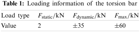
The value of the loading is usually determined by the vehicle's center of gravity deviation and the outside lateral force. The expressions of the loading normal condition and special condition are provided by
When designing the torsion bar, three conditions should be satisfied: (1) the maximum stress should be less than the fatigue limit of the material; (2) the maximum stress is not greater than the yield strength of the material; (3) the maximum shear stress is less than the allowed shear stress of the material under the special load case. The stresses of the torsion bar under the normal and special conditions are calculated based on Eq. (9):
where
The stresses of
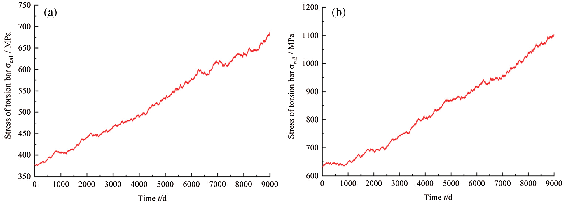
Figure 8: Historical observations of torsion bar stress (a) Torsion bar stress
With the collected data in Fig. 8, the shift and volatility rate of the stress can be estimated as
When the drift and volatility rate are substituted into Eq. (19), the time-variant stress of the torsion bar can be obtained at t = 9000.
5.3 Degradation of the Material Strength and Time-Variant Stress Constraints
Due to the existence of the failure modes of fatigue, wear and corrosion, the strength of the bar will degrade with time. The collected historical data of the allowable stress is provided in Fig. 9.
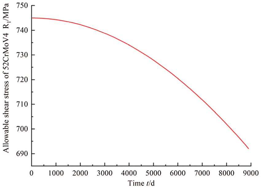
Figure 9: Historical observations of the material strength
When the data in Fig. 9 is considered as the inputs of Eqs. (20)–(22), the mean and standard deviation of allowable shear stress can be obtained.
The mean and standard deviation of the yield limit can be expressed by
The time-variant reliability constraints of the stresses are provided
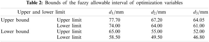
5.4 Fuzzy Allowable Interval of Design Variables
The diameters of the working area, transition area, and connection area for the anti-roll torsion bar of the EMU are usually uncertain, because the uncertainty is from the design, manufacturing and the working conditions. According to the design rule, the upper and lower bounds of expansion coefficients for diameter are
The optimal level cut set obtained by the fuzzy comprehensive evaluation is
5.5 Fuzzy Optimization Model of Time-Variant Reliability for the Anti-Roll Torsion Bar
In this example, the objective is to maximize the strength and stiffness, and meanwhile to minimize the mass of the anti-roll torsion bar under the satisfaction of the reliability and other performance constraints.
The mass can be calculated by
where
The stresses are given by
The preference function interval of optimization objectives can be obtained based on relevant standards and engineering experience, provided in Table 3.
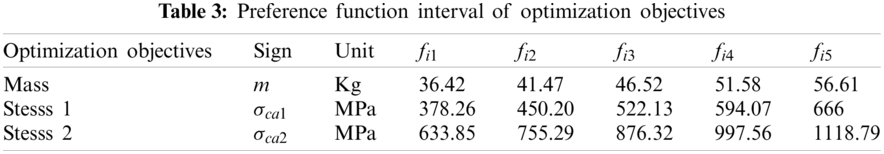
By using Eqs. (27)–(34), the preference function expression of each optimization objective can be obtained by piecewise function fitting.
The expression of preference function for the mass of the anti-roll torsion bar is
The expression of preference function for the stress
The expression of preference function for the stress
The fitting curve of preference functions for the mass, stress
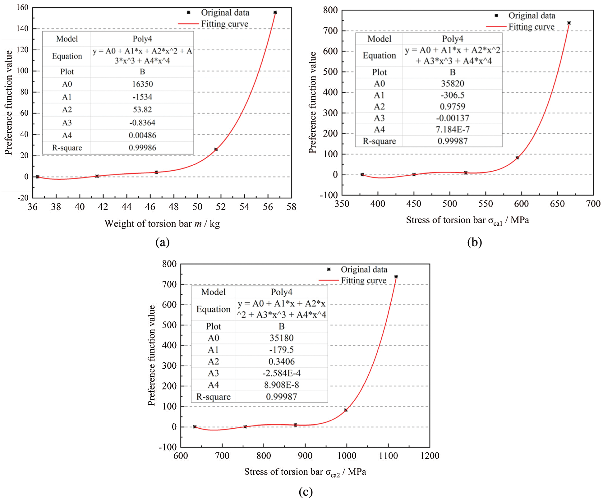
Figure 10: Fitting curve of preference function. (a) Preference function curve of the mass (b) Preference function curve of the stress
With the obtained preference functions of the objective functions and the related constraints, the TRBMFDO model is
5.6 Solving the TRBMFDO Problem
Since the complicated and coupled relationship exists in the TRBMFDO model, it is difficult to obtain the highly efficient and accurate results of the design by using general optimization strategies. In order to obtain the global optimal results effectively, a hybrid optimization strategy is implemented with integrating DOE sampling and numerical optimization. This hybrid optimization strategy can reduce the probability of trapping in the local optimal solution. The main task of the proposed strategy is that DOE method is employed to draw samples in the design region evenly and the parameter optimization module is to conduct design optimization for the optimal design results. The flowchart of the hybrid optimization strategy is provided in Fig. 11.
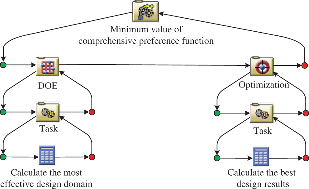
Figure 11: The hybrid optimization strategy
Three combinations based on the DOE including DOE+NLPQL, DOE+MIGA and DOE+ASA are used for the problem. The related results are provided in Table 4. From Table 4, we can see that the DOE+NLPQL strategy is better than the DOE+MIGA and DOE+ASA methods in the computational efficiency under the satisfaction of the computational accuracy. The DOE+MIGA and DOE+ASA optimization strategies require a total of more than 1000 function calls respectively, but the DOE+NLPQL optimization strategy requires only 17 function calls. The optimization results from the non-fuzzy method (the cut level set method) is lightly more conservative, which will reduce the objective of the lightweight design of the torsion bar. The reliability of the torsion bar increases 14% and 4.7%, respectively under the fuzzy optimization and non-fuzzy optimization methods. The mass of the torsion bar obtained by the fuzzy optimization method is 56.265 kg, a decrease of 0.14%; while the mass of the torsion bar obtained by the fuzzy optimization method is 56.265 kg, a decrease of 0.6%. The iterative processes of the fuzzy and non-fuzzy optimization with three different optimization strategies are given in Fig. 12.
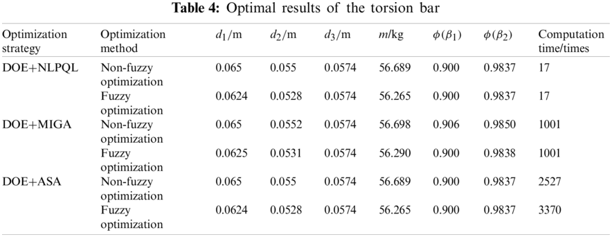
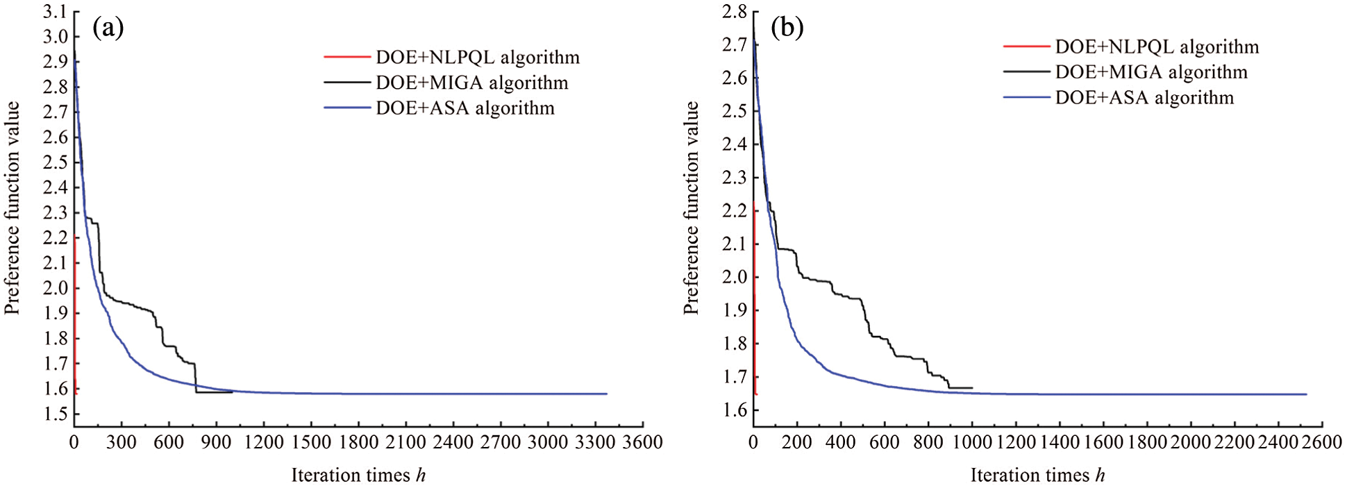
Figure 12: Iterative processes of the fuzzy and non-fuzzy optimization. (a) Iterative process of fuzzy optimization (b) Iterative process of non-fuzzy optimization
It can be seen from Fig. 12 that the preference function value based on the fuzzy optimization method is lower than that based on the non-fuzzy optimization method. It means that the optimal solution of the multi-objective function obtained by the fuzzy optimization method is better than that by non-fuzzy optimization method. It also shows that the number of iterations of the DOE+NLPQL optimization strategy is smaller than that of the other two optimization strategies. The better computational efficiency of the proposed method is further validated.
To further verify the differences between the three optimization strategies in the optimization process, the design space and the optimal solution set are shown in Fig. 13. The solution set of the physical programming and the solution set of the DOE+ASA optimization strategy are more evenly distributed in the whole design space, but more function calls are needed. The solution set of the DOE+MIGA optimization strategy is still evenly distributed in the whole design space, however the number of iterations reduces because the solution set is around the concentration. Nevertheless, the DOE+NLPQL optimization strategy can quickly capture the optimal domain to obtain the global optimal solution with a minimum set of solutions.
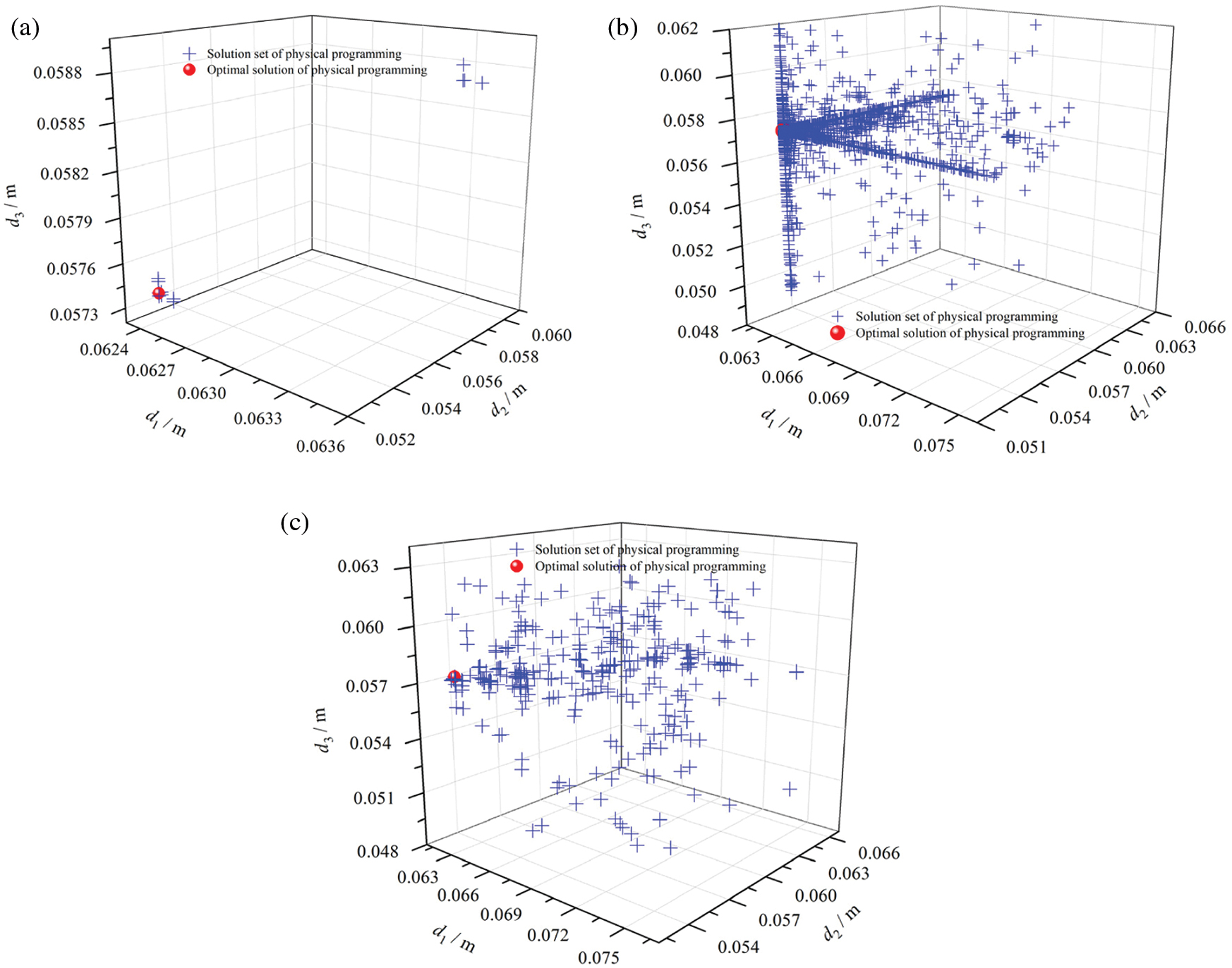
Figure 13: Optimal solutions of the physical programming with three optimization strategies. (a) The DOE+NLPQL optimization strategy (b) The DOE+MIGA optimization strategy (c) The DOE+ASA optimization strategy
In this paper, a TRBMFDO method for the anti-roll torsion bar of the EMU is proposed, which will be an effective tool to design the anti-roll torsion bar optimally under the satisfaction of the lifecycle reliability and safety. The time-variant reliability models of the torsion bar are first built related to the stiffness and strength considering the uncertainty and time-variant property. The physical programming method is then presented to handle the multi-objective design optimization to avoid the selection of the weight factors. The fuzzy allowable interval of design variables is then estimated based on the fuzzy theory. The comprehensive preference function is solved by the DOE+NLPQL hybrid optimization strategy. With the practical example, it is testified that the reliability of the anti-roll torsion bar increases by 14% during the lifecycle, and the weight of the torsion bar decrease by 0.6%. For the proposed DOE+NLPQL optimization strategy, only 17 function calls are needed for the global optimal solution, and therefore the computational efficiency increased by over 58.8 times compared with the DOE+ASA optimization strategy and the DOE+MIGA optimization strategy. In our future work, we will consider more time-variant failure modes including wear, corrosion and so on.
Funding Statement: This work was supported by Sichuan Science and Technology Program under the Contract No. 2020JDJQ0036.
Conflicts of Interest: The authors declare that they have no conflicts of interest to report regarding the present study.
1. Wang, Y., Zeng, S. K., Guo, J. B. (2013). Time-dependent reliability-based design optimization utilizing nonintrusive polynomial chaos. Journal of Applied Mathematics, 2013, 1–16. DOI 10.1155/2013/513261. [Google Scholar] [CrossRef]
2. Wang, Z. L., Cheng, X. W., Liu, J. (2017). Time-dependent concurrent reliability-based design optimization integrating experiment-based model validation. Structural and Multidisciplinary Optimization, 57(4), 1523–1531. DOI 10.1007/s00158-017-1823-0. [Google Scholar] [CrossRef]
3. Li, Y. H., Sheng, Z. Q., Zhi, P. P., Li, D. (2021). Multi-objective optimization design of anti-rolling torsion bar based on modified NSGA-iII algorithm. International Journal of Structural Integrity, 12(1), 17–30. DOI 10.1108/IJSI-03-2019-0018. [Google Scholar] [CrossRef]
4. Zhi, P. P., Xu, Y., Chen, B. Z. (2020). Time-dependent reliability analysis of the motor hanger for EMU based on stochastic process. International Journal of Structural Integrity, 11(3), 453–469. DOI 10.1108/IJSI-10-2018-0062. [Google Scholar] [CrossRef]
5. Li, L., Yuan, T. Y., Li, Y., Yang, W. Z., Kang, J. L. (2019). Multidisciplinary design optimization based on parameterized free-form deformation for single turbine. AIAA Journal, 12, 1–13. DOI 10.2514/1.J057819. [Google Scholar] [CrossRef]
6. Yu, X. Q., Du, X. P. (2006). Reliability-based multidisciplinary optimization for aircraft wing design. Structure and Infrastructure Engineering, 2, 277–289. DOI 10.1080/15732470600590333. [Google Scholar] [CrossRef]
7. Xu, H. W., Li, W., Wang, X., Hu, C., Zhang, S. C. (2016). Multidisciplinary reliability design optimization under time-variant uncertainties. Advances in Mechanical Engineering, 8(11), 1–11. DOI 10.1177/1687814016680177. [Google Scholar] [CrossRef]
8. Zhu, S. P., Keshtegar, B., Trung, N. T., Yaseen, Z. M., Bui, D. T. (2021). Reliability-based structural design optimization: Hybridized conjugate mean value approach. Engineering with Computers, 37, 381–394. DOI 10.1007/s00366-019-00829-7. [Google Scholar] [CrossRef]
9. Zhu, S. P., Keshtegar, B., Tian, K., Trung, N. T. (2021). Optimization of load-carrying hierarchical stiffened shells: Comparative survey and applications of six hybrid heuristic models. Archives of Computational Methods in Engineering, 28, 4153–4166. DOI 10.1007/s11831-021-09528-3. [Google Scholar] [CrossRef]
10. Zafar, T., Zhang, Y. W., Wang, Z. L. (2020). An efficient kriging based method for time-dependent reliability based robust design optimization via evolutionary algorithm. Computer Methods in Applied Mechanics and Engineering, 372, 113386. DOI 10.1016/j.cma.2020.113386. [Google Scholar] [CrossRef]
11. Zhao, D., Yu, S., Wang, Z. L., Wu, J. (2021). A box moments approach for the time-variant hybrid reliability assessment. Structural and Multidisciplinary Optimization, 64, 4045–4063. DOI 10.1007/s00158-021-03076-x. [Google Scholar] [CrossRef]
12. Rajabi-Bahaabadi, M., Shariat-Mohaymany, A., Babaei, M., Ahn, C. W. (2015). Multi-objective path finding in stochastic time-dependent road networks using non-dominated sorting genetic algorithm. Expert Systems with Applications, 42, 5056–5064. DOI 10.1016/j.eswa.2015.02.046. [Google Scholar] [CrossRef]
13. Mirjalili, S., Saremi, S., Mirjalili, S. M., Coelho, L. (2016). Multi-objective grey wolf optimizer: A novel algorithm for multi-criterion optimization. Expert Systems with Applications, 47, 106–119. DOI 10.1016/j.eswa.2015.10.039. [Google Scholar] [CrossRef]
14. Zhi, P. P., Li, Y. H., Chen, B. Z., Li, M., Liu, G. N. (2019). Fuzzy optimization design-based multi-level response surface of bogie frame. International Journal of Structural Integrity, 10(2), 134–148. DOI 10.1108/IJSI-10-2018-0062. [Google Scholar] [CrossRef]
15. Yu, S., Wang, Z. L., Wang, Z. H. (2019). Time-dependent reliability-based robust design optimization using evolutionary algorithm. ASCE-ASME Journal of Risk and Uncertainty in Engineering Systems, Part B: Mechanical Engineering, 5, 0200911. DOI 10.1115/1.4042921. [Google Scholar] [CrossRef]
16. Zhang, X. L., Huang, H. Z., Yang, Y. J., Meng, D. B., Peng, W. (2016). Dynamic reliability based design optimization of the lifting gear transmission system for mining excavator. Annual Reliability and Maintainability Symposium, pp. 1–6. Tucson, AZ, USA. DOI 10.1109/RAMS.2016.7448043. [Google Scholar] [CrossRef]
17. Dong, Y., Frangopol, D. M., Saydam, D. (2014). Pre-earthquake multi-objective probabilistic retrofit optimization of bridge networks based on sustainability. Journal of Bridge Engineering, 19(6), 04014018-1–04014018-10. DOI 10.1061/(asce)be.1943-5592.0000586. [Google Scholar] [CrossRef]
18. Okasha, N. M., Frangopol, D. M. (2010). Time-variant redundancy of structural systems. Structure and Infrastructure Engineering, 6(1), 279–301. DOI 10.1080/15732470802664514. [Google Scholar] [CrossRef]
19. Wang, P. F., Wang, Z. Q., Almaktoom, A. T. (2013). Dynamic reliability-based robust design optimization with time-variant probabilistic constraints. Engineering Optimization, 46(6), 784–809. DOI 10.1080/0305215X.2013.795561. [Google Scholar] [CrossRef]
20. Angelis, M. D., Patelli, E., Beer, M. (2017). Forced monte carlo simulation strategy for the design of maintenance plans with multiple inspections. ASCE-ASME Journal of Risk and Uncertainty in Engineering Systems, Part A: Civil Engineering, 3(2), D4016001-1–D4016001-9. DOI 10.1061/AJRUA6.0000868. [Google Scholar] [CrossRef]
21. Duan, L. J., Yuan, W. H. (2019). Project method of stiffness and strength analysis about anti-rolling torsion bar system of rail vehicle bogie. Modern Manufacturing Engineering, 7, 49–55. DOI 10.16731/j.cnki.1671-3133.2019.07.008. [Google Scholar] [CrossRef]
22. Lu, C., Dai, X. C., Dong, B., Ma, R. C., Wang, C. (2019). Characteristics analysis and experimental research on anti-rolling bar device. Machine Design and Manufacturing Engineering, 48(2), 107–110. DOI 10.3969/j.issn.2095-509X.2019.02.026. [Google Scholar] [CrossRef]
23. Wang, W. J., Zhang, Z. P., Li, G. Q., Song, C. Y. (2019). Study on load characteristics of anti-rolling torsion bar of high speed train. Journal of Southwest Jiaotong University, 54(6), 1277–1283. DOI 10.3969/j.issn.0258-2724.20180060. [Google Scholar] [CrossRef]
24. Dong, S. D., Li, Y. H. (2015). Multi-response robust optimization of anti-rolling torsion bar based on the stochastic model. Journal of Railway Science and Engineering, 12(4), 900–904. DOI 10.19713/j.cnki.43-1423/u.2015.04.030. [Google Scholar] [CrossRef]
25. Sumit, B., Tushar, M., Sonali, T., Baskar, P. (2016). Analysis of effect of polyurethane bushing on stress distribution of anti-roll bar. International Journal of Engineering Research and General Science, 4(3), 90–96. DOI 10.1016/j.ergs.2016.04.015. [Google Scholar] [CrossRef]
26. Meng, Z., Guo, L. B., Hao, P., Liu, Z. T. (2021). On the use of probabilistic and non-probabilistic super parametric hybrid models for time-variant reliability analysis. Computer Methods in Applied Mechanics and Engineering, 386, 114113. DOI 10.1016/j.cma.2021.114113. [Google Scholar] [CrossRef]
27. Meng, Z., Zhao, J. Y., Jiang, C. (2021). An efficient semi-analytical extreme value method for time-variant reliability analysis. Structural and Multidisciplinary Optimization, 64(3), 1469–1480. DOI 10.1007/s00158-021-02934-y. [Google Scholar] [CrossRef]
28. Messac, A., Ismail-Yahaya, A. (2002). Multiobjective robust design using physical programming. Structural and Multidisciplinary Optimization, 2, 357–371. DOI 10.1007/s00158-002-0196-0. [Google Scholar] [CrossRef]
29. Zhi, P. P., Li, Y. H., Chen, B. Z., Bai, X. N., Sheng, Z. Q. (2020). Fuzzy design optimization-based fatigue reliability analysis of welding robots. IEEE Access, 8, 64906–64917. DOI 10.1109/access.2020.2984694. [Google Scholar] [CrossRef]
30. Jiao, J., Ren, H., Sun, S. (2016). Assessment of surface ship environment adaptability in seaways: A fuzzy comprehensive evaluation method. International Journal of Naval Architecture & Ocean Engineering, 8(4), 344–359. DOI 10.1016/j.ijnaoe.2016.05.002. [Google Scholar] [CrossRef]
 | This work is licensed under a Creative Commons Attribution 4.0 International License, which permits unrestricted use, distribution, and reproduction in any medium, provided the original work is properly cited. |