| Computer Modeling in Engineering & Sciences |
DOI: 10.32604/cmes.2022.020572
REVIEW
Recent Progress on Aeroelasticity of High-Performance Morphing UAVs
Institute of High Speed Aerodynamics, China Aerodynamics Research and Development Center, Mianyang, 621000, China
*Corresponding Author: Kaichun Zeng. Email: zengkaichun@cardc.cc
Received: 01 December 2021; Accepted: 07 February 2022
Abstract: The high-performance morphing aircraft has become a research focus all over the world. The morphing aircraft, unlike regular unmanned aerial vehicles (UAVs), has more complicated aerodynamic characteristics, making itmore difficultto conduct its design, model analysis, and experimentation. This paper reviews the recent process and the current status of aeroelastic issues, numerical simulations, and wind tunnel test of morphing aircrafts. The evaluation of aerodynamic characteristics, mechanism, and relevant unsteady dynamic aerodynamic modeling throughout the morphing process are the primary technological bottlenecks formorphing aircrafts. The unstable aerodynamic forces have a significant impact on the aircraft handling characteristics, control law design, and flight safety. In the past, the structural analysis of morphing aircrafts, flight dynamics modeling, computational mesh morphing technology, and aerodynamic calculation were performed in promoting the development of next generation UAVs, with nonlinear dynamic challenges includingtransonic aeroelastic problems and high angle of attack aeroelastic problems. At present, many facets of these difficulties, together with the accompanying numerical simulation studies, remain under-explored. In addition, wind tunnel experiments face significant challenges in the dynamic morphing process. Finally, dynamic unsteady aerodynamic characteristics in the continuous morphing process still need to be verified by more related experiments.
Keywords: Morphing aircraft; aeroelasticity; numerical simulation; wind tunnel test
1.1 Morphing Aircraft Technology
Traditional fixed-wing aircrafts were designed first for the primary flight environment and tasks (such as cruise, reconnaissance, and combat, etc.), while also accounting for critical flight processes like take-off and landing, and then compromised optimized design [1–3]. As a result, aircrafts that perform different functions and travel at different speeds would have extremely distinct designs, such as subsonic long-range drones represented by the Global Hawk, supersonic fighters represented by the F-16, and hypersonic vehicles represented by the HTV-2 and X-51A. Flying creatures provide excellent illumination. In cruising, hovering, diving, and attacking, they will adopt a proper shape to provide the best aerodynamic force and flight performance. In view of this, scientists and engineers recommended designing a new concept aircraft called the morphing aircraft, which can accomplish performance optimization at all phases by changing the layout shape while completing different missions under varied flight conditions [4–6].
At present, research on morphing aircrafts is focused on the following topics: (1) what type of morphing the aircraft needs to generate; (2) how to realize morphing; (3) the safety during dynamic morphing; (4) how to control; (5) the cost. Aerodynamics, flight control, materials, structure, drive, morphing control, and other basic ideas have been explored [7,8]. The term “aircraft morphing” refers to a wide range of spatial scale and time scale (local, dispersed, and overall). It is divided into three categories based on the morphing scale and realized function: (1) local morphing (small morphing); (2) distributed morphing (medium-scale morphing); (3) integral morphing (large-scale morphing). Meanwhile, it can also be divided into two types based on the realization method: (1) mechanical morphing; (2) smart materialsand structures based morphing [9].
The research on morphing aircrafts began in 1903 and developed from the Wright brothers’ initial aircraft, which depended on flexible deformable wings, to the variable-sweep wing technology exemplified by the F-14 in the 1960s and 1970s. In recent years, the continuous variable trailing edge camber technology used on the Gulfstream III aircraft has been a hot topic in the aerospace industry. It may triggertechnological advancements in aircrafts and have a disruptive influence. It has attracted wide attention all over the world [10]. From the perspective of basic scientific problems and bottleneck technologies, the main problems include two aspects: (1) Aerodynamics, flight mechanics, and flight control of morphing aircrafts; (2) morphing structure, drive, and morphing control [6,11].
Since the 1980s, a lot of manpower and financial resources have been invested to develop morphing technologies to improve the overall performance of aircrafts [12]. Some research projects onthe aircraft intelligent morphing control technology were carried out, such as the Mission-Adaptive Wing (MAW), the Active Flexible Wing (AFW), the Smart Wing Project (SWP), the Active Compliant Trailing Edge flaps (ACTE), and the Variable Continuously Camber Trailing-Edge Flaps (VCCTEF) [13–15]. Later, some mature wing morphing technologies in Europe and the United States have passed wind tunnel tests and flight tests, and are getting increasingly close to practical engineering applications. However, the research work on morphing aircrafts still needs new conceptual design and is still in the exploratory research stage [16]. Nevertheless, some scholars have researched the wing morphing technology. For example, Huang [17] explored the application of a new type of zero Poisson’s ratio honeycomb structure in variable camber wings. Li [18] designed a multi-joint adaptive wing trailing edge based on memory alloy differential drive. Liu et al. [19] proposed a design scheme for the front and rear edges of the variable camber wing based on a distributed flexible structure, a closed-chain skeletal mechanism, and a rigid-flexible coupling mechanism. Although specific technologies have been studied in the existing literature, there isno systematic and in-depth review on key aerodynamics and related technical issues. It is highly complex and difficult due to the lack of strong support from basic technologies such as smart materials, flexible skins, and memory alloys, as well as variant technologies involving aerodynamics, structure, control, aeroelasticity, and interdisciplinarity [20,21].
As one filiation of mechanics, aeroelasticity mainly focuses on mechanical characteristics, the law of gas flow, and concomitant physical and chemical changes of aircrafts flying in the air. Along with the development of aircraft industry and jet propulsion technology, it gradually becomes a subject. Usually, the main research contents of aeroelasticity are velocity, temperature, pressure and density of gas, lift force and drag force of aircrafts and change laws, etc. when aircrafts are flying in various conditions. Based on different flight environments, morphing UAVs can autonomously change their aerodynamic configuration aiming to efficiently finish corresponding flight mission. Therefore, aeroelasticity is the key issue formorphing UAVs. It mainly involves dynamic problems, aeroelastic numerical simulation, aeroelastic wind tunnel test, etc., which will be reviewed in the following texts.
1.2 Numerical Simulation of Aeroelasticity
In the aerospace field, the process of aeroelastic analysis methods is similar to that of many other disciplines. Before the application of electronic computers, it mainly focuses on experimental and analytical methods [22,23]. However, there are many difficulties in aeroelastic problems, especially in the high-speed wind tunnel aeroelastic experiment. Therefore, the calculation method of aeroelasticity has become an important research and development direction [24,25].
The aeroelastic problems of early aircrafts mainly lie in the wings, while the early wings were straight with relatively large chords. Therefore, the aeroelastic analysis methods can only be developed around the aerodynamic characteristics of two-dimensional (2D) wings [13]. After the 1950s, with the development of high-speed aircrafts, the aeroelastic analysis method of high-speed wings based on piston theory was developed. However, the calculation method that can solve the aeroelastic problem of actual aircrafts depends on the development of computer technology [26]. In the 1970s, the unsteady lift surface method based on the potential streamline theory was widely used and developed rapidly. It is still the main method in engineering nowadays and has been embedded in the famous analysis software NASTRAN. In the late 1980s, as the computer processing speed increased, aeroelastic analysis methods based on the full-speed potential equation and Euler equations were developed. In particular, Euler equations helped solve the long-term trouble (transonic aeroelastic problem), but they are under the assumption of inviscid flow, thus failing to consider the significant influence of viscous effects. In recent years, aeroelastic analysis methods based on the N-S equation have been developed. However, these methods entail huge amount of numerical calculation of the unsteady flow. The computer technology is still incapable of realizing the aeroelastic numerical simulation of the viscous flow problem [27]. The development direction of aeroelasticity is thus clear. With the further increase in computer speed, the development of parallel computer speed, and the advancement of numerical calculation methods, numerical simulation to solve complex aeroelastic problems will gradually become a reality [28,29].
1.3 Aeroelastic Wind Tunnel Test
Aeroelastic wind tunnel test has the advantages of high reliability (compared to numerical calculation) and low cost (compared to flight test). The scaled-down similar model is tested in a wind tunnel, which can simulate the aeroelastic characteristics of the aircraft more accurately. Therefore, the wind tunnel test has always been one of the important means to analyze and evaluate the aeroelastic characteristics of aircrafts. In the design stage, the aeroelastic characteristics of the aircraft must be analyzed through wind tunnel tests to verify whether its strength designed and performance indicators meet the requirements, and corresponding optimization and improvement should be made. The wind tunnel flutter test is usually conducted before the flight test, so that its results can be used to provide a basis for and reduce the risk of the flight test. In addition, the aeroelastic wind tunnel test also provides the technical support for the verification of advanced aerodynamics, structural coupling design, and analysis methods. The transonic dynamics tunnel (TDT) of the Langley Center of NASA was completed in the early 1960s. By 2016, more than 600 wind tunnel tests had been carried out. Most of them are aeroelastic tests, including fixed-wing aircrafts, rotary-wing aircrafts, launch vehicles, and other configurations, which have greatly facilitated the aeroelastic design and analysis of the research models, the engineering application of new layouts and new technologies, and numerical calculation methods. Therefore, the aeroelastic wind tunnel test technology is a solid foundation for the research and development of aerospace vehicles [30,31].
This paper takes high-performance morphing aircrafts as the research object, aiming at reviewing the aeroelastic problems in the morphing process, comprehensively explaining the key problems in morphing aircrafts and the research progress, and respectively analyzing the aeroelastic numerical simulation methods. Finally, aeroelastic wind tunnel test technologies are elaborated.
2 Aeroelastic Problems of High-Performance UAVs
2.1 Development History of Aeroelasticity
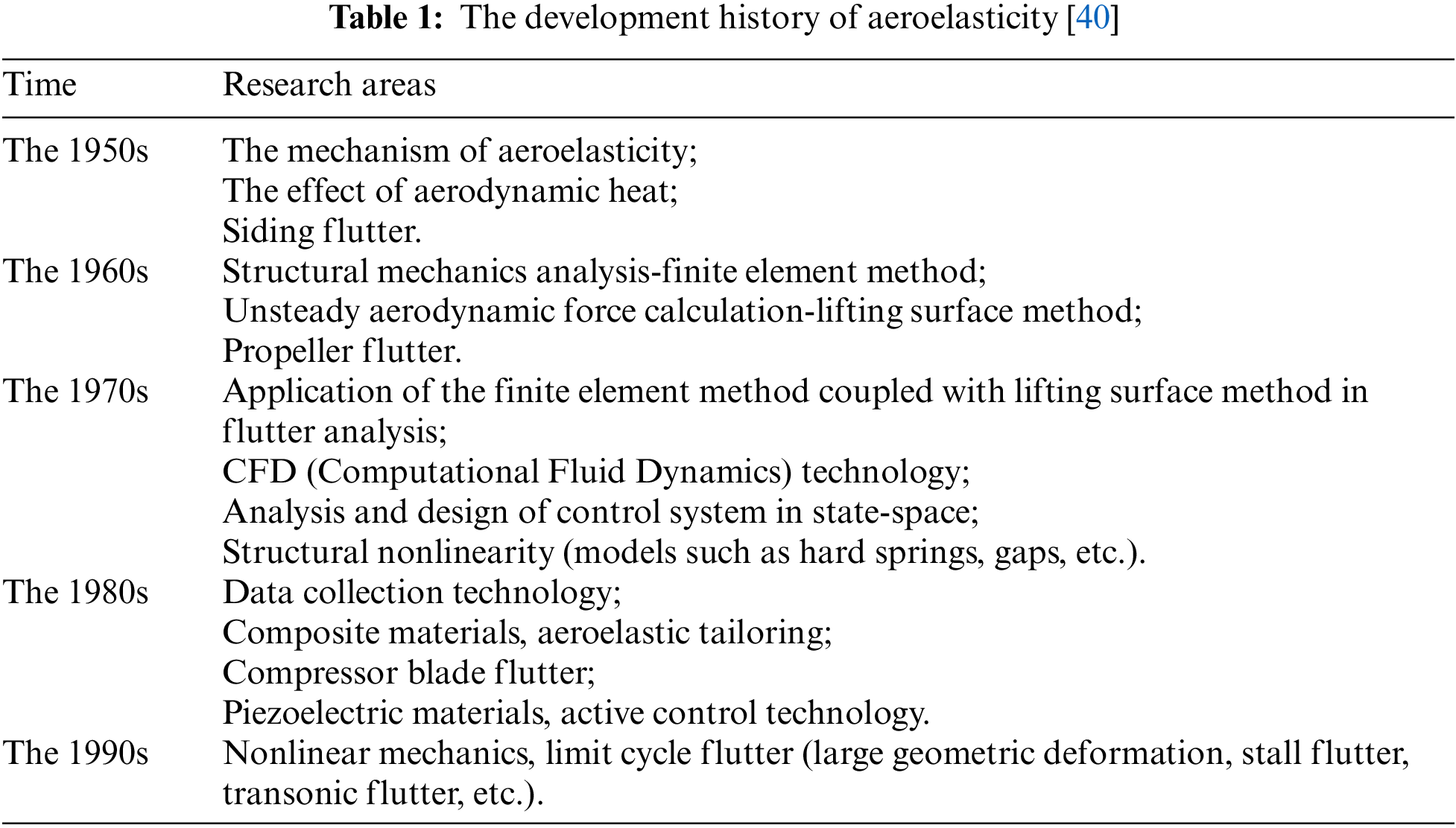
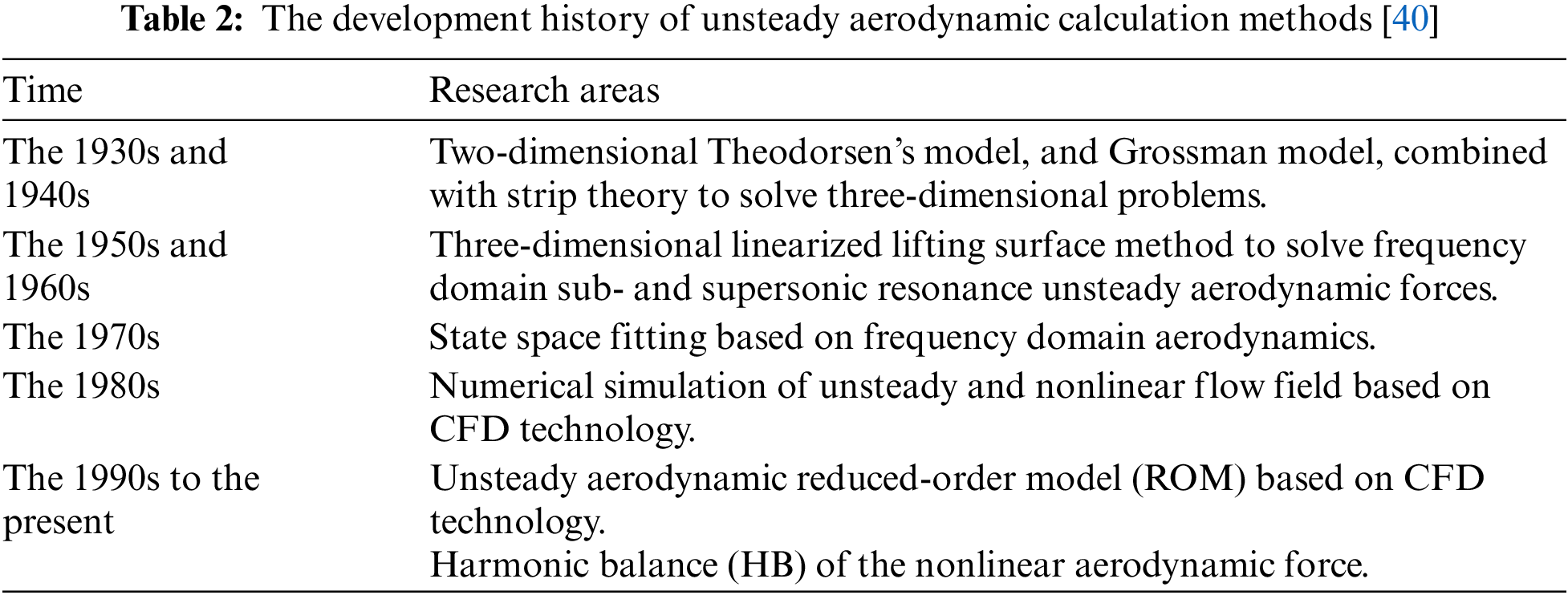
The aeroelastic problems of aerospace vehicles have accompanied the development of aircrafts. As early as 1903, Langley’s monoplane suffered a broken wing during its first powered flight. After the Wright brothers succeeded in achieving a powered flight that was heavier than air, the development of aircrafts accelerated rapidly, and the aeroelastic problem became increasingly prominent. In the 1920s, the research on wing flutter analysis had achieved rapid progress [32]. Representative research included Theodorsen’s unsteady aerodynamic analysis method of the simple harmonic vibration airfoil, and studies on the theory of the wing flutter and other content [33]. After entering the 1950s, due to the emergence of high-speed aircrafts, the problem of thermo-aeroelasticity attracted the attention of researchers. Because the hypersonic aircraft was mainly focused on spacecraft at that time, the problem of thermo-aeroelasticity was not systematically solved [34,35]. After the 1980s, the aircrafts focused on the transonic flight, and the study of nonlinear aeroelastic problems related to transonic speeds obtained systematic and in-depth investigations [36,37]. In recent years, with the development of micro-aircrafts, the aeroelasticity of flexible deformable wings has also attracted wide scholarly attention [38,39]. In short, the research of aerospace aeroelasticity is closely related to the development of aircrafts and mechanical analysis methods. Tables 1 and 2 respectively summarize the development history of aeroelasticity and unsteady aerodynamic calculation methods.
2.2 Classification of Aeroelastic Problems
(1) Wing torsional divergence
Fig. 1 shows the schematic diagram of a two-dimensional wing. The initial angle (initial angle of attack) is
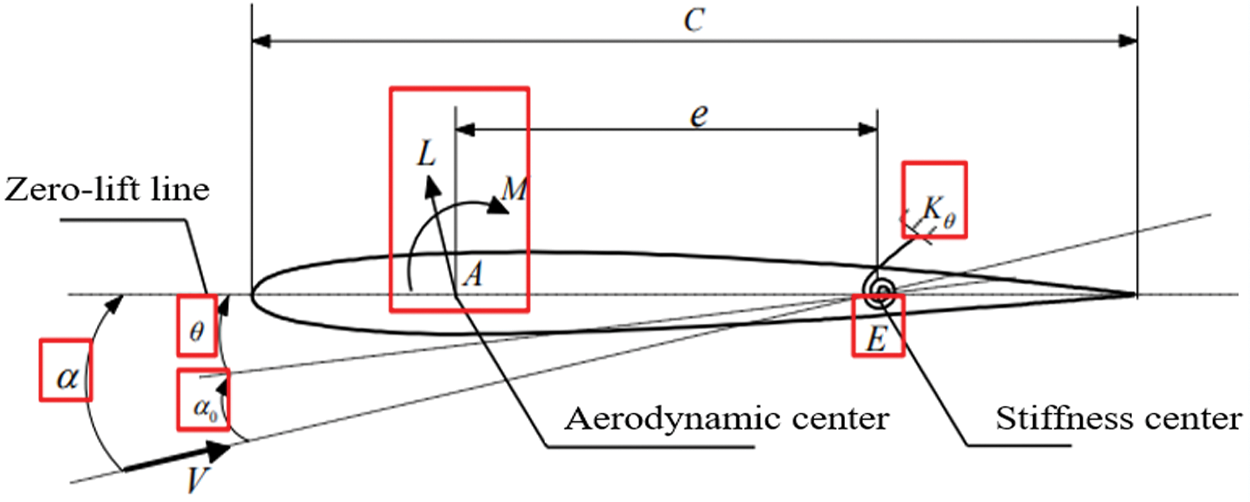
Figure 1: Two-dimensional wing redrawn based on reference [29]
(2) Load redistribution
When the dynamic pressure is less than the torsional divergent dynamic pressure, the torsion angle and the aerodynamic lift are definite finite values and change with the change of dynamic pressure. This change will inevitably affect the flight performance of the aircraft, which is the redistribution of aerodynamic load. In the design of aircrafts, the possibility of the system static divergence instability should be avoided, but the redistribution of the load is inevitable. Engineers should design the initial airfoil that happens to be the cruise profile after loading.
(3) Reversal of the control surface
Fig. 2 shows a two-dimensional wing with an aileron. The initial angle of attack is 0. Manipulate the aileron to make it deflect downward at an angle
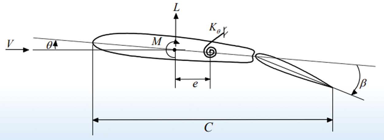
Figure 2: The statics model of a binary wing with control surfaces [40]
When the speed is lower than the reaction critical speed, the reduction in the aileron control efficiency can be expressed by the control efficiency. Assuming that the wing is rigidly supported, it is obvious that the lift increment generated after controlling the aileron deflection angle is only related to the angle. The lift coefficient is shown as Eq. (1):
The aileron control efficiency of a two-dimensional wing is defined as the ratio of the lift coefficient of the elastically supported wing to the lift coefficient of the rigidly supported wing, as Eq. (2):
where the aileron control efficiency
(a) If
(b) If
(c) If
(1) Flutter
Flutter is a self-excited vibration with the nonattenuation amplitude due to the coupling of the aerodynamic force, the elastic force, and the inertial force when the aircraft exceeds a certain critical flight speed. Its essence is the dynamic instability of the aeroelastic system, and it often causes catastrophic damage [41–43]. For example, in 1997, the first stealth fighter bomber F-117 crashed due to the flutter of the control surface. Currently, the wide application of lightweight flexible composites makes the structure of a new generation of aircrafts increasingly flexible. The structural plasticity of both the airframe and the aerodynamic rudder used for attitude control is greatly increased, which provides a sufficient internal cause for the occurrence of flutter. With the emergence of new technologies, the difficulty and breadth of aircraft flutter problems are indirectly exacerbated. Aircraft structure design and flutter suppression design will face great challenges.
(2) Gust response
Because the atmosphere is unstable, the aircraft cannot fly in the static air, and it is often affected by atmospheric turbulence. At this time, the aircraft may bear an excessively high load and cause a flight accident or seriously affect the flight performance and the safety and the comfort of the crew. There is no shortage of flight accidents caused by wind gusts in the history of aviation. Therefore, the aircraft strength and rigidity specifications stipulate that gust load calculations must be performed to verify whether the aircraft has sufficient strength and rigidity to ensure the safety and meet the operational requirements. At present, the flight experiment technology faces the challenges of great difficulty, long period, and extremely high cost. Various engineering algorithms and numerical analysis methods are mainly used to study the gust response. Gusts can be divided into vertical gusts and horizontal gusts. The disturbance motion caused by the vertical gust of the aircraft is limited to the longitudinal motion, and the disturbance motion caused by the horizontal gust of the aircraft is limited to the lateral movement, which can greatly simplify the gust response analysis.
(3) Buffeting
Wing buffeting is the dynamic response generated by the random aerodynamic excitation acting on the wing surface induced by the separation of airflow on the wing surface. The buffeting excitation comes from the generation of unsteady separated flows on the wings. It mainly includes the buffeting excitation at low speed and high angle of attack and the transonic shock wave buffeting excitation. There are three types of tail wing buffeting. The first type is the buffeting caused by the tail wing in the high-energy turbulence. Such buffeting can be caused when the tail is in the wake flow of the upstream fuselage, wing, or in the edge vortex rupture flow of the edge wing layout. The second type is the buffeting caused by the tail itself, which is similar to the buffeting of the wing at high angles of attack. At high angles of attack or sideslip, the airflow separation on the tail surface or the pressure pulsation caused by the shock-boundary layer interference when the flying Mach number is large can cause this kind of buffeting. The third type of buffeting belongs to coupled buffeting. When the frequency of other parts of the aircraft is close to the natural frequency of the tail wing, it is possible to cause the tail wing buffeting through structural coupling. The first type is the most important form of buffeting, which has the largest impact on the tail structure.
(4) Servo flutter
For the fly-by-wire aircrafts, the introduction of fly-by-wire flight control systems will cause a new flutter problem, namely servo flutter. The reason is that the modern aircrafts generally broaden the frequency band of the flight control system, especially for the aircrafts with active control functions. The frequency band of the controller often covers the frequency band of the low-order structural modal distribution, which will cause the high-frequency vibration response to be included in the sensor. Among the signals, it cannot be effectively attenuated when passing through the control loop, and even forms positive feedback, and then through the control surface and other actuating mechanisms to further excite structural vibration, thereby forming structural damage similar to flutter.
Since the actual aircraft is an elastic body, the sensor not only receives signals from the flight status but also receives vibration signals from wings and fuselage. These signals refed back to the rudder surface through the controller to form the high-frequency vibration of the rudder surface. This high-frequency vibration mode will be coupled with the original structural vibration mode, which may reduce the stability of the original aeroelastic system, resulting in servo flutter.
2.3 Bottlenecks in the Research of Aerodynamic Characteristics of Morphing Aircrafts
At this stage, there are three main types of flight dynamics models for morphing aircrafts: (1) the use of linearized small disturbance hypothetical flight dynamic model combined with the partial freezing method of the quasi-steady aerodynamic model; (2) the use of linearized small disturbance flight dynamic model for small-scale rapid morphing; (3) the flight dynamic model for large-scale slow morphing. The perturbed flight dynamic model is combined with the unsteady aerodynamics correction, which is suitable for large-scale and slow-speed morphing, considering the time change rate of inertia and the flight mechanics model of quasi-steady aerodynamics. For the case of the large morphing scale and the high speed, there is little related research. It is thus necessary to adopt a flight dynamic model that considers the time change rate of inertia combined with unsteady aerodynamic forces. The difficulty lies in the modeling of unsteady aerodynamic forces during the morphing process [44–46]. The ultimate goal of the research on aerodynamic and flight mechanics characteristics during the morphing process is to achieve reasonable and effective flight control during the morphing process and ensure the safety of the flight. On the basis of the effective control of the flight mode, it is necessary to ensure the safe and effective control during the dynamic conversion process. At present, this part of the research work is still in the exploratory stage for modern morphing aircrafts and especially for the flight control during the morphing process [47,48].
To achieve effective control during the morphing process, the first prerequisite is to accurately predict and deeply understand the unsteady dynamic aerodynamic characteristics of the aircraft during the morphing process, and to obtain an accurate and effective aerodynamic model [49]. This is very important for morphing aircrafts that exhibit strong unsteady nonlinear interference aerodynamic characteristics during complex morphing processes. However, this is also a great challenge for the current aerodynamic prediction technology [50]. Although many research institutions and universities have carried out wind tunnel experiments, numerical simulations, and theoretical analyses on the aerodynamic characteristics of morphing aircrafts, there is still a long way to go before achieving a mature technology state [51,52].
3 Current Status of Aeroelastic Numerical Simulation of High-Performance UAVs
In the morphing process, the unsteady dynamic aerodynamic features lack acknowledged analysis and support from relevant aerodynamic basic theories [53,54]. In terms of numerical simulation methodologies, the modern numerical simulation technology is capable of simulating the moving boundary’s unstable dynamic aerodynamic properties [55,56]. However, there is no effective theory or verification and confirmation of wind tunnel experimental results, and their rationality and correctness lack solid support [57].
3.1 Morphing Structure Analysis
The foundation of aeroelastic numerical simulation is morphing structural analysis [58,59]. There are two approaches for structural analysis: the analytical homogenization and the finite element method. The homogenization method [60] is based on partial differential equations with fast-changing factors. Its essence is to indefinitely magnify a specific spot in a heterogeneous material, revealing a periodic unit cell stacking structure at a meso-scale (the hypothesis of periodic structure is also the premise of the homogenization theory). The finite element method [61], often called finite element analysis (FEA) in practical applications, is a numerical method for solving partial differential equations. It is a high-efficiency and commonly used calculation method. It discretizes the continuum into a collection of several finite-size unit bodies to solve the continuum mechanics problem [62–64].
In order to obtain better performance of the deformed skin based on 2D thin beam elements, Ermakova et al. [65] proposed the shape optimization of corrugations (as shown in Fig. 3). Considering that the ratio of the Young’s modulus of the elastomer coating to the Young’s modulus of the composite corrugated core is small, the elastomer coating is ignored in the contact area. In Abaqus 6.12, S4R elements are used for finite element analysis, and the homogenization method [60] is used to evaluate the accuracy of the corrugated plate buckling mode, as shown in Fig. 4. Based on Castigliano’s second theorem, Dayyani et al. [66] proposed two analytical solutions for calculating the equivalent tensile and bending properties of the coated corrugated skin (as shown in Fig. 5). Since the elastomer coating and the composite corrugated core are well bonded together and the two have the same displacement, the strain energy term of the contact between the elastomer and the glass fiber can be ignored.
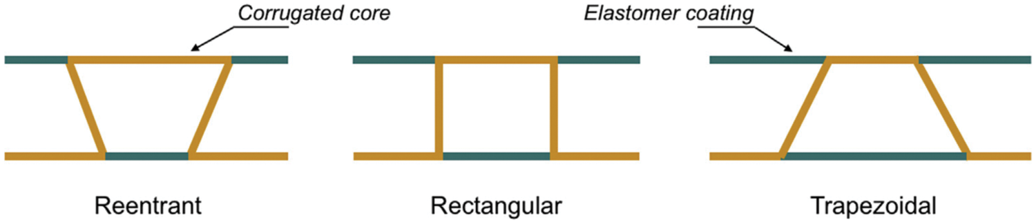
Figure 3: Three typical shapes of corrugation [65]
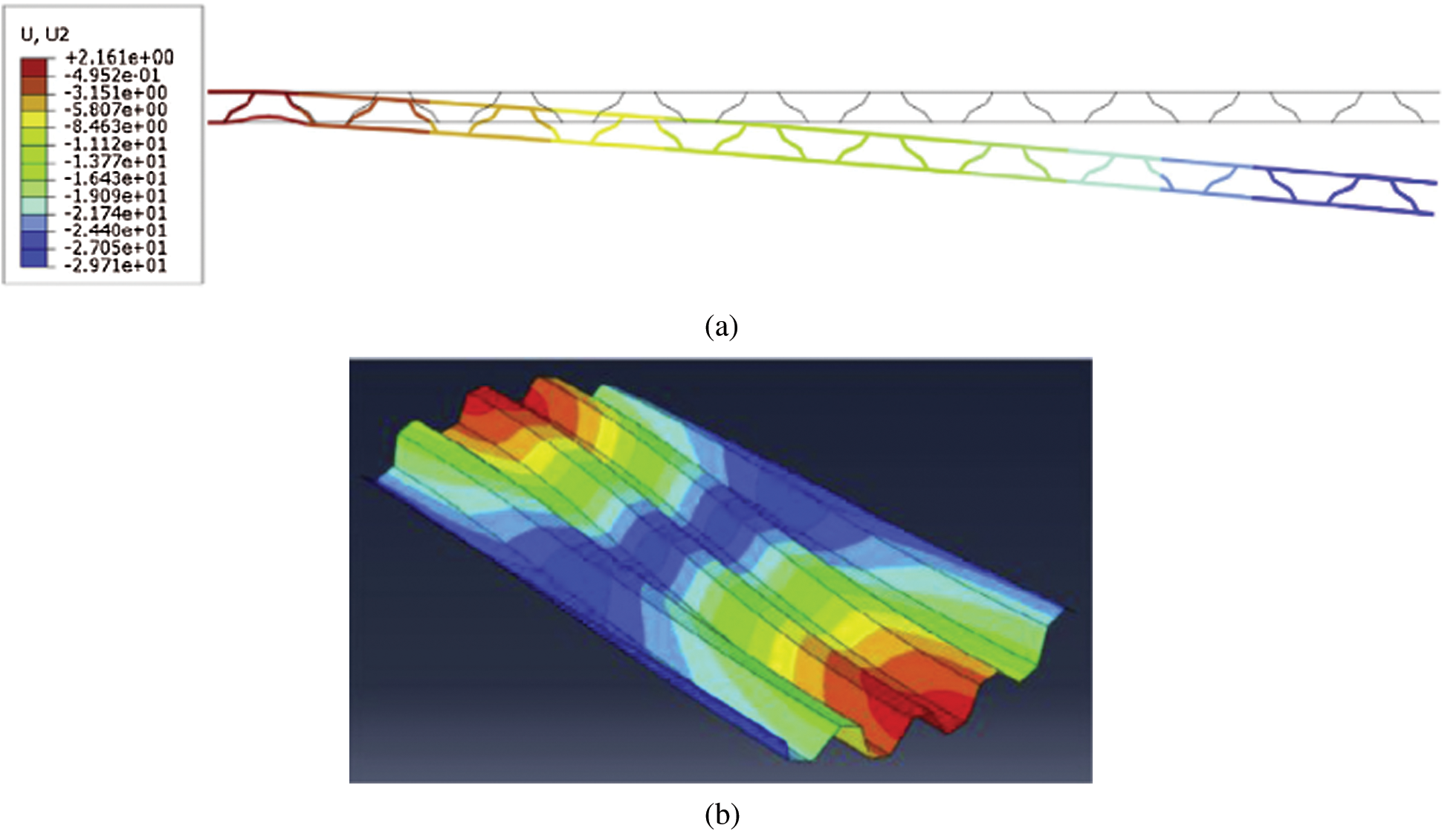
Figure 4: Homogenization method to evaluate the buckling mode of corrugated plate [60]: (a) bending of coated corrugated skin based on thin beam elements; (b) out-of-plane global buckling on S4R elements
Figure 5: The coated composite corrugated core [66]
Dayyani et al. [67] derived a general-purpose super unit for a corrugated core unit with elastic coating that can be applied to morphing aircraft structures. Through the direct stiffness method and Castigliano’s second theorem, together with appropriate boundary conditions, the stiffness matrix of an arbitrary corrugation curve (as shown in Fig. 6) is obtained. The matrix ignores the strain energy term of the elastic body in contact with the composite material and can be applied to small morphing of a 2D thin bending beam with the variable curvature. For beams with large deflection, geometric nonlinearity plays an important role. By introducing von Kármán strain, geometric nonlinear effects can be included. Assuming that there is no change in the displacement, strain and stress in the width direction of the beam, combined with the Ritz method, the principle of minimum total potential energy is employed to obtain its approximate solution. For plates such as folding wings [68], it is assumed that Kirchhoff’s plate theory is applicable. Compared with the von Kármán hypothesis, the plate rotation is negligible, and the structural equation of motion can be established by the principle of virtual work.
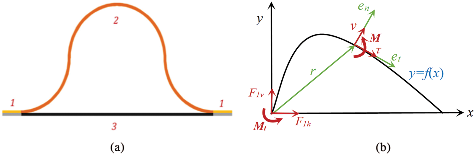
Figure 6: Schematic diagram of the corrugation unit cell and its curve function [67]
Structural analysis is combined with other system-level analyses such as aerodynamic analysis and control analysis [69,70]. The structural equation of motion can be obtained by Newton’s principle, and the stability can be determined by using the Strut diagram based on Mathieu’s equation. Assuming that the structure under consideration is in a state of plane stress, the Lagrangian equation [71] can be used to derive the system equations, and structural nonlinearities can also be considered at the system level, such as piecewise linear stiffness and cubic stiffness. Commercial multibody code LMS Virtual.Lab Motion can be used to perform nonlinear dynamic simulation of flexible multi-body systems.
3.2 Aircraft Dynamics Modeling
The current dynamic modeling of morphing aircrafts can be divided into two categories: (1) the multi-rigid body dynamics model (such as Newton-Euler method [72], Lagrange method [73], and Kane method [74]); (2) the flexible-body dynamics model (such as floating frame of formulation [75] and absolute nodal coordinate formulation [76,77]). Compared with the multi-rigid body dynamics model, the flexible-body dynamics model is closer to the actual engineering conditions and can be applied to the aeroelastic analysis of folding wings, so it has received more attention.
In the calculation and evaluation of the aerodynamic characteristics of morphing aircrafts, Wickenheiser et al. [78] extended Prandtl’s lift line theory to a wing with arbitrary camber and chord length distribution and a non-ideal airfoil. Bowman et al. [79] found that at low speeds, the increase in the camber of the airfoil causes the point of least drag on the lift coefficient-drag coefficient curve to move to the lower right. In contrast, at high speeds, the increasein type camber causes the point of least resistance on the lift coefficient-drag coefficient curve to move to the upper right. Samareh et al. [80] developed an analysis tool using an efficient parameterized model formula, which can automatically generate models of aerodynamic parameters, geometric parameters, and shape change parameters for systems that undergo large deformations. Cho et al. [81] used the Panel method to solve the bionic double-wing problem and compared it with the CFD method. Gao [82] theoretically derived the unsteady aerodynamic characteristics of the two-dimensional airfoil during the morphing process through the analytical solution of the Zhukovsky.
Different from the aeroelastic analysis of conventional wings, the aeroelastic analysis of folding wings requires re-establishing the structural dynamic model and the aerodynamic model at each angle, and coupling them to obtain the aeroelastic model. For example, Snyder et al. [83] studied the flutter characteristics of the Goland folding wingand found that the hinge stiffness of the folding wing has a great influence on the flutter frequency and flutter speed of the morphing wing. Selitrennik et al. [84] proposed an efficient aeroelastic modeling method for rapidly morphing folding wing systems. This method uses virtual mass method to establish the structural dynamic equation of the system, and establishes the aeroelastic equation of the foldable morphing wing by coupling the dynamic equation and CFD technology. Lee et al. [85] proposed a numerical calculation method that can efficiently predict the subcritical limit cycle oscillation of a folding wing. Although the above-mentioned aeroelastic dynamics modeling methods have been successfully applied to the aeroelastic modeling of the foldable variant wing, it is still necessary to carry out repeated as well as non-repetitive structural dynamics modeling for different folding angles in the aeroelastic analysis process. Zhao et al. [86] and Ni et al. [87] used the substructure synthesis and the dipole grid method to construct a parametric aeroelastic model of the folding wing (as shown in Fig. 7), and analyzed the influence of modal damping, folding angle, and hinge stiffness on the dynamics of the folding wing. Huang et al. [88] proposed a parametric aero-servo-elastic modeling method, which efficiently obtained the aero-servo-elastic mathematical model of wings under different folding angles, and realized the design of control law and closed-loop aero-servo for active flutter suppression. Zhan et al. [89], based on the manifold tangent space interpolation method, established a folding wing parameter variable structure dynamic model with the folding angle as a parameter, and coupled the parametric unsteady aerodynamic model based on the dipole grid method to establish the parametric aeroelastic model of folding wings.
Figure 7: Parameterized aeroelastic modeling and flutter analysis for a folding wing [86]
3.3 Aerodynamic Calculation Method
Regarding the current mainstream CFD technology, whether it is solving steady or unsteady flow problems, its control equations are all implemented in the unsteady form through a certain time iterative algorithm [90–92]. The main difference is that in the calculation of the steady flow field, it is the virtual time variable that has no practical significance, while the variable in the evolution of the unsteady flow field is the real time variable that has the exact physical meaning [93,94].
3.3.1 Steady Flow Field Solution Technology
The steady flow solution technology has a longer development process. It has an inherited relationship with the unsteady flow solution technology [95]. Many steady flow field solution techniques are the basis of unsteady flow solutions.
The linear method is based on the theory of potential flow and is most suitable for thin lift surfaces with small angles of attack (such as cruise flight). The panel potential flow method is widely used to simulate the steady aerodynamic behavior in morphing wing design and optimization [96,97]. This method uses singularity panels to replace wing boundaries, such as source panels, bimodal panels, and vortex panels. Lafountain et al. [98] used XFOIL to perform fast and relatively accurate 2D steady-state flow simulations for different morphing configurations, and used arc-controlled morphing wings to maneuver. Woods et al. [99] compared the linear method XFOIL with the open source CFD solver OpenFOAM, and found that the two have very similar aerodynamic performance prediction methods, but the computational cost is only a small part of the CFD solver. Fincham et al. [100] used XFOIL as the source of aerodynamic predictions, and found that the performance of a morphing airfoil (as shown in Fig. 8) is almost close to an ideal airfoil whose shape can be changed arbitrarily.
Figure 8: Example of a NACA 0012 morphed to different cambers through the RBF method [100]
The extended lift line theory decomposes a 3D wing into a series of 2D wing shapes, which is a common selection method. Wickenheiser et al. [78] proposed an extension of the Weissinger method, which extended Prandtl’s lift line theory to wings with arbitrary curvature and chord distribution and non-ideal airfoil cross-sections. Ajaj et al. [101] presented the Zigzag wingbox concept (as shown in Fig. 9) that allows the wing span to be varied by 44% (22% extension and 22% retraction), and used the Tornado code to predict the aerodynamics of morphing wings along the span. Li et al. [102] took the seamless leading edge and trailing edge control surfaces as the research object, and used the Tornado code to calculate the lift coefficient and pitching moment coefficient of the light flexible deformable wing.
Figure 9: Top-view of the Zigzag wingbox concept [101]
Static aeroelastic analysis methods include structural analysis and aerodynamic analysis [103,104]. The structural analysis method usually takes less time than the aerodynamic analysis method. Due to cost considerations, the linear aerodynamic method is preferred when optimizing morphing wings for static aeroelastic analysis. Bilgen et al. [105] proposed a static aeroelastic modeling and optimization method for a variable camber wing. Two cascaded bimorph actuators were used on the top and bottom surfaces of the wing, and they were fixed behind the wing. Then based on XFOIL and ANSYS, a semi-solid variable camber airfoil coupling system was established. The optimization problem of 3D morphing wings is often dealt with by the 3D panel method or the extended lift line theory. Molinari et al. [106] optimized a tailless morphing aircraft driven by MFC based on the 3D panel method. The results showed that the rolling torque was increased by 54%, the pitch moment at 30 m/s was increased by 43%, and the pitch moment at 15 m/s was increased by 378%.
The CFD method is more suitable when the angle of attack is large and the flow shows a strong viscous effect. Woods et al. [99] compared the Open FOAM solver with the XFOIL solver for the morphing structure and found that the calculation results of the two methods werethe most consistent under the 8-degree angle of attack. One of the many difficulties in CFD analysis is the prediction of the change from laminar flow to turbulent flow, which may be related to the flow conditions of the designed morphing wing. Gabor et al. [107] compared the CFD calculation results of the morphing wing (as shown in Fig. 10) with the wind tunnel test results, and found that numerical results of the pressure distribution were consistent with the wind tunnel test results, but they failed to accurately explain the change mechanism of drag in experiments. Although there are some computational difficulties, the CFD is often better than linear methods when performing aero bomb prediction analysis based on a limited number of grids. Spadoni et al. [108] studied various configurations in airfoil design based on static aeroelastic analysis methods, and used Euler equations for flow field calculations. Ismail et al. [109] studied the torsional bending deformation of perimeter reinforced (PR)-compliant wing (as shown in Fig. 11). By solving the 3D incompressible Reynolds Average Navier-Stokes (RANS) shear stress transfer equation, the aerodynamic force was calculated and its aerodynamic characteristics were identified. Studies have shown that the PR-compatible wing can produce a higher nonlinear lift distribution than the PR or rigid wing type. Lyu et al. [110] used the CFD solver sumb to optimize the adaptive deformable trailing edge wing.
Figure 10: Layout of the morphing wing [107]
Figure 11: PR-compliant wing [109]
3.3.2 Unsteady Flow Field Solution Technology
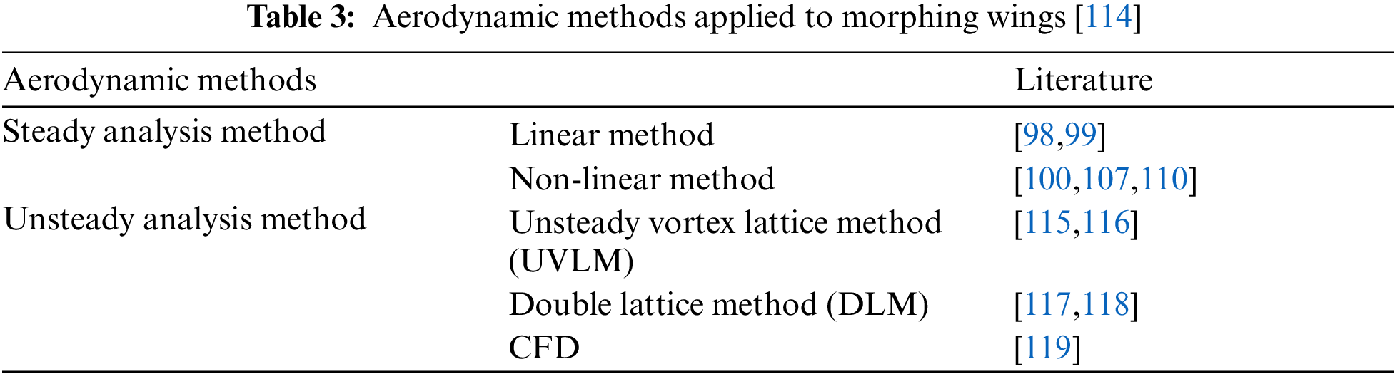
The definition is based on the description of the Euler’s field. If the flow field parameters change with time, which means the derivative of the physical quantity with respect to time is not zero, then this flow can be regarded as unsteady [103,111]. For the flow control, the unsteady characteristics are mainly reflected by the time derivative term. Therefore, in the calculation of the unsteady flow, although the numerical dispersion of the time derivative term is similar to that of the steady flow, the essence of time advancement is different. The sources of unsteady effects can be divided into three categories. The first one is that caused by the instability of the flow itself [112]. Typical phenomena include the shedding and evolution of separation vortices, shock-boundary layer interference oscillations, etc. The second one is that caused by the pulsation of incoming flow, which mainly includes random gust response, pulsating jet flow control, change of incoming flow velocity and direction with time, etc. The third category is the unsteady effect caused by the morphing of the solid wall boundary. Typical phenomena include the turbulence during the flexible vibration of the wing, the multi-body separation turbulence, and the control surface maneuvering deflection turbulence. In fact, a specific unsteady flow is often the result of the combined effects of the above three types of sources. From the perspective of the complexity of the numerical method, the numerical simulation of the first type of problems is easiest to implement, and it is also the basis for the second and third types [113]. Table 3 summarizes the aerodynamic methods applied to morphing wings.
Peters et al. [120] proposed a state-space aerodynamic theory of flexible airfoils, which can be combined with other dynamic codes for time advancement, eigenvalue, or control system design. This theory has been applied to the aeroelastic analysis of flexible airfoils [121]. Murua et al. [122] numerically investigated the effect of chord-wiseflexibility on the dynamic stability of compliant airfoils. A classical two-dimensional aeroelastic model was expanded with an additional degree of freedom to capture time-varying camber deformations, defined by a parabolic bending profile of the mean aerodynamic chord (as shown in Fig. 12). Berci et al. [123] explored the combined aeroelastic behavior and gust response of a flexible airfoil theoretically (as shown in Fig. 13) through simulating the aerodynamic load by Peters’ state space model. This method can also be applied to morphing airfoils [124]. In addition, there are some other aerodynamic theories that take into account the flexibility of the wing [125,126]. For example, Johnson et al. [125] summarized the systematic application of von Kármán and Sears’ extended unsteady thin airfoil theory to general morphing airfoils. The theory proposed by Huang et al. [127] is limited to rigid body motion and can be extended to unstable aerodynamics of thin morphing airfoils.
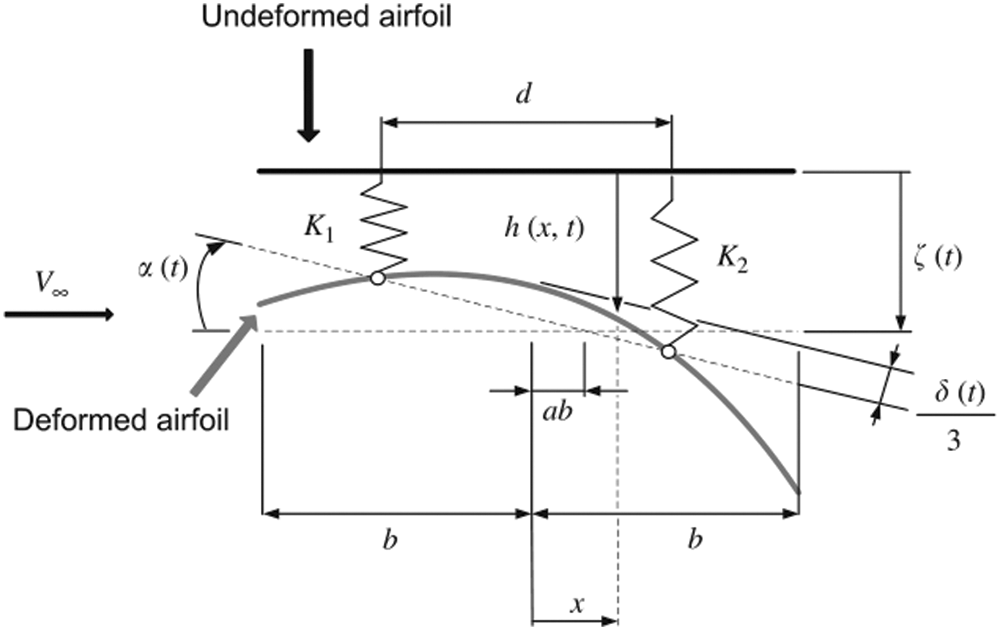
Figure 12: Airfoil camber line with two spring-supported rigid-body (plunge and pitch) and one elastic (camber deformations) degrees of freedom [122]
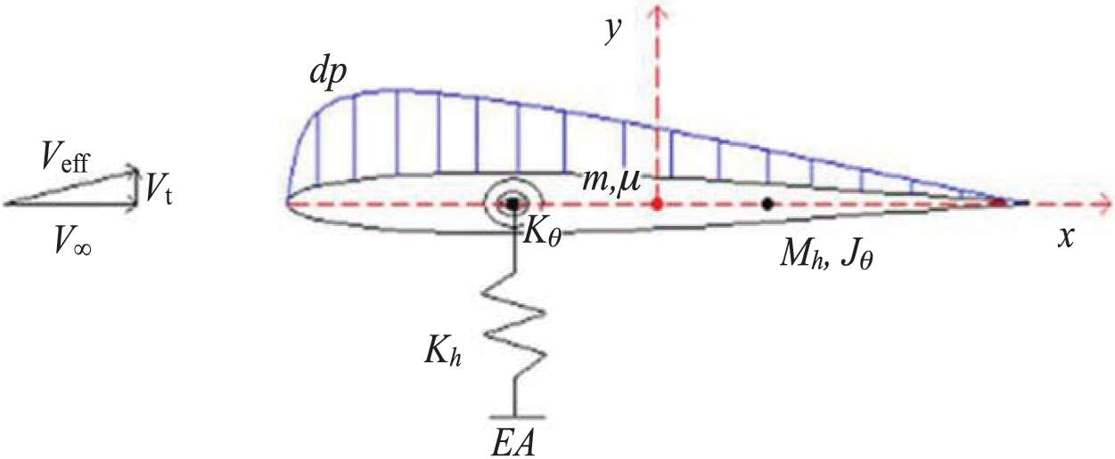
Figure 13: Flexible airfoil: Cross-sectional schematic diagram showing key parameters and load distribution [123]
The unsteady vortex lattice method (UVLM) is often used to simulate the morphing process in the time domain (as shown in Fig. 14 [116]). It is assumed that the flow field is inviscid, incompressible, and non-rotational [128,129]. In the case of morphing wings, the influence coefficient matrix will change, and must be modified and solved at each time step. Therefore, the UVLM can easily adapt to different wing geometries and morphing processes [115]. Ghommem et al. [116] considered active shape morphing in optimizing the flying performance of flapping wings based on the UVLM. The results showed that the spline-based morphing, which requires more design variables to be specified, produces a significant improvement in propulsion efficiency. Ren et al. [117,127] combined the reduced-order UVLM and the Euler-Bernoulli beam theory with transient boundary conditions to develop a first-order state-space aeroelastic model. The results indicated that the critical flutter speed of a variable-span wing is very sensitive to the span length because it has a significant impact on the structural stiffness and aerodynamic characteristics.
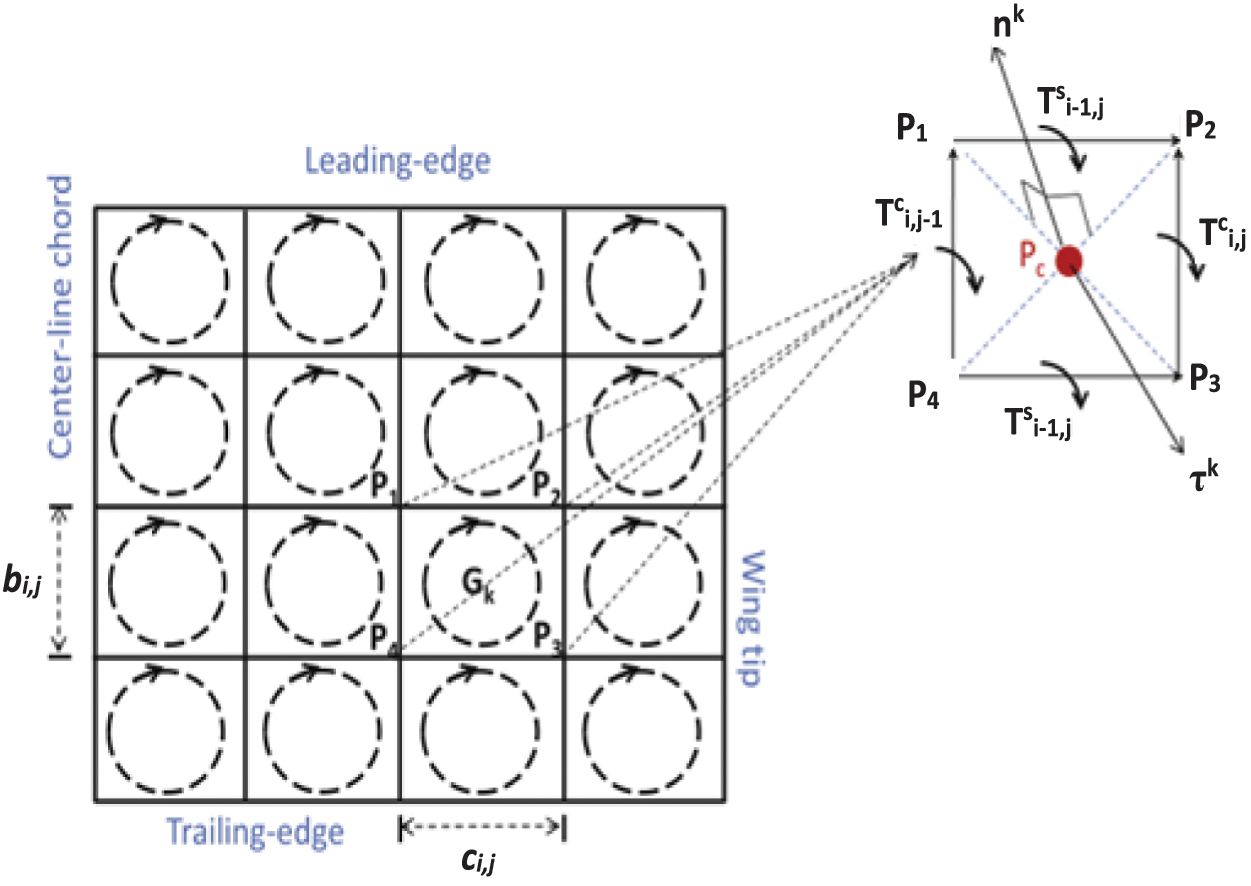
Figure 14: Wing discretization and an example of a typical vortex element [116]
The double lattice method (DLM) is used to simulate aerodynamics in the frequency domain. The DLM is usually used as the first step in aeroelastic analysis [118,130,131]. Castrichini et al. [132] studied a flexible wing folding device for load reduction. The commercial multi-body code LMS Virtual Lab Motion was used to build the structural model, and the aerodynamic influence coefficient matrix was evaluated by the DLM. Shrestha et al. [133] studied the influence of the change of the folding angle on the flutter speed and frequency of awing. The structural and aerodynamic models were created by using MSC.PATRAN Flight Loads. Via changing the folding angle of the outer wing independently of that of the inner wing, a proposal was made to enhance the flutter characteristics of the aluminum folding wing. Pecora et al. [134] were dedicated to studying the aeroelastic stable configuration of the morphing wing trailing edge driven by traditional electromechanical actuators. The unsteady aerodynamic influence coefficient matrix was evaluated by the DLM, and the structural model was established based on the finite element method. The results obtained showed that for the most practical combination of the trailing edge stiffness and the inertia distribution, flutter could be avoided if the actuation chain provides sufficient stiffness. The reduced-order method (ROM) based on the CFD method is very popular in dynamic aeroelasticity. Liu et al. [119] conducted a ROM-based aeroelastic continuous dynamic simulation of a morphing wing. The results showed that the LCO amplitude predicted by the ROM method is very consistent with the direct CFD method, but the phase shift would occur with the development of LCO.
4 Current Status of Aeroelastic Wind Tunnel Test on Morphing Aircrafts
Due to the unsteady aerodynamic characteristics caused by the shape change of the variant structure, great challenges are presented to the prediction technology of the aerodynamic performance and load environment of aircrafts. Compared with the traditional wind tunnel test, the morphing model design needs to consider the consistency of the morphing scale and the response time in the real flight environment. Considering that the characteristic size of the aircraft changes greatly after the morphing, the revision of the similarity theory to the test results requires the establishment of a new test simulation method, and the measurement and evaluation of unsteady aerodynamic characteristics under dynamic morphing conditions have also become a major difficulty.
4.1 Overview of Wind Tunnel Test
The wind tunnel test of the aircraft is to fix the actual aircraft or its reduced model in the ground wind tunnel test environment and blow the airflow at a certain pressure and wind speed, and to use the relative movement of the airflow and the test object to simulate the actual flight situation in the air [135]. The purpose is to form the interaction between the airflow and the model, and then to study the aerodynamic characteristics of the actual aircraft. According to the test object used, it is divided into the physical test and the model test. The former will not be distorted, but it needs more test consumables, sets higher requirements for the test environment, and requires more stringent conditions. The latter is based on similarity theory, performing an experiment with a model that is geometrically similar to the real thing. At the same time, the two flow fields are related to similar criteria, such as Reynolds number, Mach number, and Prandtl number. It should be ensured that the flow field similar to the real flow field is used for testing. The dynamic performance of the aircraft is simulated and tested. Wind tunnels can be classified according to the airflow velocity. Those with an airflow velocity ranging from 0.8 Ma to 1.4 Ma are called transonic wind tunnels; those with an air velocity of about 0.4 Ma to 0.8 Ma are called subsonic wind tunnels [136,137].
In the design stage, the aeroelastic characteristics of the aircraft must be analyzed through wind tunnel tests to verify whether the strength design and performance indicators meet the requirements, and corresponding improvements should be made. The wind tunnel flutter test is carried out before the flight test, so that its results can be used to provide a basis for and reduce the risk of the flight test. In addition, the aeroelastic wind tunnel test also provides support for the verification of advanced aerodynamic/structural coupling design and analysis methods. Taking the development of advanced aircrafts in the United States as an example, the transonic dynamics wind tunnel (TDT) of the Langley Center of NASA was completed in the early 1960s. By 2016, more than 600 wind tunnel tests had been carried out. Most of them are aeroelastic tests, including fixed-wing aircrafts, rotary wing aircrafts, launch vehicles, and other configurations, which have contributed to the aeroelastic design and analysis of the research models, the engineering application of new layouts and new technologies, and the development of numerical calculation methods. Therefore, the aeroelastic wind tunnel test technology is a solid foundation for the research and development of aerospace vehicles.
The main vibration forms of the wind tunnel model can be decomposed into pitch vibration, the roll vibration, and the yaw vibration. The air pulsation (which should be referred to as velocity pulsation) is one of the vibration factors of the wind tunnel test and comes from two aspects. The main frequency of the air pulsation is generally low, and it is easy to be coupled with the low-order natural frequency of the support system. However, the original air pulsation is difficult to reduce. On the other hand, the airflow pulsation caused by the airflow separation phenomenon generated by the model during the test (such as the separation of the model airflow in the high angle of attack test) is unavoidable.
The vibration of the wind tunnel test is mainly improved from two perspectives. One is the improvement on the wind tunnel aerodynamics, and the other is the improvement on the dynamic characteristics of the model support system. It is very difficult to improve the excitation source from the aerodynamic aspect, especially in such cases as modifying the shape of the aircraft model or changing the flow field of the wind tunnel. Therefore, damping vibration by improving the dynamic characteristics of the model support system will be an effective way to solve this problem. According to the principle, the vibration suppression method of the wind tunnel tail support model can be divided into the passive control method based on a damper and the active control method based on the inverse piezoelectric effect of a piezoelectric element.
Similar phenomena refer to physical phenomena that follow the same physical laws and equations. Single-valued conditions are conditions distinguished from the same type of phenomena (conditions that determine the uniqueness of solutions to physical equations), and the similarity criterion is the relationship between certain physical quantities in similar phenomena. The similarity criteria of Reynolds number, Mach number, mass ratio, reduction frequency, etc., are derived from geometric conditions, physical conditions, boundary conditions, and initial conditions. Given the physical equations, we can use the equation analysis method (similar transformation method and integral analogy method) to derive the similarity criterion. If the physical equation is not established, we can then use the dimensional analysis method (Buckingham π theorem) to derive the similarity criterion.
The similarity theory requires that all similar parameters of the model in the model experiment must be completely consistent with the prototype, but it is almost impossible to completely meet the requirements of the similarity theory in the aeroelastic model experiment. Therefore, the local simulation method is adopted to simulate the similar parameters that control the main physical phenomena and processes, and the requirements for other secondary similar parameters are relaxed. The low-speed flutter test generally simulates Reynolds number, mass ratio, and stiffness ratio, whereas the transonic flutter test generally simulates Mach number, mass ratio, and stiffness ratio.
For the high-speed wind tunnel flutter test model, the first three basic scales are: length, density, and dynamic pressure. The length ratio is determined according to the experimental section of the wind tunnel and the actual size, the density ratio is determined according to the air density in the wind tunnel and in the actual flight state, and the dynamic pressure ratio is estimated according to the reachable limit of the stagnant point pressure in front of the wind tunnel and the actual object. The high-speed wind tunnel flutter test is much more difficult than the low-speed wind tunnel flutter test. The reason is that the scale of the high-speed wind tunnel test section is much smaller than that of the low-speed wind tunnel, the test time is shorter, and the strength requirements of the test model are stricter.
4.3 Design of Wind Tunnel Experimental Model
In recent years, in the field of structural optimization design, the respective advantages of comprehensive sensitivity methods and genetic algorithms have complemented each other, forming a sensitivity/genetic hybrid optimization design method with efficient global search capabilities. In the design process of the flutter model, the method can be applied not only to the final modification of the structure, but also to multiple links in the entire design process. Neal et al. [137,138] designed the wind tunnel experimental models of morphing aircrafts to achieve five goals: establishing a quasi-steady model of large morphing aircrafts, optimizing research on ‘efficient flight layout’, establishing transient models for fast-morphing aircrafts, conducting evaluation research on ‘morphing as a maneuver control device’, and simulating the flight control of morphing aircrafts. There are two types of morphing that can occur in the final experimental model. The first type is to adapt the aircraft to large deformations for different tasks, including changes in extension, sweep angle, and tail layout. The second type is to enable the aircraft to maneuver. For the controlled morphing of the wing including wing torsion, the combination of the two types of morphing can significantly enhance the morphing ability of the experimental model. Henry et al. [139] used wind tunnel experiments to study the effect of variable aspect ratio on the stability of UAVs. The calculated stability coefficient verified that the variable aspect ratio wing can maintain stability when the span change symmetrically, and the roll mode becomes more stable as the span increases. In addition, a wind tunnel experiment verified that asymmetrical elongation can generate a rolling moment that controls the rolling maneuver. Hall et al. [140] studied the possibility of improving the flight performance of micro-aircrafts by changing the sweep angle. High aerodynamic efficiency and the ability to launch quickly and easily were required. To achieve these goals, a variable swept-back wing was investigated.
An exceptionally fast morphing rate will have a great impact on the unsteady aerodynamic characteristics, stability characteristics, and flight control of the aircraft during the morphing process. Rapid morphing also sets higher requirements for deformable materials, structures, actuation systems, and morphing control. Conversely, a too slow morphing rate will bring additional costs and disadvantages to the deformable materials, structures, actuation systems, and flight control, and cannot meet the requirements of the flight mission and the environment when the overall flight performance is required to respond quickly. Therefore, it is necessary to comprehensively consider factors such as aerodynamics, flight control, materials, structure, and action, and carry out comprehensive calculations and experimental analysis, so as to obtain a realistic and feasible morphing rate. For example, Nextgen’s MFX-1 disclosed that the time required to deform the wing is 15 s, the F-111 variable sweep speed can reach 3.8°/s, and the F-14 variable sweep speed can reach 7.5°/s. It is still unclear whether the designer chooses such a morphing rate out of the consideration of the structural realization factors and flight mission requirements, or out of the intention to avoid causing unsteady aerodynamics and related flight control problems. However, in the preliminary analysis of the morphing of birds and variable-sweeping aircrafts, the safe morphing rate should have a certain relationship with the incoming flow velocity and the characteristic scale of the aircraft.
This paper has reviewed the development process and the current status of aeroelastic issues, numerical simulations, and wind tunnel test of morphing aircrafts. It aims at discussing the potential aeroelastic common problems in the morphing process, and comprehensively elaborates the key problems faced by the morphing aircrafts and the progress. In addition, the wind tunnel test technology has been analyzed in detail. The concept, origin, and development of aircraft morphing technology, aeroelastic numerical simulation, and aeroelastic wind tunnel test have been summarized, which provide background introduction and pavement for the follow-up review.
The aeroelastic problems and their solutions in the development of high-performance UAVs have been explained from three aspects: the development history of aeroelasticity, the classification of aeroelastic problems, and the bottlenecks of the aerodynamic characteristics of morphing aircrafts. The technical bottlenecks of the aerodynamic characteristics of morphing aircrafts are mainly embodied in the evaluation of aerodynamic characteristics, mechanism, and applicable unsteady dynamic aerodynamic modeling during the morphing process. Unsteady aerodynamic forces have an important impact on the handling characteristics of the aircraft, control law design, and flight safety. Due to this reason, it is necessary to study the unsteady aerodynamic characteristics, dynamic characteristics, and generation mechanism of the typical morphing methods during the morphing process, to establish the unsteady dynamic aerodynamic model, and to develop the analysis and evaluation method of the stability characteristics.
The current research status of aeroelastic numerical simulation of high-performance UAVs has been described from four aspects: structural analysis of morphing, modeling of flight dynamics, computational mesh deformation technology, and aerodynamic calculation methods. Traditional aeroelastic problems are divided into static aeroelastic problems and dynamic aeroelastic problems. They mainly focus on the stability of elastic structures under the combined action of the inertial force, the elastic force, and the aerodynamic force. With the application of the fly-by-wire control technology in aircrafts, the servo aeroelasticity has gradually emerged, and the research on hypersonic aircrafts and the thermo aeroelasticity has also been paid attention to. For high-speed aircrafts, the transonic problem is the speed range that all will face. Therefore, the transonic aeroelasticity is a matter of widespread concern. The military aircraft, micro-aircraft, and fluid machinery also involve the aeroelastic problem under high angle of attack separated flow. Both transonic aeroelastic problems and high angle of attack aeroelastic problems belong to nonlinear dynamic problems. The corresponding numerical simulations still have many aspects (such as more exact computing methods, less computing time, multi-physics simulations) to be studied and explored. In the future, these problems should be deeply investigated to promote the development of morphing UAVs.
The research status of the aeroelastic wind tunnel test of morphing aircrafts has been described from three aspects: the wind tunnel test, the similarity law theory, and the wind tunnel test model design. Due to the unsteady aerodynamic characteristics caused by the shape change of the morphing structure, great challenges are presented to the prediction technology of the aerodynamic performance and load environment of the aircrafts. Compared with the traditional wind tunnel test, the morphing model design needs to consider the consistency of the morphing scale and the response time in the real flight conditions. Considering that the characteristic size of the aircraft changes greatly after the morphing, similar theories have little effect on the test results. The correction requires the establishment of a suitable test simulation method, and the measurement and evaluation of unsteady aerodynamic characteristics under dynamic morphing conditions have also become a major difficulty. In the process of dynamic morphing, there are great difficulties in wind tunnel experiments. At present, there are more tests to examine steady or quasi-steady aerodynamic characteristics under different morphing states, but less to examine dynamic unsteady aerodynamic characteristics in the continuous morphing process. Therefore, testing dynamic unsteady aerodynamic characteristics is of interest and value for promoting the development of morphing UAVs.
Funding Statement: The authors received no specific funding for this study.
Conflicts of Interest: The authors declare that they have no conflicts of interest to report regarding the present study.
References
1. Vasista, S., Riemenschneider, J., Monner, H. P. (2015). Design and testing of a compliant mechanism-based demonstrator for a droop-nose morphing device. 23rd AIAA/AHS Adaptive Structures Conference, 1049. Kissimmee, Florida. [Google Scholar]
2. Sun, J., Guan, Q., Liu, Y., Leng, J. (2016). Morphing aircraft based on smart materials and structures: A state-of-the-art review. Journal of Intelligent Material Systems and Structures, 27(17), 2289–2312. DOI 10.1177/1045389X16629569. [Google Scholar] [CrossRef]
3. Lei, Y., Li, X., Zhang, L. (2019). Experimental study on pat system for long-distance laser communications between fixed-wing aircrafts. Photonic Sensors, 9(2), 170–178. DOI 10.1007/s13320-018-0522-9. [Google Scholar] [CrossRef]
4. Yin, W. (2010). Stiffness requirement of flexible skin for variable trailing-edge camber wing. Science China Technological Sciences, 53(4), 1077–1081. DOI 10.1007/s11431-009-0408-6. [Google Scholar] [CrossRef]
5. Monner, H. P. (2001). Realization of an optimized wing camber by using form variable flap structures. Aerospace Science and Technology, 5(7), 445–455. DOI 10.1016/S1270-9638(01)01118-X. [Google Scholar] [CrossRef]
6. Grigorie, T. L., Popov, A. V., Botez, R. M. (2012). Design and experimental validation of a control system for a morphing wing. AIAA Atmospheric Flight Mechanics Conference, 4639. Minneapolis, MI, USA. [Google Scholar]
7. Popov, A. V., Labib, M., Fays, J., Botez, R. M. (2008). Closed-loop control simulations on a morphing wing. Journal of Aircraft, 45(5), 1794–1803. DOI 10.2514/1.37073. [Google Scholar] [CrossRef]
8. Popov, A. V., Grigorie, L. T., Botez, R. M., Mamou, M., Mébarki, Y. (2010). Closed-loop control validation of a morphing wing using wind tunnel tests. Journal of Aircraft, 47(4), 1309–1317. DOI 10.2514/1.47281. [Google Scholar] [CrossRef]
9. Sofia, A. Y. N., Meguid, S. A., Tan, K. T., Yeo, W. K. (2010). Shape morphing of aircraft wing: Status and challenges. Materials & Design, 31(3), 1284–1292. DOI 10.1016/j.matdes.2009.09.011. [Google Scholar] [CrossRef]
10. Weidong, L. (2014). Research on key technology of morphing wing (Ph.D. Thesis). Nanjing University of Aeronautics and Astronautics, Nanjing, China. [Google Scholar]
11. Grogorie, L., Popov, A., Botez, R. M. (2013). Control of actuation system based smart material actuators in a morphing wing experimental model. AIAA Atmospheric Flight Mechanics (AFM) Conference, 4918. Minneapolis, Minnesota. [Google Scholar]
12. Gupta, S. G., Ghonge, M. M., Jawandhiya, P. M. (2013). Review of unmanned aircraft system (UAS). International Journal of Advanced Research in Computer Engineering & Technology, 2(4), 1646–1658. DOI 10.2139/ssrn.3451039. [Google Scholar] [CrossRef]
13. Wang, Z., Sun, Y., Yang, D., Guo, S. (2012). Active control using control allocation for UAVs with seamless morphing wing. Third International Conference on Smart Materials and Nanotechnology in Engineering, Shenzhen, China. [Google Scholar]
14. Kuzmina, S., Amiryants, G., Schweiger, J., Cooper, J., Amprikidis, M. et al. (2002). Review and outlook on active and passive aeroelastic design concepts for future aircraft. ICAS 2002 Congress, pp. 8–13. Toronto, Canada. [Google Scholar]
15. Bowman, J., Sanders, B., Cannon, B., Kudva, J., Weisshaar, T. (2007). Development of next generation morphing aircraft structures. 48th AIAA/ASME/ASCE/AHS/ASC Structures, Structural Dynamics, and Materials Conference, 1730. Hawaii, USA. [Google Scholar]
16. Zhu, L., Sun, G., Li, H., Dong, M. (2018). Intelligent and flexible morphing wing technology: A review. Journal of Mechanical Engineering, 54(14), 28–42. DOI 10.3901/JME.2018.14.028. [Google Scholar] [CrossRef]
17. Huang, J. (2018). Mechanical performances of a novel honeycomb design with zero poisson’s ratio and its application in camber morphing wings (Ph.D. Thesis). Harbin Institute of Technology, Harbin, China. [Google Scholar]
18. Li, F. (2009). Research on adaptive wing structures based on Niti SMA actuator (M.D. Thesis). Nanjing University of Aeronautics and Astronautics, Nanjing, China. [Google Scholar]
19. Liu, S., Ge, W., Li, K., Zhu, P. (2008). Optimal structural design of a three-dimensional morphing aircraft wing based on strut and cable ground structure. Mechanical Science and Technology for Aerospace Engineering, 27(10), 1191–1194. DOI 10.3321/j.issn:1003-8728.2008.10.015. [Google Scholar] [CrossRef]
20. Kou, J., Zhang, W. (2021). Data-driven modeling for unsteady aerodynamics and aeroelasticity. Progress in Aerospace Sciences, 125(1–2), 100725. DOI 10.1016/j.paerosci.2021.100725. [Google Scholar] [CrossRef]
21. Wang, I., Gibbs, S. C., Dowell, E. H. (2012). Aeroelastic model of multi-segmented folding wings: Theory and experiment. Journal of Aircraft, 49(3), 911–921. DOI 10.2514/1.C031589. [Google Scholar] [CrossRef]
22. Xiao, J., Gu, C. G. (2010). Numerical simulation for aeroelasticity based on a fully implicit strong coupling algorithm. YuhangXuebao/Journal of Astronautics, 31, 2471–2476. DOI 10.3873/j.issn.1000-1328.2010.11.006. [Google Scholar] [CrossRef]
23. Zhou, X., Li, S. (2013). A new mesh deformation method based on disk relaxation algorithm with pre-displacement and post-smoothing. Journal of Computational Physics, 235(6), 199–215. DOI 10.1016/j.jcp.2012.10.024. [Google Scholar] [CrossRef]
24. Ajaj, R. M., Friswell, M. I., Bourchak, M., Harasani, W. (2016). Span morphing using the GNATSpar wing. Aerospace Science and Technology, 53(4), 38–46. DOI 10.1016/j.ast.2016.03.009. [Google Scholar] [CrossRef]
25. Vos, R., Gürdal, Z., Abdalla, M. (2010). Mechanism for warp-controlled twist of a morphing wing. Journal of Aircraft, 47(2), 450–457. DOI 10.2514/1.39328. [Google Scholar] [CrossRef]
26. Colorado, J., Barrientos, A., Rossi, C., Parra, C. (2012). Inertial attitude control of a bat-like morphing-wing air vehicle. Bioinspiration & Biomimetics, 8(1), 016001. DOI 10.1088/1748-3182/8/1/016001. [Google Scholar] [CrossRef]
27. Vasista, S., de Gaspari, A., Ricci, S., Riemenschneider, J., Monner, H. P. et al. (2016). Compliant structures-based wing and wingtip morphing devices. Aircraft Engineering and Aerospace Technology, 88(2), 311–330. DOI 10.1108/AEAT-02-2015-0067. [Google Scholar] [CrossRef]
28. Witteveen, J. A. S., Bijl, H. (2009). Explicit mesh deformation using inverse distance weighting interpolation. 19th AIAA Computational Fluid Dynamics, 3996. San Antonio, Texas. [Google Scholar]
29. Yang, Z., Zhao, L. (2009). Aeroelasticity of aircraft. Xi’an, China: Northwestern Polytechnical University Press. [Google Scholar]
30. Yang, N., Wang, N., Zhang, X., Liu, W. (2016). Nonlinear flutter wind tunnel test and numerical analysis of folding fins with freeplay nonlinearities. Chinese Journal of Aeronautics, 29(1), 144–159. DOI 10.1016/j.cja.2015.12.011. [Google Scholar] [CrossRef]
31. Zhang, W., Lv, S., Ni, Y. (2018). Parametric aeroelastic modeling based on component modal synthesis and stability analysis for horizontally folding wing with hinge joints. Nonlinear Dynamics, 92(2), 169–179. DOI 10.1007/s11071-017-3956-5. [Google Scholar] [CrossRef]
32. Tang, D., Grasch, A., Dowell, E. H. (2010). Gust response for flexibly suspended high-aspect ratio wings. AIAA Journal, 48(10), 2430–2444. DOI 10.2514/1.J050309. [Google Scholar] [CrossRef]
33. Guruswamy, G. P. (1990). Unsteady aerodynamic and aeroelastic calculations for wings using Euler equations. AIAA Journal, 28(3), 461–469. DOI 10.2514/3.10415. [Google Scholar] [CrossRef]
34. Tang, C., Wang, D. (2019). Study on analytic procedure of static aeroelastic characteristics of hypersonic aircraft. Aircraft Design, 39(3), 6–12. DOI 10.19555/j.cnki.1673-4599.2019.03.002. [Google Scholar] [CrossRef]
35. Yuan, K., Tian, H. (2020). Research progress on aeroelasticity of high speed vehicles. Tactical Missile Technology, 3, 1–7. [Google Scholar]
36. Tian, W. (2018). Studies on wing nonlinear aeroelasticity in hypersonic flow (Ph.D. Thesis). Northwestern Polytechnical University, Xi’an, China. [Google Scholar]
37. Yang, Z., Tian, W., Gu, Y., He, S. (2016). Advance in the study on wing aeroelasticity with concentrated nonlinearity. Acta Aeronautica et AstronauticaSinica, 37, 2013–2044. DOI 10.7527/S1000-6893.2016.0140. [Google Scholar] [CrossRef]
38. Jiang, Y. (2009). Aeroelastic studies on a folding wing configuration (M.D. Thesis). Nanjing University of Aeronautics and Astronautics, Nanjing, China. [Google Scholar]
39. Chi, S. (2011). Theoretical and computational flutter study for folding wing configuration (M.D. Thesis). Nanjing University of Aeronautics and Astronautics, Nanjing, China. [Google Scholar]
40. Belytschko, T. (1980). Fluid-structure interaction. Computers & Structures, 12(4), 459–469. DOI 10.1016/0045-7949(80)90121-2. [Google Scholar] [CrossRef]
41. Wright, J. R., Cooper, J. E. (2018). Introduction to aircraft aeroelasticity and loads. USA: John Wiley & Sons. [Google Scholar]
42. Drela, M. (1989). XFOIL: An analysis and design system for low reynolds number airfoils. In: Mueller, T. J. (Eds.Low reynolds number aerodynamics. Berlin, Germany: Springer. [Google Scholar]
43. Zhao, Y. (2009). Stability of a two-dimensional airfoil with time-delayed feedback control. Journal of Fluids and Structures, 25(1), 1–25. DOI 10.1016/j.jfluidstructs.2008.03.003. [Google Scholar] [CrossRef]
44. Su, H. Q., Huang, Z., Bao, X. X., Shi, H. W., Song, J. (2015). Morphing process research of UAV with PID controller. Procedia Engineering, 99(6), 873–877. DOI 10.1016/j.proeng.2014.12.615. [Google Scholar] [CrossRef]
45. Qin, N., Liu, X., Xia, H. (2005). An efficient moving grid algorithm for large deformation. Modern Physics Letters B, 19(28n29), 1499–1502. DOI 10.1142/S0217984905009754. [Google Scholar] [CrossRef]
46. Raither, W., Heymanns, M., Bergamini, A., Ermanni, P. (2013). Morphing wing structure with controllable twist based on adaptive bending-twist coupling. Smart Materials & Structures, 22(6), 65017–65031. DOI 10.1088/0964-1726/22/6/065017. [Google Scholar] [CrossRef]
47. Weisshaar, T. A. (2013). Morphing aircraft systems: Historical perspectives and future challenges. Journal of Aircraft, 50(2), 337–353. DOI 10.2514/1.C031456. [Google Scholar] [CrossRef]
48. Sanders, B., Eastep, F. E., Forster, E. (2003). Aerodynamic and aeroelastic characteristics of wings with conformal control surfaces for morphing aircraft. Journal of Aircraft, 40(1), 94–99. DOI 10.2514/2.3062. [Google Scholar] [CrossRef]
49. McNamara, J. J., Friedmann, P. P. (2011). Aeroelastic and aerothermoelastic analysis in hypersonic flow: Past, present, and future. AIAA Journal, 49(6), 1089–1122. DOI 10.2514/1.J050882. [Google Scholar] [CrossRef]
50. Attorni, A., Cavagna, L., Quaranta, G. (2011). Aircraft T-tail flutter predictions using computational fluid dynamics. Journal of Fluids and Structures, 27(2), 161–174. DOI 10.1016/j.jfluidstructs.2010.11.003. [Google Scholar] [CrossRef]
51. Wu, K., Kim, T. H., Kim, H. (2020). Theoretical and numerical analyses of aerodynamic characteristics on shock vector control. Journal of Aerospace Engineering, 33(5), 04020050. DOI 10.1061/(ASCE)AS.1943-5525.0001169. [Google Scholar] [CrossRef]
52. Mcnamara, J. J., Crowell, A. R., Friedmann, P. P., Glaz, B., Gogulapati, A. (2010). Approximate modeling of unsteady aerodynamics for hypersonic aeroelasticity. Journal of Aircraft, 47(6), 1932–1945. DOI 10.2514/1.C000190. [Google Scholar] [CrossRef]
53. Heeg, J., Zeiler, T., Pototzky, A., Spain, C., Engelund, W. (2013). Aerothermoelastic analysis of a NASP demostrator model. 34th Structures, Structural Dynamics and Materials Conference, 1366. La Jolla, CA, USA. [Google Scholar]
54. Hieronymus, T. L. (2016). Flight feather attachment in rock pigeons (Columba liviaCovert feathers and smooth muscle coordinate a morphing wing. Journal of Anatomy, 229(5), 631–656. DOI 10.1111/joa.12511. [Google Scholar] [CrossRef]
55. Nicoli, M., Castro, M., Cuerno, R. (2008). Unified moving-boundary model with fluctuations for unstable diffusive growth. Physical Review E, 78(2), 021601. DOI 10.1103/PhysRevE.78.021601. [Google Scholar] [CrossRef]
56. Cole, S. R., Noll, T. E., Perry III, B. (2003). Transonic dynamics tunnel aeroelastic testing in support of aircraft development. Journal of Aircraft, 40(5), 820–831. DOI 10.2514/2.6873. [Google Scholar] [CrossRef]
57. Henneron, T., Pierquin, A., Clenet, S. (2019). Mesh deformation based on radial basis function interpolation applied to low-frequency electromagnetic problem. IEEE Transactions on Magnetics, 55(6), 1–4. DOI 10.1109/TMAG.2019.2896623. [Google Scholar] [CrossRef]
58. Liu, T. (2004). Geometric and kinematic aspects of image-based measurements of deformable bodies. AIAA Journal, 42(9), 1910–1920. DOI 10.2514/1.1960. [Google Scholar] [CrossRef]
59. Rendall, T., Allen, C. B. (2009). Efficient mesh motion using radial basis functions with data reduction algorithms. Journal of Computational Physics, 228(17), 6231–6249. DOI 10.1016/j.jcp.2009.05.013. [Google Scholar] [CrossRef]
60. Shaw, A. D., Dayyani, I., Friswell, M. I. (2015). Optimisation of composite corrugated skins for buckling in morphing aircraft. Composite Structures, 119(9), 227–237. DOI 10.1016/j.compstruct.2014.09.001. [Google Scholar] [CrossRef]
61. Anandarajah, A. (2010). Finite element analysis of solids and structures. In: Computational methods in elasticity and plasticity, pp. 97–188. DOI 10.1007/978-1-4419-6379-6_5. [Google Scholar] [CrossRef]
62. Cordero-Gracia, M., Gomez, M., Ponsin, J., Valero, E. (2012). An interpolation tool for aerodynamic mesh deformation problems based on octree decomposition. Aerospace Science and Technology, 23(1), 93–107. DOI 10.1016/j.ast.2011.06.002. [Google Scholar] [CrossRef]
63. Stadler, D., Kosel, F., Čelič, D., Lipej, A. (2011). Mesh deformation based on artificial neural networks. International Journal of Computational Fluid Dynamics, 25(8), 439–448. DOI 10.1080/10618562.2011.619500. [Google Scholar] [CrossRef]
64. Degand, C., Farhat, C. (2002). A three-dimensional torsional spring analogy method for unstructured dynamic meshes. Computers & Structures, 80(3–4), 305–316. DOI 10.1016/S0045-7949(02)00002-0. [Google Scholar] [CrossRef]
65. Ermakova, A., Dayyani, I. (2017). Shape optimisation of composite corrugated morphing skins. Composites Part B: Engineering, 115(9), 87–101. DOI 10.1016/j.compositesb.2016.10.029. [Google Scholar] [CrossRef]
66. Dayyani, I., Friswell, M. I., Ziaei-Rad, S., Saavedra Flores, E. I. (2013). Equivalent models of composite corrugated cores with elastomeric coatings for morphing structures. Composite Structures, 104(3), 281–292. DOI 10.1016/j.compstruct.2013.04.034. [Google Scholar] [CrossRef]
67. Dayyani, I., Friswell, M. I., Saavedra Flores, E. I. (2014). A general super element for a curved beam. International Journal of Solids and Structures, 51(17), 2931–2939. DOI 10.1016/j.ijsolstr.2014.04.021. [Google Scholar] [CrossRef]
68. Dowell, E. H., Tang, D., Attar, P. (2010). Nonlinear aeroelastic study for folding wing structures. AIAA Journal, 48(10), 2187–2195. DOI 10.2514/1.44868. [Google Scholar] [CrossRef]
69. Ai, T., Xu, B., Xiang, C., Fan, W., Zhang, Y. (2020). Aerodynamic analysis and control for a novel coaxial ducted fan aerial robot in ground effect. International Journal of Advanced Robotic Systems, 17(4), 172988142095302. DOI 10.1177/1729881420953026. [Google Scholar] [CrossRef]
70. Sotoudeh, Z., Hodges, D., Chang, C. (2015). Validation studies for aeroelastic trim and stability analysis of highly flexible aircraft. Journal of Aircraft, 47(4), 1240–1247. DOI 10.2514/1.46974. [Google Scholar] [CrossRef]
71. Arrieta, A. F., Bilgen, O., Friswell, M. I., Ermanni, P. (2013). Modelling and configuration control of wing-shaped bi-stable piezoelectric composites under aerodynamic loads. Aerospace Science and Technology, 29(1), 453–461. DOI 10.1016/j.ast.2013.05.004. [Google Scholar] [CrossRef]
72. Yue, T., Wang, L., Ai, J. (2013). Longitudinal linear parameter varying modeling and simulation of morphing aircraft. Journal of Aircraft, 50(6), 1673–1681. DOI 10.2514/1.C031316. [Google Scholar] [CrossRef]
73. Shi, R., Song, J. (2013). Dynamics and control for an in-plane morphing wing. Aircraft Engineering and Aerospace Technology, 85(1), 24–31. DOI 10.1108/00022661311294094. [Google Scholar] [CrossRef]
74. Obradovic, B., Subbarao, K. (2011). Modeling of flight dynamics of morphing wing aircraft. Journal of Aircraft, 48(2), 391–402. DOI 10.2514/1.C000269. [Google Scholar] [CrossRef]
75. Shabana, A., Wang, G. (2018). Durability analysis and implementation of the floating frame of reference formulation. Proceedings of the Institution of Mechanical Engineers, 232(3), 295–313. DOI doi.org/10.1177/1464419317731707. [Google Scholar]
76. Li, H., Liang, J., Wu, S., Liu, Q., Zhang, W. (2020). Dynamics modeling and experiment of a flexible capturing mechanism in a space manipulator. Chinese Journal of Theoretical and Applied Mechanics, 52(5), 1465–1474. DOI 10.6052/0459-1879-20-106. [Google Scholar] [CrossRef]
77. Guo, X., Jin, Y., Tian, Q. (2020). Dynamics analysis of stochastic spatial flexible multibody system. Chinese Journal of Theoretical and Applied Mechanics, 52(6), 1730–1742. DOI 10.6052/0459-1879-20-273. [Google Scholar] [CrossRef]
78. Wickenheiser, A., Garcia, E. (2007). Aerodynamic modeling of morphing wings using an extended lifting-line analysis. Journal of Aircraft, 44(1), 10–16. DOI 10.2514/1.18323. [Google Scholar] [CrossRef]
79. Bowman, J., Sanders, B., Weissh, T. (2002). Evaluating the impact of morphing technologies on aircraft performance. 43rd AIAA/ASME/ASCE/AHS/ASC Structures, Structural Dynamics, and Materials Conference, 1631. Denver, Colorado, USA. [Google Scholar]
80. Samareh, J. A., Chwalowski, P., Horta, L. G., Piatak, D. J., Mcgowan, A. M. R. (2007). Integrated aerodynamic/structural/dynamic analyses of aircraft with large shape changes. 48th AIAA/ASME/ASCE/AHS/ASC Structures, Structural Dynamics, and Materials Conference, 2346. Hawaii, USA. [Google Scholar]
81. Cho, J., Lee, H., Han, C. (2006). Unsteady aerodynamics of dual biofoils. 24th AIAA Applied Aerodynamics Conference, 2841. DOI 10.2514/6.2006-2841. [Google Scholar] [CrossRef]
82. Gao, Y. (2021). Study on the unsteady aerodynamics characteristics for the morphing airfoil (Ph.D. Thesis). University of Science and Technology of China, Hefei, China. [Google Scholar]
83. Snyder, M. P., Sanders, B., Eastep, F. E., Frank, G. J. (2009). Vibration and flutter characteristics of a folding wing. Journal of Aircraft, 46(3), 791–799. DOI 10.2514/1.34685. [Google Scholar] [CrossRef]
84. Selitrennik, E., Karpel, M., Levy, Y. (2012). Computational aeroelastic simulation of rapidly morphing air vehicles. Journal of Aircraft, 49(6), 1675–1686. DOI 10.2514/1.C031041. [Google Scholar] [CrossRef]
85. Lee, D., Chen, P. (2006). Nonlinear aeroelastic studies on a folding wing configuration with free-play hinge nonlinearity. 47th AIAA/ASME/ASCE/AHS/ASC Structures, Structural Dynamics, and Materials Conference, 1734. Newport: Rhod Island, USA. [Google Scholar]
86. Zhao, Y., Hu, H. (2012). Parameterized aeroelastic modeling and flutter analysis for a folding wing. Journal of Sound and Vibration, 331(2), 308–324. DOI 10.1016/j.jsv.2011.08.028. [Google Scholar] [CrossRef]
87. Ni, Y., Hou, C., Wan, X., Zhao, M. (2015). Parametric aeroelastic modeling and flutter analysis for a folding wing. Journal of Northwestern Polytechnical University, 33, 788–793. DOI 10.3969/j.issn.1000-2758.2016.03.009. [Google Scholar] [CrossRef]
88. Huang, R., Yang, Z., Yao, X., Zhao, Y., Hu, H. (2019). Parameterized modeling methodology for efficient aeroservoelastic analysis of a morphing wing. AIAA Journal, 57(12), 5543–5552. DOI 10.2514/1.J058211. [Google Scholar] [CrossRef]
89. Zhan, J., Zhou, X., Huang, R. (2021). Parametric aeroelastic modeling of folding wing based on manifold tangent space interpolation. Chinese Journal of Theoretical and Applied Mechanics, 53(4), 1103–1113. DOI 10.6052/0459-1879-20-376. [Google Scholar] [CrossRef]
90. Lo, S., Wang, W. (2005). Generation of tetrahedral mesh of variable element size by sphere packing over an unbounded 3D domain. Computer Methods in Applied Mechanics and Engineering, 194(48–49), 5002–5018. DOI 10.1016/j.cma.2004.11.022. [Google Scholar] [CrossRef]
91. He, D., Ekere, N. N., Cai, L. (1999). Computer simulation of random packing of unequal particles. Physical Review E, 60(6), 7098–7104. DOI 10.1103/PhysRevE.60.7098. [Google Scholar] [CrossRef]
92. Gupta, K. K., Voelker, L. S. (2012). Aeroelastic simulation of hypersonic flight vehicles. AIAA Journal, 50(3), 717–723. DOI 10.2514/1.J051386. [Google Scholar] [CrossRef]
93. Lafleur, J., Olds, J., Braun, R. (2005). Daedalon: A revolutionary morphing spacecraft design for planetary exploration. 1st Space Exploration Conference: Continuing the Voyage of Discovery, 2771. DOI 10.2514/6.2005-2771. [Google Scholar] [CrossRef]
94. Ferlauto, M., Marsilio, R. (2018). Numerical simulation of the unsteady flowfield in complete propulsion systems. Advances in Aircraft and Spacecraft Science, 5, 349–362. [Google Scholar]
95. Popov, A. V., Grigorie, L. T., Botez, R., Mamou, M., Mébarki, Y. (2010). Real time morphing wing optimization validation using wind-tunnel tests. Journal of Aircraft, 47(4), 1346–1355. DOI 10.2514/1.47431. [Google Scholar] [CrossRef]
96. Li, S., Zhao, L., Liu, Y. (2008). Computer simulation of random sphere packing in an arbitrarily shaped container. Computers, Materials & Continua, 7(2), 109–118. DOI 10.3970/cmc.2008.007.109. [Google Scholar] [CrossRef]
97. Zhou, X., Li, S. (2015). A novel three-dimensional mesh deformation method based on sphere relaxation. Journal of Computational Physics, 298(2), 320–336. DOI 10.1016/j.jcp.2015.05.046. [Google Scholar] [CrossRef]
98. Lafountain, C., Cohen, K., Abdallah, S. (2012). Use of XFOIL in design of camber-controlled morphing UAVs. Computer Applications in Engineering Education, 20(4), 673–680. DOI 10.1002/cae.20437. [Google Scholar] [CrossRef]
99. Woods, B. K. S., Fincham, J. H. S., Friswell, M. I. (2014). Aerodynamic modelling of the fish bone active camber morphing concept. Proceedings of the RAeS Applied Aerodynamics Conference, 2224. Bristol, UK. [Google Scholar]
100. Fincham, J. H. S., Friswell, M. I. (2015). Aerodynamic optimization of a camber morphing aerofoil. Aerospace Science and Technology, 43(9), 245–255. DOI 10.1016/j.ast.2015.02.023. [Google Scholar] [CrossRef]
101. Ajaj, R. M., Flores, E. I. S., Friswell, M. I., Allegri, G., Woods, B. K. S. et al. (2013). The Zigzag wingbox for a span morphing wing. Aerospace Science and Technology, 28(1), 364–375. DOI 10.1016/j.ast.2012.12.002. [Google Scholar] [CrossRef]
102. Li, D., Guo, S., Aburass, T. O., Yang, D., Xiang, J. (2016). Active control design for an unmanned air vehicle with a morphing wing. Aircraft Engineering and Aerospace Technology, 88(1), 168–177. DOI 10.1108/AEAT-12-2013-0234. [Google Scholar] [CrossRef]
103. Zhang, Z., Gil, A. J., Hassan, O., Morgan, K. (2008). The simulation of 3D unsteady incompressible flows with moving boundaries on unstructured meshes. Computers & Fluids, 37(5), 620–631. DOI 10.1016/j.compfluid.2007.07.013. [Google Scholar] [CrossRef]
104. Bottasso, C. L., Detomi, D., Serra, R. (2005). The ball-vertex method: A new simple spring analogy method for unstructured dynamic meshes. Computer Methods in Applied Mechanics and Engineering, 194(39–41), 4244–4264. DOI 10.1016/j.cma.2004.08.014. [Google Scholar] [CrossRef]
105. Bilgen, O., Flores, E. I. S., Friswell, M. I., Division, A. (2011). Optimization of surface-actuated piezocomposite variable-camber morphing wings. Smart Materials, Adaptive Structures and Intelligent Systems, pp. 315–322. Scottsdale, Arizona, USA. DOI 10.1115/SMASIS2011-4971. [Google Scholar] [CrossRef]
106. Molinari, G., Arrieta, A. F., Ermanni, P. (2015). Planform, aero-structural, and flight control optimization for tailless morphing aircraft. In: Active and passive smart structures and integrated systems, vol. 943, 3847–3872. DOI 10.1177/1045389X18798952. [Google Scholar] [CrossRef]
107. Gabor, O. Ş., Koreanschi, A., Botez, R. M., Mamou, M., Mebarki, Y. (2016). Numerical simulation and wind tunnel tests investigation and validation of a morphing wing-tip demonstrator aerodynamic performance. Aerospace Science and Technology, 53(9), 136–153. DOI 10.1016/j.ast.2016.03.014. [Google Scholar] [CrossRef]
108. Spadoni, A., Ruzzene, M. (2007). Static aeroelastic response of chiral-core airfoils. Journal of Intelligent Material Systems and Structures, 18(10), 1067–1075. DOI 10.1177/1045389X06072361. [Google Scholar] [CrossRef]
109. Ismail, N. I., Zulkifli, A. H., Abdullah, M. Z., HisyamBasri, M., Shah Abdullah, N. (2013). Computational aerodynamic analysis on perimeter reinforced (PR)-compliant wing. Chinese Journal of Aeronautics, 26(5), 1093–1105. DOI 10.1016/j.cja.2013.09.001. [Google Scholar] [CrossRef]
110. Lyu, Z., Martins, J. R. R. A. (2015). Aerodynamic shape optimization of an adaptive morphing trailing-edge wing. Journal of Aircraft, 52(6), 1951–1970. DOI 10.2514/1.C033116. [Google Scholar] [CrossRef]
111. Liska, S., Dowell, E. H. (2009). Continuum aeroelastic model for a folding-wing configuration. AIAA Journal, 47(10), 2350–2358. DOI 10.2514/1.40475. [Google Scholar] [CrossRef]
112. Liu, J., Li, S., Chen, Y. (2008). A fast and practical method to pack spheres for mesh generation. Acta Mechanica Sinica, 24(4), 439–447. DOI 10.1007/s10409-008-0165-y. [Google Scholar] [CrossRef]
113. Palacios, R., Cesnik, C. (2005). Static nonlinear aeroelasticity of flexible slender wings in compressible flow. 46th AIAA/ASME/ASCE/AHS/ASC Structures, Structural Dynamics and Materials Conference, 1945.Austin, Texas, USA. [Google Scholar]
114. Li, D., Zhao, S., da Ronch, A., Xiang, J., Drofelnik, J. et al. (2018). A review of modelling and analysis of morphing wings. Progress in Aerospace Sciences, 100(17), 46–62. DOI 10.1016/j.paerosci.2018.06.002. [Google Scholar] [CrossRef]
115. Verstraete, M. L., Preidikman, S., Roccia, B. A., Mook, D. T. (2015). A numerical model to study the nonlinear and unsteady aerodynamics of bioinspired morphing-wing concepts. International Journal of Micro Air Vehicles, 7(3), 327–345. DOI 10.1260/1756-8293.7.3.327. [Google Scholar] [CrossRef]
116. Ghommem, M., Hajj, M. R., Mook, D. T., Stanford, B. K., Beran, P. S. et al. (2012). Global optimization of actively morphing flapping wings. Journal of Fluids and Structures, 33(8), 210–228. DOI 10.1016/j.jfluidstructs.2012.04.013. [Google Scholar] [CrossRef]
117. Ren, H., Qiu, Z. (2013). Transient aeroelastic responses and flutter analysis of a variable-span wing during the morphing process. Chinese Journal of Aeronautics, 26(6), 1430–1438. DOI 10.1016/j.cja.2013.07.047. [Google Scholar] [CrossRef]
118. Hu, W., Yang, Z., Gu, Y. (2016). Aeroelastic study for folding wing during the morphing process. Journal of Sound and Vibration, 365(6), 216–229. DOI 10.1016/j.jsv.2015.11.043. [Google Scholar] [CrossRef]
119. Liu, D., Chen, P., Zhang, Z., Wang, Z., Beran, P. (2009). Continuous dynamic simulation for morphing wing aeroelasticity. 50th AIAA/ASME/ASCE/AHS/ASC Structures, Structural Dynamics, and Materials Conference, 17th AIAA/ASME/AHS Adaptive Structures Conference, 11th AIAA, 2572. Palm Springs, California, USA. [Google Scholar]
120. Peters, D. A., Hsieh, M. C. A., Torrero, A. (2007). A state-space airloads theory for flexible airfoils. Journal of the American Helicopter Society, 52(4), 329–342. DOI 10.4050/JAHS.52.329. [Google Scholar] [CrossRef]
121. Palacios, R., Cesnik, C. (2008). Low-speed aeroelastic modeling of very flexible slender wings with deformable airfoils. 49th AIAA/ASME/ASCE/AHS/ASC Structures, Structural Dynamics, and Materials Conference, 1995. Illinois, USA. [Google Scholar]
122. Murua, J., Palacios, R., Peiró, J. (2010). Camber effects in the dynamic aeroelasticity of compliant airfoils. Journal of Fluids and Structures, 26(4), 527–543. DOI 10.1016/j.jfluidstructs.2010.01.009. [Google Scholar] [CrossRef]
123. Berci, M., Gaskell, P. H., Hewson, R. W., Toropov, V. V. (2013). A semi-analytical model for the combined aeroelastic behaviour and gust response of a flexible aerofoil. Journal of Fluids and Structures, 38(6), 3–21. DOI 10.1016/j.jfluidstructs.2012.11.004. [Google Scholar] [CrossRef]
124. Yu, K., Peters, D. (2005). Nonlinear state-space modeling of dynamic ground effect. Journal of the American Helicopter Society, 50(3), 259–268. DOI 10.4050/1.3092862. [Google Scholar] [CrossRef]
125. Johnston, C. O., Mason, W. H., Han, C. (2010). Unsteady thin airfoil theory revisited for a general deforming airfoil. Journal of Mechanical Science and Technology, 24(12), 2451–2460. DOI 10.1007/s12206-010-0920-4. [Google Scholar] [CrossRef]
126. Walker, W. P., Patil, M. J. (2014). Unsteady aerodynamics of deformable thin airfoils. Journal of Aircraft, 51(6), 1673–1680. DOI 10.2514/1.C031434. [Google Scholar] [CrossRef]
127. Huang, R., Qiu, Z., Wang, X. (2013). Continuum aeroelastic model and flutter analysis for a variable-span morphing wing. Applied Mechanics and Materials, 300, 1136–1143. DOI 10.4028/www.scientific.net/AMM.300-301.1136. [Google Scholar] [CrossRef]
128. Mohammadi-Amin, M., Ghadiri, B., Abdalla, M. M., Haddadpour, H., Breuker, R. D. (2012). Continuous-time state-space unsteady aerodynamic modeling based on boundary element method. Engineering Analysis with Boundary Elements, 36(5), 789–798. DOI 10.1016/j.enganabound.2011.12.007. [Google Scholar] [CrossRef]
129. Mcnamara, J., Friedmann, P., Powell, K., Thuruthimattam, B., Bartels, R. (2010). Three-dimensional aeroelastic and aerothermoelastic behavior in hypersonic flow. Collection of Technical Papers-AIAA/ASME/ASCE/AHS/ASC Structures, Structural Dynamics and Materials Conference, 2175. Orlando, Florida, USA. [Google Scholar]
130. Li, D., Guo, S., Xiang, J. (2013). Modeling and nonlinear aeroelastic analysis of a wing with morphing trailing edge. Proceedings of the Institution of Mechanical Engineers, Part G: Journal of Aerospace Engineering, 227(4), 619–631. DOI 10.1177/0954410012438341. [Google Scholar] [CrossRef]
131. Hu, W., Yang, Z., Gu, Y., Wang, X. (2017). The nonlinear aeroelastic characteristics of a folding wing with cubic stiffness. Journal of Sound and Vibration, 400, 22–39. DOI 10.1016/j.jsv.2017.04.002. [Google Scholar] [CrossRef]
132. Castrichini, A., Hodigere Siddaramaiah, V., Calderon, D. E., Cooper, J. E., Lemmens, Y. (2016). Nonlinear folding wing-tips for gust loads alleviation. Journal of Aircraft, 53(5), 1391–1399. DOI 10.2514/1.C033474. [Google Scholar] [CrossRef]
133. Shrestha, P., Jeong, M. S., Lee, I., Bae, J. S., Koo, K. N. (2013). Flutter characteristics of a morphing flight vehicle with varying inboard and outboard folding angles. International Journal of Aeronautical and Space Sciences, 14(2), 133–139. DOI 10.5139/IJASS.2013.14.2.133. [Google Scholar] [CrossRef]
134. Pecora, R., Magnifico, M., Amoroso, F., Monaco, E. (2014). Multi-parametric flutter analysis of a morphing wing trailing edge. Aeronautical Journal, 118(1207), 1063–1078. DOI 10.1017/S000192400000974X. [Google Scholar] [CrossRef]
135. Tang, D., Dowell, E. H. (2015). Theoretical and experimental aeroelastic study for folding wing structures. Journal of Aircraft, 45(4), 1136–1147. DOI 10.2514/1.32754. [Google Scholar] [CrossRef]
136. Liu, Y., Xu, Y., Lyu, J. (2020). Aerodynamic analysis based on nonlinear aeroelastic large deformation for large aspect ratio wing. Physics of Gases, 5(6), 39– 44. DOI 10.19527/j.cnki.2096-1642.0811. [Google Scholar] [CrossRef]
137. Neal, D., Good, M., Johnston, C., Robertshaw, H., Mason, W. et al. (2004). Design and wind-tunnel analysis of a fully adaptive aircraft configuration. 45th AIAA/ASME/ASCE/AHS/ASC Structures, Structural Dynamics & Materials Conference, 1727. Palm Springs, California, USA. [Google Scholar]
138. Neal, D., Farmer, J., Inman, D. J. (2006). Development of a morphing aircraft model for wind tunnel experimentation. 47th AIAA/ASME/ASCE/AHS/ASC Structures, Structural Dynamics, and Materials Conference, 2141. Newport, Rhod Island, USA. [Google Scholar]
139. Henry, J. J., Blondeau, J., Pines, D. (2005). Stability analysis for uavs with a variable aspect ratio wing. 46th AIAA/ASME/ASCE/AHS/ASC Structures, Structural Dynamics and Materials Conference, 2044.Austin, Texas, USA. [Google Scholar]
140. Hall, J., Mohseni, K., Lawrence, D., Geuzaine, P. (2005). Investigation of variable wing-sweep for applications in micro air vehicles. American Institute of Aeronautics and Astronautics, Infotech Aerospace, Arlington, Virginia AIAA2005-7171. DOI 10.2514/6.2005-7171. [Google Scholar] [CrossRef]
 | This work is licensed under a Creative Commons Attribution 4.0 International License, which permits unrestricted use, distribution, and reproduction in any medium, provided the original work is properly cited. |