 Open Access
ARTICLE
A Planning Method for Operational Test of UAV Swarm Based on Mission Reliability
1 College of Systems Engineering, National University of Defense Technology, Changsha, 410073, China
2 Beijing Special Engineering Design Institution, Beijing, 100028, China
* Corresponding Author: Ping Jiang. Email:
(This article belongs to the Special Issue: Computer-Aided Uncertainty Modeling and Reliability Evaluation for Complex Engineering Structures)
Computer Modeling in Engineering & Sciences 2024, 140(2), 1889-1918. https://doi.org/10.32604/cmes.2024.049813
Received 18 January 2024; Accepted 01 April 2024; Issue published 20 May 2024
Abstract
The unmanned aerial vehicle (UAV) swarm plays an increasingly important role in the modern battlefield, and the UAV swarm operational test is a vital means to validate the combat effectiveness of the UAV swarm. Due to the high cost and long duration of operational tests, it is essential to plan the test in advance. To solve the problem of planning UAV swarm operational test, this study considers the multi-stage feature of a UAV swarm mission, composed of launch, flight and combat stages, and proposes a method to find test plans that can maximize mission reliability. Therefore, a multi-stage mission reliability model for a UAV swarm is proposed to ensure successful implementation of the mission. A multi-objective integer optimization method that considers both mission reliability and cost is then formulated to obtain the optimal test plans. This study first constructs a mission reliability model for the UAV swarm in the combat stage. Then, the launch stage and flight stage are integrated to develop a complete PMS (Phased Mission Systems) reliability model. Finally, the Binary Decision Diagrams (BDD) and Multi Objective Quantum Particle Swarm Optimization (MOQPSO) methods are proposed to solve the model. The optimal plans considering both reliability and cost are obtained. The proposed model supports the planning of UAV swarm operational tests and represents a meaningful exploration of UAV swarm test planning.Keywords
Due to the development of techniques and wide military applications, unmanned aerial vehicle (UAV) plays an increasingly important role in assisting the military to seize the initiative in warfare and expand the scope of operations. There are various types of UAVs, among which is the emerging weapon of UAV swarm that has the potential to be a military alternative, provides strong support for reconnaissance, attacks high-priority and sensitive targets, and conducts damage assessment on the battlefield. The US Department of Defense (DoD) identified UAV swarm capabilities as one of the critical technologies for near and long-term development in the “2017–2042 Unmanned Systems Integrated Roadmap” [1], believing that this capability enables the US military a dominant position in unmanned systems combat.
There is increasing research on UAV swarm technology, mainly focusing on areas such as system architecture [2], path planning [3], mission allocation [4], situational awareness [5], communication networking [2,6], formation flight control [4,6], collision avoidance [7], and structural health monitoring [8]. However, few studies on operational test planning for UAV swarms consider the success of mission execution in terms of mission reliability. In reality, in the battlefield environment, assessing the reliability of a UAV swarm’s mission has significant engineering applications and is, therefore, a promising research direction.
This study chooses mission reliability as the comprehensive indicator, which reflects the ability to execute the mission successfully to support the operational test planning of the UAV swarm. Typically, when a UAV swarm performs a combat mission, it can be seen as a Phased-Mission System (PMS), which means the performance can be divided into multiple stages, requiring consecutive executions of the multiple stages over a series of time [9]. Thus, we should focus on the PMS mission reliability of the UAV swarm. Then, we will use mission reliability as one factor (another is cost) to find optimal operational test plans. This section summarizes the current status of PMS mission reliability modeling and solutions, as well as the algorithm currently employed to find optimal solutions.
1.1 Research Status of Modeling and Solving Multi-Stage Mission Reliability of Weapon Equipment System
Ziehms et al. [10] first proposed the concept of Phased-Mission Systems (PMS) in 1975. It is a system where the mission is composed of multiple non-overlapping consecutive stages, i.e., the system mission can be decomposed into several consecutive stages. In each stage, the system must perform specific missions. Various studies on reliability calculation and solutions for PMS missions exist [11]. The existing reliability analysis methods of PMS missions can be categorized into two categories [12]: analytical and simulation methods. The analytical approaches can be further divided into static model and dynamic model methods [13].
The static model methods mainly include reliability block diagram, fault tree, binary decision diagram (BDD) [14–16], and multi-binary decision diagram (MDD) [17–20]. Esary et al. [21] proposed a micro-component method for PMS reliability analysis, which decomposed each component into a series of statistically independent series units to solve the cross-stage dependency problem of PMS. However, this method is only suitable for small, non-repairable PMS because of the enormous computational burden. Zhang et al. [22] proposed a PMS-BDD method that combined stage algebra and binary decision trees, which effectively solved the problem of component sharing among stages to solve the problem of computational explosion. However, BDD has strict requirements on variable sorting, and it can barely solve the system’s reliability when the system contains components following multiple failure distributions. Bian et al. [23] regarded the convoy escorting group as a PMS. They assumed all the weapon systems contained in the convoy escorting group followed either exponential or Weibull distribution and then employed BDD to analyze and solve the mission reliability of the convoy escorting group in each stage of the mission. Recently, related studies on static models mainly focus on common cause failures [24,25], multi-mode failures [20], stage combination needs [26], and others. However, due to the assumption that component failures are mutually independent [19,27,28] and without considering the issue of component sharing in each stage, the application of this kind of model is limited.
Dynamic model methods consider the state mapping among different components with a certain probability, based on which the system’s change process is described and the mission reliability is obtained. Dynamic model analysis methods include Markov models [29–31], Petri net models [32–35], stochastic processes (CTMC) [36–38], semi-Markov processes [39,40], and others. Bayesian networks (BN) methods [41,42] can use conditional probabilities between nodes to represent the component sharing in and among stages. This method can also model PMS using discrete BN after discretizing mission time. Dynamic methods consider component sharing in and among stages, but with the increase of component count, the system state scale will face combined explosion problems.
Monte Carlo simulation, based on the law of large numbers [12,43], is a flexible tool for solving the reliability of PMS missions. This method has broad applications, but the only disadvantage is that it requires multiple simulations to reach satisfactory accuracy, which is usually time-consuming.
Analytical models enable accurate modeling, and some can handle complex systems, such as components following different distributions with various durations. However, as the number of stages and components increases, the computational complexity rises exponentially, making it an NP-hard problem. Simulation methods typically have great generality and flexibility but are sometimes computationally expensive and only produce approximate results. Hence, it is necessary to fully understand the specific problem to be solved and consider the practical situation of engineering applications to select appropriate methods.
1.2 Research Status of Solving Multi-Stage Mission Reliability of UAVs
Table 1 shows relative research on the Multi-Stage Mission Reliability of UAVs.
There are various studies on multi-stage missions for UAVs, but two main problems exist: (1) there is little research on the reliability of PMS missions for UAV swarm; (2) the modeling of mission reliability for single-stage, especially for combat-stage missions is not detailed enough, which only represents the performance of UAVs, lack of consideration of the impact of interceptions by the enemy as well as the impact of different allocation plans on mission reliability.
1.3 Research Status of Multi-Objective Optimization Methods
This study uses mission reliability as one factor (another is cost) to find optimal operational test plans. The problem of selecting optimal operational plans considering more than one objective (mission reliability and cost) is a multi-objective integer optimization problem. In recent years, evolutionary algorithms have incorporated biological information into meta-heuristic algorithms, making many breakthroughs in research in optimization algorithms [50]. Some typical multi-objective evolutionary algorithms are multi-objective particle swarm (MOPSO) [50], multi-objective ant colony (MOACO) [51], multi-objective bee colony (MABC) [52], multi-objective simulated annealing (MOSA) [53,54], multi-objective genetic (MOGA) [55], Multi-Objective Discrete Grey Wolf Optimization (MODGWO) [56], and some mixed use of these algorithms [57], to name a few [58,59].
These multi-objective optimization algorithms are used in many fields, such as in scheduling issues [56,60], route planning [61], communications technology [55], weapons target allocation [62,63], structural health monitoring [64,65], and others. For example, Gu et al. [56] established an energy-saving scheduling model to solve the Energy-Saving Job Shop Scheduling Problem (EJSP). The proposed algorithm can help optimize the total energy consumption and the makespan. Bin et al. [61] constructed an improved multi-objective genetic algorithm to solve the problem of rural logistics distribution routing optimization. This algorithm aids in route planning under demand uncertainty and carbon emission constraints. Hu et al. [55] introduced an improved technique based on a genetic algorithm to get optimization solutions in the communication field, such as energy consumption, cost-effective edge user distribution, and efficient scheduling of multi-objective optimization problems. Qiu et al. [62] proposed a multi-objective simplified swarm optimization algorithm to address the dynamic weapon target assignment problem. The full-variable update mechanism and the harmonic step strategy are introduced in the algorithm to make it more efficient. Cha et al. [64] proposed the hybrid multi-objective NS2-IRR GA to detect structural damages. The proposed algorithm integrates the IRR GAs’ strengths as an encoding policy and non-dominated sorting GA-II (NSGA-2) as a selection method. The proposed NS2-IRR GA performs exceptionally well in detecting the exact locations and extents of the induced minor damages in the structure, even though the damaged element lacks measured information. Cha et al. [65] proposed a multi-objective genetic algorithm (MOGA) for optimal placements of control devices and sensors in seismically excited civil structures. The proposed algorithm combines an implicit redundant representation genetic algorithm with a strong Pareto evolutionary Algorithm 2. MOGA is good at developing optimal Pareto front curves for optimal placement of actuators and sensors in seismically excited large buildings and satisfying the performance of dynamic responses.
This study investigates the planning of the UAV swarm’s operational test plans from the perspective of mission reliability to support the planning of the UAV swarm’s operational test. Firstly, the mission reliability in the combat stage is modeled, which considers factors such as the flight height of the UAVs, the area allocation plan, and the enemy threat in the area. Then, the PMS mission reliability model of the UAV swarm is constructed, and the reliability calculated in the combat phase comes from the model at the first step. The PMS mission reliability of the UAV swarm is calculated by considering factors such as flight height, allocation plan, and enemy threat of the UAV swarm. Finally, subjected to both reliability and cost, the optimal plans for the operational test of the UAV swarm are derived. The main merits of the study are as follows:
1) UAV swarm’s operational test is regarded as a multi-stage mission, and a corresponding multi-stage mission reliability model is proposed. Typically, the mission reliability calculation model for the combat stage differs from the classical calculation model, which only considers UAV performance. Instead, it fully considers UAV allocation, flight altitude, and interceptions by the enemy, which are more realistic in real cases.
2) A planning method for UAV swarm’s operational test is proposed based on the mission reliability model. Under the premise of comprehensively considering mission reliability and cost, the Multi-Objective Quantum Behaved Particle Swarm Optimization (MOQPSO) method is employed to select the Pareto-optimal solution, providing a new approach for screening practical operational test plans.
The simulation results based on the above model show that the model has good application value and can provide technical support for command and control personnel.
The rest of this paper is arranged as follows: Section 2 comprehensively introduces the modeling of mission reliability of UAV swarm. Section 3 presents the planning method for the operational reconnaissance test and attack UAV swarm. Section 4 describes a case to demonstrate the validation of the proposed method. Section 5 concludes this paper.
2 Modeling of Mission Reliability of UAV Swarm Taking up Reconnaissance and Attack Mission
The reconnaissance and attack mission of the the UAV swarm can be divided into three stages: launch, flight to the combat area, and combat. As the combat stage in an operational test is of most concern, the mission reliability model for the combat stage is first proposed. Then, the mission reliability models for the launch stage and flight stage are integrated to build a PMS mission reliability model for the UAV swarm.
Many types of missions can be performed by UAV swarms [66,67], and this study mainly focuses on the reconnaissance and attack missions of UAV swarms. The reconnaissance sub-swarm and attack sub-swarm execute reconnaissance and attack sub-missions, respectively. The attack-type UAV refers specifically to suicide UAVs. The total mission is divided into three stages: the launch, the flight to the combat area, and the combat (including reconnaissance and attack sub-missions). When calculating the reliability of the reconnaissance and attack mission of a UAV swarm, the following considerations are made:
3) The recovery of the UAVs is not considered because the UAVs are usually of low value, which means the cost-efficiency of recovery is not high, so they are usually not recovered in actual combat.
4) The maintenance of launch systems, ground stations, and others is not considered, as these systems usually do not fail during the mission because, before use, there is sufficient time for inspection to ensure their normal usage during the operation.
5) The UAV swarm adopts a communication means that combines ground and autonomous communication between UAVs. In actual military use, there are usually two communication modes: (1) relying entirely on ground stations for communication throughout the entire operation and (2) using ground and autonomous communications between UAVs during the operation, while in the launch stage, ground communication is mainly employed, and in other stages, autonomous communication between UAVs is mainly utilized. This research adopts the second communication method.
6) Obstacle avoidance is not considered for military use, especially in air warfare, where UAVs usually fly at a high altitude (at least 300 m).
2.2 The Modeling of Mission Reliability for UAV Swarm in Combat Stage
In this section, the reliability model for the combat stage is developed.
As the combat area is large, it is necessary to divide it into smaller subareas to get better executions of reconnaissance and attack missions. The division mainly considers the reconnaissance coverage of a single reconnaissance UAV because a reconnaissance UAV swarm needs to reconnoiter the whole combat area, while an attack UAV swarm only must attack targets in the combat area. When the detection angle of a single reconnaissance UAV’s sensor is
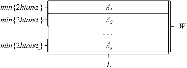
Figure 1: The division of combat area A
The mission reliability of the reconnaissance UAV sub-swarm executing the reconnaissance mission in the combat stage can be referred to in the literature [68]. This study introduces the calculation of the mission reliability of the suicide UAV sub-swarm executing the attack mission.
The relevant indicators of the suicide UAVs are listed in Table 2.

Table 2 indicates that:
The reliability of the attack mission of the suicide sub-swarm includes three aspects: flight reliability, target recognition capability, and target attack capability, as shown in Fig. 2. The calculation of flight reliability and target recognition reliability are the same as that of reconnaissance UAVs [68]. The calculation of target attack ability is related to factors such as attack distance, combat environment, and UAV payload [2]. The target attack capability of the ith suicide UAV can be expressed as depicted in Eq. (2):

Figure 2: The composition of attack mission reliability
where

where
where
As shown in Eq. (3), due to the different positions of enemy targets, the reliability of the attack mission for a single suicide UAV must be calculated point-to-point. Eq. (5) represents the actual attack reliability of a single ith suicide UAV at a flight altitude
where
In particular, to complete the attack mission, the sub-region containing the enemy targets must be assigned suicide UAVs.
The target attack reliability of the suicide UAV swarm for the gth target can be calculated by Eq. (6):
where
Then, Eq. (7) can be applied to calculate the target attack reliability of the entire suicide UAV swarm across the entire operational area, represented by
2.3 The PMS Mission Reliability Modeling and Solution of UAV Swarm
BDD and MOQPSO are used to build the PMS mission reliability model of the UAV swarm. The mission reliability of the reconnaissance UAV sub-swarm and the suicide UAV sub-swarm in the combat stage are obtained from the calculation model in Section 4.1.
2.3.1 Modeling of Mission Reliability Block Diagram for Each Stage of UAV Swarm Combat Mission
For the reconnaissance and attack mission of UAV swarm, the execution process is mainly divided into three stages: launch, flight to the combat area, and combat. The weapon and equipment systems involved in each stage are the launch system, ground station, data link, reconnaissance UAV sub-swarm, and attack UAV sub-swarm. The data link refers to the autonomous communication between UAVs.
Letters a–e are the launch system, ground station, data link, reconnaissance UAV sub-swarm, and attack UAV sub-swarm, respectively; letters A–J is each primary mission; t1, t2, and t3 are the end times of the launch stage, flight to the combat area stage, and combat stage, respectively. The reliability block diagram represents the logical relationship of each system in each stage, which is the basis of reliability analysis. Fig. 3 shows the reliability block diagram of each stage of the UAV swarm’s reconnaissance and attack mission.

Figure 3: Reliability block diagram of the multi-stage mission of reconnaissance and attack UAV swarm
Based on the reliability block diagram, the duration of the launch stage is (0, t1), during which a must complete the launch mission, b requires complete the communication mission, and control missions such as mission programming. Both d and e are in a maneuvering state. All the submissions are connected in a series. The flight duration to the combat area stage is (t1, t2), during which b or c must complete the communication mission, b must complete control missions such as route allocation, and d and e must fly smoothly. Except for the parallel relationship between b and c communication, the other sub-missions are in series connection. The duration of the combat stage is (t2, t3), during which b or c needs to complete the communication mission, b needs to complete control missions such as route allocation, and both d and e must complete their respective missions-reconnaissance for d and attack for e. Except for the parallel relationship between b and c communication, the other sub-missions are in series connection.
2.3.2 BDD Reliability Modeling and Solution for UAV Swarm PMS
The following steps are mainly involved in solving the PMS problem using BDD method: (1) giving the PMS model; (2) constructing fault trees for each mission stage; (3) converting fault trees of each stage into corresponding mission BDDs; (4) simplifying fault trees based on common cause failure to reduce computational complexity; (5) connecting stage BDDs to obtain BDD model for multi-stage missions; (6) simplifying the model based on the primary mission stage to reduce computational complexity, and calculating the results.
(1) PMS model
The UAV swarm has a multi-stage mission
Eq. (9) indicates that when the mission
When executing a multi-stage mission, the same mission can be repeated in multiple stages for the same system. Since each system is non-repairable and the states in each stage are interrelated, i.e., the end state of the previous stage is the initial state of the next adjacent stage, the successful execution of a mission in a system can affect the success of the entire multi-stage mission. Hence, the reliability of the overall mission is not simply equivalent to the product of the reliability of each stage. In particular, Eq. (10) shows that a multi-stage mission’s reliability is equivalent to a single-stage mission’s reliability in the final stage.
(2) Constructing stage fault trees
Based on the reliability block diagram of the UAV swarm reconnaissance and attack mission shown in Fig. 3, the corresponding stage fault tree can be obtained, as depicted in Fig. 4. The series relationships are connected using OR gates, and parallel relationships are connected utilizing AND gates.

Figure 4: Fault trees for multi-stage missions of UAV swarm reconnaissance and attack
(3) Transforming stage fault trees into stage mission BDDs
It is necessary to sort the essential mission variables before the transformation. This study adopts the method of traversing each stage fault tree from top to bottom and from left to right to sort the basic mission variables. Hence, the basic mission order of
Then, the stage mission BDD for each stage can be derived, as illustrated in Fig. 5. When the mission execution begins, all systems will work. When a system fails in a particular stage due to its non-repairable feature. This situation impacts subsequent stages, so defining the system failure duration is necessary. For example, in Fig. 5, the failure of
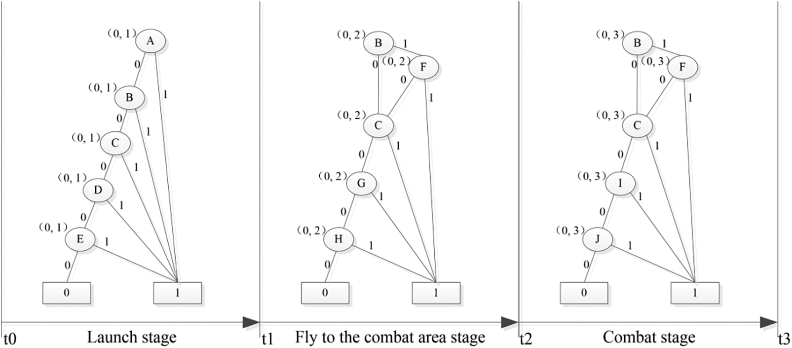
Figure 5: UAV swarm reconnaissance and attack multi-stage mission BDD for each stage of the mission
(4) Connecting stage mission BDDs to obtain the BDD of the overall mission
In a UAV swarm’s multi-stage mission reliability model, there are missions with redundant or parallel structures and common failure essential missions. These structures cause duplicate branches in fault trees, which is part of the mission.
In the process of constructing the BDD of the overall mission, each system follows the rules listed in Table 4 (a detailed explanation of the rules (

1) Completing the primary mission
2) The failed completion of the primary mission
Common failure basic mission. In the multi-stage mission model of UAV swarm combat, if a basic mission in a particular stage
3) It is impossible for the primary mission
4) The successful execution of the basic mission
Based on Eq. (11), the BDD of a certain stage’s successful event
For common failure basic mission
For

Figure 6: Simplified fault tree of
For

Figure 7: Simplified fault tree of
Fig. 8 shows the simplified BDD of the UAV swarm mission. The swarm combat’s mission being successfully executed in stage 1 is represented by the path leading to the zero state endpoint of the mission BDD in stage 1, as shown in Fig. 8’s stage
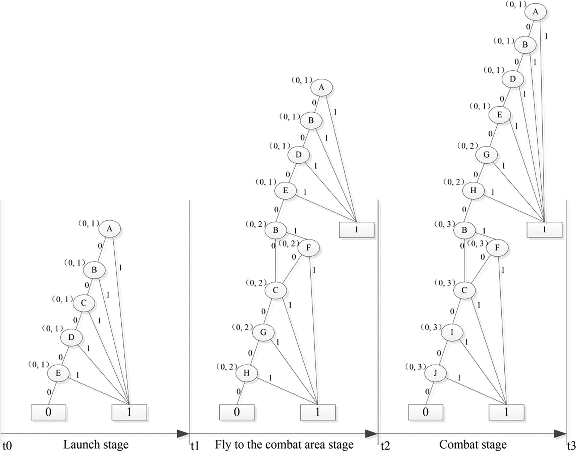
Figure 8: BDD of
(5) Method to simplify the BDD model
Based on the BDD of
Let the status indicator variable of the yth essential mission variable in the platform be:
where
If the basic mission variable
where
Based on the temporal logical relationship of the same event, simplifications can be made to
If
After the above simplification method, the paths no longer have system stage dependencies, and each path is also non-intersecting. The simplified expression of the non-intersecting path sets of BDD for each stage are listed in Table 5.

Since the obtained paths are non-intersecting, the reliability of the stage can be obtained using Eq. (14):
Therefore, the reliability of each stage’s missions can be calculated separately using Eqs. (15)–(17):
By considering the basic mission
where
Finally, the reliability of the UAV swarm reconnaissance and attack mission in each stage
(6) Procedure to calculate BDD
As shown in Fig. 9, the procedures to calculate the BDD are:
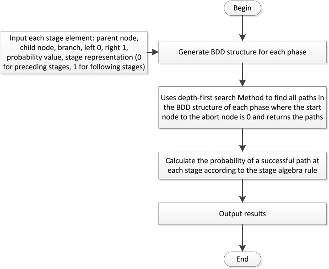
Figure 9: Procedures to calculate BDD
1) Input basic parameters: stage node, edge, and stage information. Node information includes parent node, child node, and branch. Edge information includes edge value (left 0 qnd right 1) and edge probability value. Stage information refers to stage (previous stage as 0, subsequent stage as 1);
2) Use decision tree functions to represent BDD structures for each stage;
3) Use a depth-first algorithm to search for all paths from the starting point (root node) to the termination node (0 node) in each stage and return the paths;
4) Simplify the model based on the four-stage algebraic rules shown in Table 4, and then calculate the probability of successful paths in each stage using Eq. (14);
5) Output the results.
3 The Planning of Operational Test for UAV Swarm
Considering the PMS mission reliability of the UAV swarm, we propose the proposed method of operational test planning. Then, the proposed algorithm, the MOQPSO, is introduced to solve this multi-objective integer optimization problem.
3.1 The Modeling of Operational Test Planning
The cost is another critical factor for the operational test planning of a UAV swarm; thus, the calculation method is provided.
Based on the hypothesis in Section 2.1, the maintenance of launch systems, ground stations, and others is not considered. Thus, when calculating the cost of one plan, the cost of the UAVs is only considered. For UAV swarms taking up reconnaissance and attack missions, the cost of reconnaissance UAV sub-swarms executing the reconnaissance mission in the combat stage can be indicated in the literature [68]. As for the suicide swarm, since recovery is not considered, the cost of the attack mission is calculated as illustrated in Eq. (20):
When planning an operational test, it is necessary to compare the calculated mission reliability with the lower bound of the required mission reliability, Assuming the mission reliability of the reconnaissance sub-swarm is
Then, the operational test planning model is:
The problem of selecting optimal operational plans considering more than one objective (mission reliability and cost) is a multi-objective integer optimization problem. This study uses the multi-objective quantum particle swarm optimization algorithm (MOQPSO) to solve the problem. In this section, the algorithm’s basic process is introduced first and then applied to solve an example.
For integer optimization problems with multi-dimensional inputs, Particle Swarm Optimization (PSO) or its variants can be adopted. However, the traditional PSO method has some disadvantages: (1) it requires many preset parameters, making it challenging to find the optimal parameters; (2) the change in particle positions lacks randomness, making it easy to fall into the trap of local optimization [76]. A good solution is to adopt the Quantum Particle Swarm Optimization (QPSO) algorithm, which increases particle position’s randomness by eliminating particle movement’s direction attribute to remove the correlation between location updates and previous motion of particles [77]. QPSO can also make integer particle positions suitable for addressing the integer optimization issue.
For a multi-objective optimization problem, since objectives can constrain each other, indicating that one objective can improve at the expense of another, achieving optimal performance for all objectives is hard. Hence, a multi-objective optimization problem can only get a set of non-inferior solutions, i.e., the Pareto solution set [78]. Therefore, multi-objective optimization algorithms must be employed to solve this problem. The Multi-Objective Particle Swarm Optimization (MOPSO) algorithm proposed by Cortés et al. [79], in 2003, is a multi-objective optimization algorithm originating from PSO that can only be used for single-objective optimization.
Accordingly, compared to PSO, QPSO improves the calculation method of pbest, MOPSO improves the selection method of gbest according to multi-objective problems. Thus, a multi-objective quantum particle swarm optimization algorithm (MOQPSO) is proposed to combine the strengths above. Referring to the algorithm procedure of QPSO and MOQPSO [80], the algorithm of MOQPSO is shown in Fig. 10.
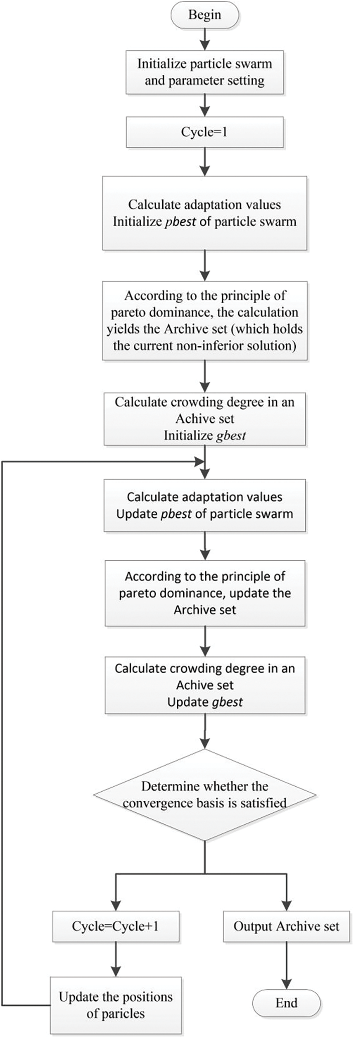
Figure 10: Algorithm of MOQPSO
Based on the flowchart, the algorithm of MOQPSO [80,81] is:
1) Randomly initialize the particle swarm coordinates and some basic parameters, such as population size, archive size, iteration count, weight coefficient, and others.
2) Calculate the fitness value, and use which as the initial pbest of each particle.
3) Determine the Archive set (containing the current non-inferior solutions) based on the Pareto domination principle.
4) Compute the crowding degree in the Archive set, and use it to obtain the initial gbest.
5) Update the particle swarm positions.
6) Define the fitness value and update the particle swarm pbest (when it is unable to distinguish which solution is superior, choose one randomly).
7) Update the Archive based on the Pareto domination principle.
8) Calculate the crowding degree in the Archive set and update the gbest (if the archive exceeds the maximum number of stored particles, it will be pruned using an adaptive grid method).
9) Exit the loop when convergence is met or maximum iteration count is reached; otherwise, proceed to step 4) to continue the loop.
First, the following assumptions are proposed:
1) The UAV swarm performs a reconnaissance and attack mission, where the reconnaissance UAV sub-swarm completes the reconnaissance mission first, and then the suicide UAV sub-swarm completes the attack mission.
2) The length and width of the combat area are 20 and 16 km.
3) The reconnaissance method in the combat zone is shown in Fig. 11, where the UAV reconnaissance sub-swarm flies along the long side of the reconnaissance area from one side to the other, conducting a carpet-style search.
4) The launch site of the UAV swarm is 150 km away from the boundary of the operational area. If the mission reliability of the launch system, ground station, and data link all follow an exponential distribution, their failure rates are listed in Table 6.
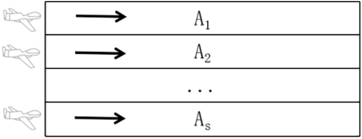
Figure 11: Flight pattern of reconnaissance UAV swarm

The time taken to fly to the operational area can be calculated by Eq. (22). The time spent in the operational area is determined by the sum of the time taken by the reconnaissance UAV swarm to perform reconnaissance missions and the longest attack duration among the suicide UAVs where the time taken by the reconnaissance UAV swarm to perform reconnaissance missions can be determine by Eq. (23), and the longest attack duration among the suicide UAV swarm is assumed to be 3 min.
where
where
The flight speeds of various types of UAVs during different mission stages are listed in Table 7.

4.2 PMS Mission Reliability of One UAV Swarm Plan
The probability of UAV swarm mission failure depends not only on flight reliability but also on the threat level of the operational area, enemy target threats, and the allocation plan of the UAV swarm. Some academic methods have been proposed to solve this problem [82–84], which are not introduced in this study. The calculations of single-stage mission reliabilities are not included in this research to illustrate the effects of the proposed method on operational test planning. The reconnaissance mission reliability of the reconnaissance sub-swarm is assumed to be 0.999, the attack mission reliability of the suicide sub-swarm is 0.998 during the combat stage, and the launch phase of the UAV swarm is 5 min. The flight stage time can be calculated as 45 min, and the operation stage time can be determined as 9 min.
Hence, the simplified reliability of each essential mission variable can be computed as shown in Table 8.

Using the BDD algorithm, the mission reliability of the UAV swarm executing the mission of reconnaissance and attack during the launch phase, flight to the operational area phase, and combat phase can be calculated as 0.9999, 0.9995, and 0.9956, respectively. Based on Eq. (12), the mission reliability of the last stage is equivalent to the overall mission reliability.
Therefore, the reliability of the UAV swarm for reconnaissance and attack missions is 0.9956.
4.3 Operation Test Planning of UAV Swarm
The method introduced in Section 3 will be applied to find optimal plans for the UAV swarm operational test. This study sets the MOQPSO algorithm to iterate 10,000 times and designates a capacity of 50 for the optimal solution set. Then, it gets the total mission reliability and cost for a UAV swarm performing multi-stage reconnaissance and attack missions under different allocation plans and flight altitudes.
Regarding the total cost, the cost of the launch system and ground station are not counted since they can be reused. The cost of the communication link (which refers explicitly to the communication between UAVs) is already included in the cost of UAVs and does not need to be considered separately. Hence, the total cost of the reconnaissance and attack mission for the UAV swarm is the sum of the costs of the reconnaissance sub-swarm and attack sub-swarm.
Two situations can be met in actual military use: enemy target locations are settled or not settled. For both scenarios, the calculation of total mission reliability and cost and the process to get the optimal plans can be conducted.
(1) When Enemy Target’s Locations are Settled
Assuming that the enemy target’s locations are settled, as shown in Table 9.

Fig. 12 shows the final converged Pareto curve (shown by red scatters) of the case using the algorithm we propose. The simulation process requires about 369.77 s. Table 10 lists the first two (ranked by mission reliability) Pareto-optimal plans for the UAV swarm’s reconnaissance and attack mission, along with their total mission reliability and cost.
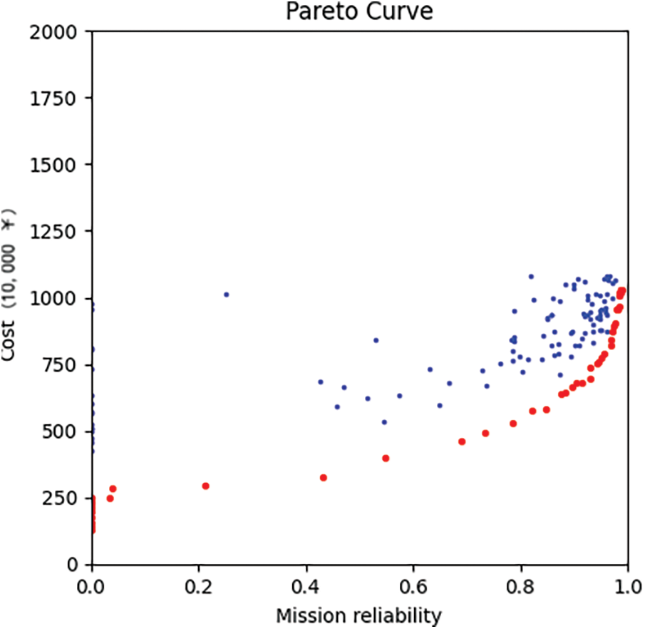
Figure 12: MOQPSO Pareto curve

(2) When Enemy Target’s Locations are Not Settled
Assuming that the location of each enemy target is uncertain, the ranges of distances between the starting point of the UAV swarm and enemies are shown in Table 11.
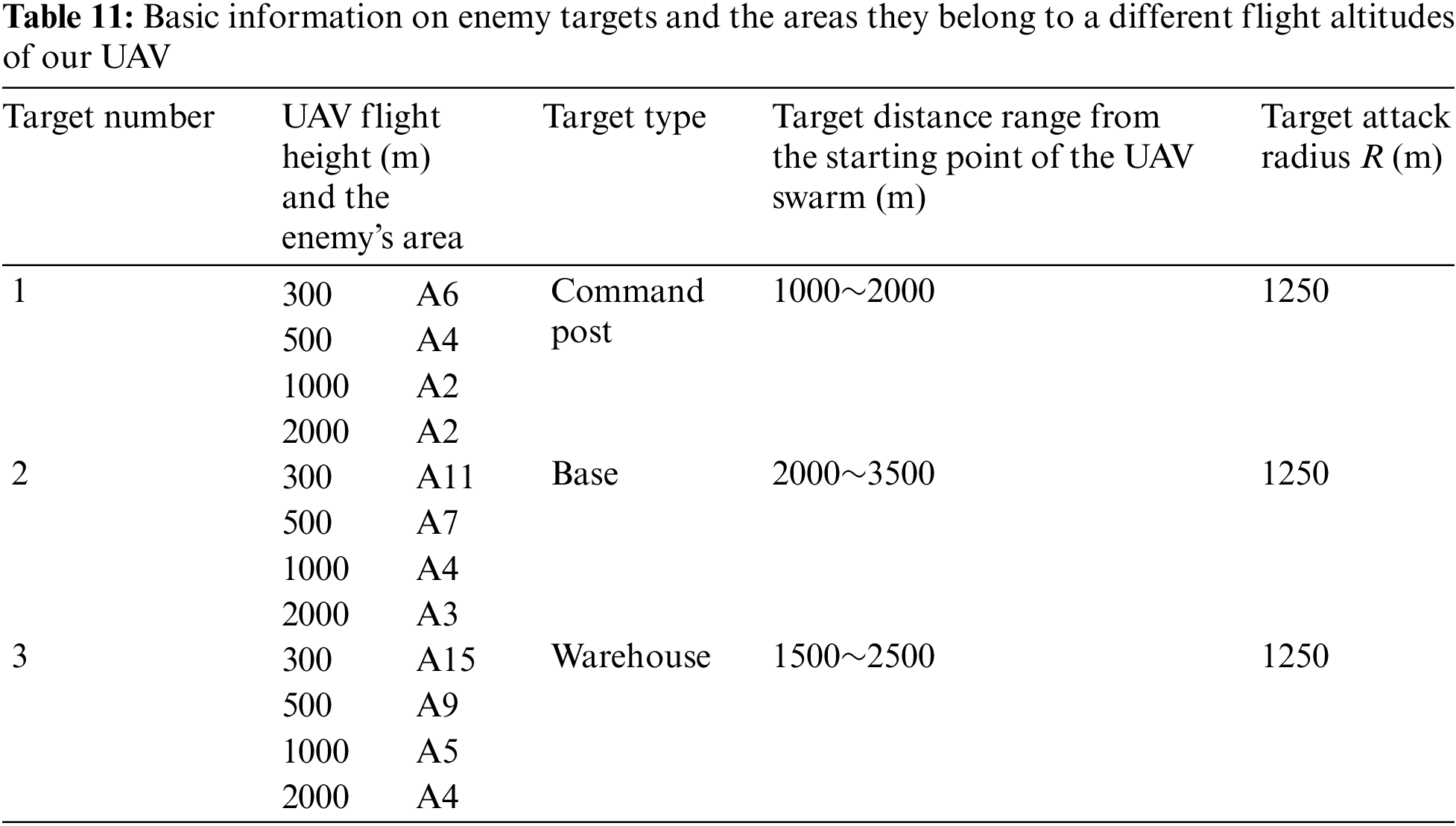
The 100 times simulation results of each preliminary optimal plan are drawn in scatter-plots shown in Figs. 13 and 14, where the vertical axis represents mission reliability, and the horizontal axis represents the number of simulation times. Taking the comparison between Plan 1 and 2 as an example, it is evident that Plan 2 has a more stable and overall better reliability value than Plan 1. Therefore, based on this comparison, Plan 2 is selected.
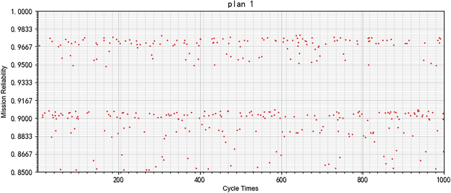
Figure 13: 100 times simulation results of the Pareto optimal plan 1 of the PMS mission
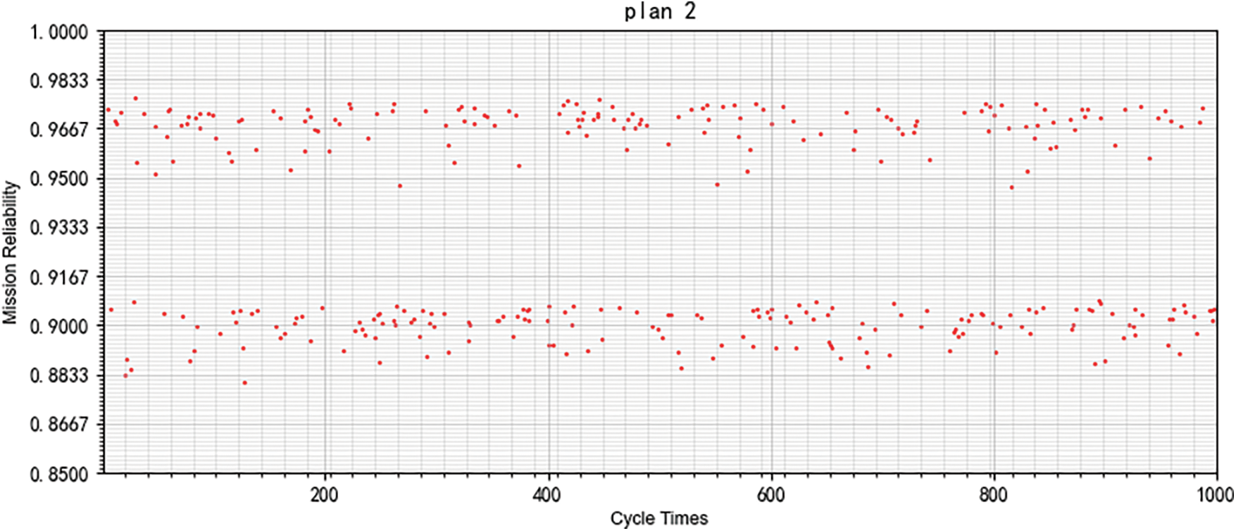
Figure 14: 100 times simulation results of the Pareto optimal plan 2 of the PMS mission
4.4 The Strength of Our Algorithm
This subsection compares the MOQPSO algorithm with NSGA-II [85]. The NSGA-II mentioned is based on a Genetic Algorithm (GA) and is suitable for solving multi-objective optimization problems. Another difference between NSGA-II and classical GA is that NSGA-II has a more efficient selection method for choosing parent and child generations [85]. This study mainly compares the Pareto curve and computational efficiency of MOQPSO and NSGA-II.
Fig. 15 shows the final converged Pareto curve (shown by red scatters) of the case using NSGA-II. The simulation process needs about 772.77 s.
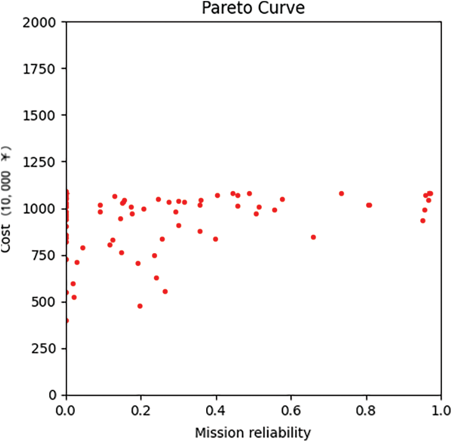
Figure 15: MOQPSO pareto curve
Figs. 12 and 15 indicate that MOQPSO has a better Pareto curve with more centralized optimal particles. In addition, MOQPSO is about 52% quicker than NSGA-II for a few reasons: (1) when updating, MOPSO can preserve the information of relatively good particles while NSGA-II has no memory and changes particles randomly; (2) MOPSO only shares the information of present optimal particles to iterate while NSGA-II shares the information of all the particles, indicating the iteration of the whole generation of uniform; thus, MOPSO can have the chance of iterating faster; (3) compared to NSGA-II, MOQPSO does not have coding, crossover, or a mutation process; it has an easier way of iterating.
Accordingly, the results prove that the proposed MOQPSO performs better when responding to the proposed model.
This study presents a mission reliability-based operational test planning method for UAV swarm. Initially, reliability models using reliability block diagrams, fault trees, and BDD methods are proposed for the multi-stage mission of reconnaissance and attack by UAV swarm. Specifically, in the calculation of mission reliability, the reliability of the combat stage is fully considered by considering factors such as the UAV swarm’s allocation plan, flight altitude, and interceptions by enemies. In addition, based on the proposed multi-stage mission reliability model for UAV swarm, careful consideration of reliability and cost is deemed when using MOQPSO for simulation and selecting Pareto-optimal plans. MOQPSO has good performance in both convergence and efficiency. The proposed method provides a new approach for planning operational test plans for UAV swarms. Future research can be improved in the following aspects: (1) more detailed consideration of the interactions with the enemies; (2) discussion of more mission types; (3) consideration of more area allocation methods; (4) consideration of more flight modes.
Acknowledgement: The authors would like to express their heartfelt gratitude to the editor and the anonymous reviewers for their meticulous evaluation and invaluable feedback on this paper. Their constructive criticism and thoughtful suggestions have greatly enhanced the quality and clarity of this work, contributing significantly to its overall improvement.
Funding Statement: This research is supported by the National Natural Science Foundation of China (with Granted Number 72271239, grant recipient P. J.), Research on the Design Method of Reliability Qualification Test for Complex Equipment Based on Multi-Source Information Fusion. https://www.nsfc.gov.cn/.
Author Contributions: The authors confirm their contribution to the paper as follows: study conception and design: Jingyu Wang; data collection: Jingyu Wang; analysis and interpretation of results: Jingyu Wang; draft manuscript preparation: Jinyu Wang, Ping Jiang, Jianjun Qi. All authors reviewed the results and approved the final version of the manuscript.
Availability of Data and Materials: The input data used in this study’s cases are self-compiled and originate from field research and expert feedback. Besides, given the confidentiality of the subject, the self-compiled data have been appropriately modified from the actual data. We guarantee the authenticity and reliability of the data and have adopted appropriate statistical methods to verify its validity.
Conflicts of Interest: The authors declare that they have no conflicts of interest to report regarding the present study.
References
1. DoD. United States Department of Defense. Unmanned systems integrated roadmap 2017–2042; 2014. Available from: https://ntrl.ntis.gov/NTRL/dashboard/searchResults/titleDetail/AD1059546.xhtml. [Accessed 2023]. [Google Scholar]
2. Li H, Sun HM, Li HQ, HZ W. A review of UAV swarm swarm operations and their early warning detection response strategies. Scuderia Missile. 2018;48(11):46–51 (In Chinese). [Google Scholar]
3. Yang ZY, Wang YL, Lai CL. A study of the current status and trends in the development of UAV swarm warfare. Scuderia Missile. 2019;49(5):34–8 (In Chinese). [Google Scholar]
4. Yu YF, Wang L. New developments in UAV technology. Scuderia Missile. 2019;49(2):34–42 (In Chinese). [Google Scholar]
5. Wang XK, Liu ZH, Cong YR, Li J, Chen H. Overview and future development of small fixed-wing UAV swarms. J Aeronaut. 2020;41(4):15–40 (In Chinese). [Google Scholar]
6. Jia YN, Tian SY, Li Q. A review of progress in UAV swarm research. J Aeronaut. 2020;41(A1):4–14 (In Chinese). [Google Scholar]
7. Waqas A, Kang D, Cha Y. Deep learning-based obstacle-avoiding autonomous UAVs with fiducial marker-based localization for structural health monitoring. Struct Health Monitor. 2024;23(2):971–90. doi:10.1177/14759217231177314. [Google Scholar] [CrossRef]
8. Kang D, Cha YJ. Autonomous UAVs for structural health monitoring using deep learning and an ultrasonic beacon system with geo-tagging. Comput-Aided Civil Infrastruct Eng. 2018;33(10):885–902. doi:10.1111/mice.2018.33.issue-10. [Google Scholar] [CrossRef]
9. Li B. Mission-oriented UAV swarm reliability modeling and assessment (Master Thesis). National University of Defense Technology: Changsha, China; 2018. [Google Scholar]
10. Esary JD, Ziehms H. Reliability analysis of Phased Missions. In: Proceedings of the Conference on Reliability and Fault Tree Analysis; 1975 Sep. p. 213–36. [Google Scholar]
11. Di W, Rui P, Liu DX. Recent advances on reliability of phased mission systems. Singapore: Springer Singapore Pte. Limited; 2019. [Google Scholar]
12. Amari SVA. A practical method for reliability analysis of phased-mission systems. In: Annual Reliability and Maintainability Symposium, 2011; Lake Buena Vista, FL, USA. [Google Scholar]
13. Xie JY. Multi-stage mission system reliability analysis, redundancy configuration optimization and maintenance strategy research (Master Thesis). Chongqing Jiaotong University: Chongqing, China; 2018. [Google Scholar]
14. Xing L, Dugan JB. Analysis of generalized phased-mission system reliability, performance, and sensitivity. IEEE Trans Reliab. 2002;51(2):199–211. doi:10.1109/TR.2002.1011526. [Google Scholar] [CrossRef]
15. Xing LD. Reliability evaluation of phased-mission systems with imperfect fault coverage and common-cause failures. IEEE Trans Reliab. 2007;56(1):58–68. doi:10.1109/TR.2006.890900. [Google Scholar] [CrossRef]
16. Zhai Q, Xing L, Peng R, Yang J. Aggregated combinatorial reliability model for non-repairable parallel phased-mission systems. Reliab Eng Syst Saf. 2018;176:242–50. doi:10.1016/j.ress.2018.04.017. [Google Scholar] [CrossRef]
17. Xing LD. A separable ternary decision diagram based analysis of generalized phased-mission reliability. IEEE Trans Reliab. 2004;53(2):174–84. doi:10.1109/TR.2004.829137. [Google Scholar] [CrossRef]
18. Wang C, Xing L, Tang B. Multivalued decision diagram-based common cause failure analysis in phased-mission systems. Comput Ind Eng. 2020;146:106622. doi:10.1016/j.cie.2020.106622. [Google Scholar] [CrossRef]
19. Mo YC, Xing LD. A multiple-valued decision diagram based method for efficient reliability analysis of non-repairable phased-mission systems. IEEE Trans Reliab. 2014;63(1):320–30. doi:10.1109/TR.2014.2299497. [Google Scholar] [CrossRef]
20. Mo YC, Xing LD, Dugan JB. MDD-based method for efficient analysis on phased-mission systems with multi-mode failures. IEEE Trans Syst, Man, Cybern: Syst. 2014;44(6):757–69. doi:10.1109/TSMC.2013.2277692. [Google Scholar] [CrossRef]
21. Esary. Daniel J, Ziehms H. Reliability analysis of phased missions. In: Reliability and fault tree analysis. Berkeley: University of California; 1975. p. 3–7. [Google Scholar]
22. Zhang T, Guo B, Tan Y, Liu F. A New BDD-based algorithm for reliability analysis of phased-mission systems. J Syst Eng Electron. 2005;27(3):446–8. [Google Scholar]
23. Bian RB, Zhang Y, Pang ZQ, Cheng ZJ, Bai SY. Reliability analysis of multi-stage mission system of escort formation based on binary decision map. J Military Sci Ind. 2020;41(5):1016–24 (In Chinese). [Google Scholar]
24. Yu H, Yang J, Lin J, Zhao Y. Reliability evaluation of non-repairable phased-mission common bus systems with common cause failures. Comput Ind Eng. 2017;111:445–57. doi:10.1016/j.cie.2017.08.002. [Google Scholar] [CrossRef]
25. Wang C, Xing L, Levitin G. Probabilistic common cause failures in phased-mission systems. Reliab Eng Syst Saf. 2015;144:53–60. doi:10.1016/j.ress.2015.07.004. [Google Scholar] [CrossRef]
26. Lu J, Wu X. Reliability evaluation of generalized phased-mission systems with repairable components. Reliab Eng Syst Saf. 2014;121:136–45. doi:10.1016/j.ress.2013.08.005. [Google Scholar] [CrossRef]
27. Chen GY, Zhang XM, Tang XW. Reliability analysis of a generic multi-stage mission system based on separated BDDs. Syst Eng Theor Pract. 2013;33(5):1240–6 (In Chinese). [Google Scholar]
28. Meng L. Binary decision diagram model for reliability analysis of phased mission system. J Natl Univ Defense Technol. 2017;39(2):184–92. [Google Scholar]
29. Yan H, Wang K, Liu ZL, Fu QF. A review of reliability analysis of multi-stage mission systems based on markov methods. J Weapons Equip Eng. 2016;37(6):92–6 (In Chinese). [Google Scholar]
30. Alam M, Al-Saggaf UM. Quantitative reliability evaluation of repairable phased-mission systems using markov approach. IEEE Trans Reliab. 1986;35(5):498–503. doi:10.1109/TR.1986.4335529. [Google Scholar] [CrossRef]
31. Wu X, Yan H, Li L. Numerical method for reliability analysis of phased-mission system using Markov chains. Commun Stat. Theor Methods. 2012;41(21):3960–73. doi:10.1080/03610926.2012.697969. [Google Scholar] [CrossRef]
32. Wu X, Wu X. Extended object-oriented Petri net model for mission reliability simulation of repairable PMS with common cause failures. Reliab Eng Syst Saf. 2015;136:109–19. doi:10.1016/j.ress.2014.11.012. [Google Scholar] [CrossRef]
33. Chew SP, Dunnett SJ, Andrews JD. Phased mission modelling of systems with maintenance-free operating periods using simulated Petri nets. Reliab Eng Syst Saf. 2008;93(7):980–94. doi:10.1016/j.ress.2007.06.001. [Google Scholar] [CrossRef]
34. Ivan M, Bondavalli A. Markov regenerative stochastic petri nets to model and evaluate phased mission systems dependability. IEEE Trans Comput. 2001;50(12):1337–51. doi:10.1109/TC.2001.970572. [Google Scholar] [CrossRef]
35. Volovoi V. Modeling of system reliability Petri nets with aging tokens. Reliab Eng Syst Saf. 2004;84(2):149–61. doi:10.1016/j.ress.2003.10.013. [Google Scholar] [CrossRef]
36. Dugan JB. Automated analysis of phased-mission reliability. IEEE Trans Reliab. 1991;40(1):45–52. doi:10.1109/24.75332. [Google Scholar] [CrossRef]
37. Soman IAK, Ritcey JA, Au SHL. Computationally-efficient phased-mission reliability analysis for systems with variable configurations. IEEE Trans Reliab. 1992;41(4):504–11. doi:10.1109/24.249576. [Google Scholar] [CrossRef]
38. Wang C, Xing L, Peng R, Pan ZS. Competing failure analysis in phased-mission systems with multiple functional dependence groups. Reliab Eng Syst Saf. 2017;164:24–33. doi:10.1016/j.ress.2017.02.006. [Google Scholar] [CrossRef]
39. Li X, Li Y, Huang H. Redundancy allocation problem of phased-mission system with non-exponential components and mixed redundancy strategy. Reliab Eng Syst Saf. 2020;199:106903. doi:10.1016/j.ress.2020.106903. [Google Scholar] [CrossRef]
40. Wu B, Cui L, Fang C. Reliability analysis of semi-Markov systems with restriction on transition times. Reliab Eng Syst Saf. 2019;190:106516. doi:10.1016/j.ress.2019.106516. [Google Scholar] [CrossRef]
41. Deng MT. Regional air defense and anti-missile operations modeling and effectiveness assessment based on OODA ring (Master Thesis). Huazhong University of Science and Technology: Wuhan, China; 2020. [Google Scholar]
42. Wang Y, Sun Q. A three-state faulty Bayesian network for solving combinatorial explosion problems. J Northwest Polytech Univ. 2014;6:857–64. [Google Scholar]
43. Zhou HS, F. LI, Hu B, Huang W. A simulation model for evaluating phased mission system reliability. In: ISECS International Colloquum on Computing, Communication, Control, and Management (CCCM); 2010; Yangzhou, China. [Google Scholar]
44. Remenyte-Prescott R, Andrews JD, Chung PWH. An efficient phased mission reliability analysis for autonomous vehicles. Reliab Eng Syst Saf. 2010;95(3):226–35. doi:10.1016/j.ress.2009.10.002. [Google Scholar] [CrossRef]
45. Steurer M, Morozov A, Janschek K, Neitzke KP. Model-based dependability assessment of phased-mission unmanned aerial vehicles. IFAC-PapersOnLine. 2020;53(2):8915–22. doi:10.1016/j.ifacol.2020.12.1416. [Google Scholar] [CrossRef]
46. Beatriz JOMF, Luiz CSG. Failure analysis methods in unmanned aerial vehicle (UAV) applicaiotns. In: 19th International Congress of Mechanical Engineering; 2007; Brasília, Brazil. [Google Scholar]
47. Andrews JD, Poole J, Chen WH. Fast mission reliability prediction for unmanned aerial vehicles. Reliab Eng Syst Saf. 2013;120:3–9. doi:10.1016/j.ress.2013.03.002. [Google Scholar] [CrossRef]
48. Gonçalves P, Sobral J, Ferreira LA. Unmanned aerial vehicle safety assessment modelling through petri Nets. Reliab Eng Syst Saf. 2017;167:383–93. doi:10.1016/j.ress.2017.06.021. [Google Scholar] [CrossRef]
49. Barbier M, Chanthery E. Autonomous mission management for unmanned aerial vehicles. Aerosp Sci Technol. 2004;8(4):359–68. doi:10.1016/j.ast.2004.01.003. [Google Scholar] [CrossRef]
50. Feng Q, Li Q, Quan W, Pei XM. A review of research on multi-objective particle swarm optimization algorithms. J Eng Sci. 2021;43(6):745–53 (In Chinese). [Google Scholar]
51. Shahabi SN, Manthouri M, Farivar F. A multi-objective ant colony optimization algorithm for community detection in complex networks. J Ambient Intell Humaniz Comput. 2020;11(1):5–21. doi:10.1007/s12652-018-1159-7. [Google Scholar] [CrossRef]
52. Zhang Y, Cheng S, Shi Y, Gong D, Zhao X. Cost-sensitive feature selection using two-archive multi-objective artificial bee colony algorithm. Expert Syst Appl. 2019;137:46–58. doi:10.1016/j.eswa.2019.06.044. [Google Scholar] [CrossRef]
53. Yang C. Research and application of multi-objective optimization algorithms to vehicle path problems with time windows (Master Thesis). Dongguan Institute of Technology: China; 2023. [Google Scholar]
54. Dong MJ, Lin BJ, Liu YC, Zhou LS. Dynamic optimization of navigation satellite laser interplanetary link topology based on multi-objective simulated annealing algorithm. China Laser. 2018;45(7):1–12 (In Chinese). [Google Scholar]
55. Hu ZN, Zhang YW. Genetic algorithm based hybrid techniques for solving multi-objective optimization problems. Electron Design Eng. 2023;31(13):41–5+50 (In Chinese). [Google Scholar]
56. Gu JC, Jiang TH, Zhu HQ. Energy-saving job shop scheduling problem with multi-objective discrete grey wolf optimization algorithm. Comput Integr Manuf Syst. 2021;27(8):2295–306 (In Chinese). [Google Scholar]
57. Huang X, Lu Y, Shen L, Lin B. Solving multi-objective constrained optimization problems based on particle swarm gray wolf hybrid algorithm. Small Microcomput Syst. 2023;44(2):288–99 (In Chinese). [Google Scholar]
58. Gao PC, Wang HY, Song CQ, Cheng CX, Shen S. Multi-objective optimization NSGA family of algorithms and geographic decision making: principles, current status and perspectives. J Earth Inf Sci. 2023;25(1):25–39 (In Chinese). [Google Scholar]
59. Zhu XD, Wang Y, Yang ZL, Guo YJ. A review of typical applications of heuristic multi-objective optimization algorithms in energy and power systems. J Zhengzhou Univ. 2019;40(5):1–11 (In Chinese). [Google Scholar]
60. Zhao HM. Multi-objective optimization algorithm and its application to public bicycle scheduling problems (Master Thesis). Changchun University of Science and Technology: China; 2022. [Google Scholar]
61. Bin H, Zhang LX, Wang SJ, Wang HF. Optimization of rural low-carbon logistics distribution path based on improved multi-objective genetic algorithm. J China Agric Univ. 2023;28(7):224–37 (In Chinese). [Google Scholar]
62. Qiu SM, Wang XK, Du XL, Feng JH, Wang JW. Solving dynamic weapon target allocation problem based on improved multi-objective simplified swarm optimization algorithm. Comput Appl Softw. 2023;40(6):242–9 (In Chinese). [Google Scholar]
63. Qiu SM, Bo CC, Lv YN, Li A. Dynamic weapon target allocation based on multi-objective whale optimization algorithm. J Weapons Equip Eng. 2023;44(2):153–9 (In Chinese). [Google Scholar]
64. Cha YJ, Buyukozturk O. Structural damage detection using modal strain energy and hybrid multi-objectivee optimization. Comput Aided Civ Infrastruct Eng. 2015;30(5):347–58. doi:10.1111/mice.2015.30.issue-5. [Google Scholar] [CrossRef]
65. Cha Y, Agrawal AK, Kim Y, Raich AM. Multi-objective genetic algorithms for cost-effective distributions of actuators and sensors in large structures. Expert Syst Appl. 2012;39(9):7822–33. doi:10.1016/j.eswa.2012.01.070. [Google Scholar] [CrossRef]
66. Yang LN, Cao ZY, Li YX. Study on the composition and operational concept of UAV swarm warfare. Modern Defense Technol. 2020;48(4):44–51 (In Chinese). [Google Scholar]
67. Luo HL, Wu J, Xv QK. Exploring the utilization of UAV swarm operations. Dual-Use Technol Prod. 2020;2020(7):20–3 (In Chinese). [Google Scholar]
68. Wang JY, Jiang P. Allocation strategy for operational test of UAVs based on reconnaissance mission reliability. In: 2023 Global Reliability and Prognostics and Health Management Conference (PHM-Hangzhou); 2023; Hangzhou, China. p. 1–6. [Google Scholar]
69. Yi DWL. Factors affecting UAV flight (six meteorological environments for UAV flight); 2023. Available from: https://mp.weixin.qq.com/s/qRlzUZ71nV5rFxkdmHgfgQ. [Accessed 2023]. [Google Scholar]
70. Zhou SHS. When visibility is poor, don’t “fog” your way in!; 2023. Available from: https://www.xindemarinenews.com/topic/hangyunanquan/2023/0301/46008.html. [Accessed 2023]. [Google Scholar]
71. AQSIQ, SAC. Wind scale; 2012. Available from: https://openstd.samr.gov.cn/bzgk/gb/newGbInfo?hcno=BD0C47493F5ABA08B24176BF8A81218A. [Accessed 2023]. [Google Scholar]
72. Guo JF, Yin ZH, Cui NG. Simulation-based decision-making method for combat effectiveness assessment of air-to-ground missile weapon systems. Control Decis-Mak. 2009;24(10):1576–9 (In Chinese). [Google Scholar]
73. Yue Y. Ground attack UAV operational simulation modeling research (Master Thesis). Nanchang Aviation University: Nanchang, China; 2015. [Google Scholar]
74. Wang N, Du SG. A new approach to BDD sorting for multi-stage mission systems. Sci Technol Eng. 2010;10(17):4217–24 (In Chinese). [Google Scholar]
75. Zhou HS, Li F, Hu B. Reliability analysis of multi-stage mission systems based on binary decision diagrams. J Naval Eng Univ. 2012;24(4):97–100 (In Chinese). [Google Scholar]
76. [Hyperparameter optimization] Quantum particle swarm algorithm (QPSO) python implementation of hyperparameter optimization; 2020. Available from: https://blog.csdn.net/shixin_0125/article/details/104603672. [Accessed 2023]. [Google Scholar]
77. Zheng WB. Study on improvement of particle swarm optimization algorithm and its application (Master Thesis). Qingdao University: Qingdao, China; 2016. [Google Scholar]
78. Algorithms for multi-objective optimization problems and their solution; 2018. Available from: https://blog.csdn.net/paulfeng20171114/article/details/82454310. [Accessed 2023]. [Google Scholar]
79. Cortés N. C., Coello C. N. C. Multiobjective optimization using ideas from the clonal selection principle. In: Genetic and Evolutionary Computation Conference–GECCO 2003; 2003 Jun; Chicago, IL, USA. p. 158–70. [Google Scholar]
80. Sbcypress. MOPSO algorithm learning summary, including OMOPSO, SMPSO, dMOPSO, CMPSO, DDMOPSO, MMOPSO, etc.; 2016. Available from: https://blog.csdn.net/jodie123456/article/details/94874788. [Accessed 2023]. [Google Scholar]
81. (python source code, detailed comments) multi-objective particle swarm optimization algorithm mopso; 2018. Available from: https://blog.csdn.net/m0_38097087/article/details/79818348. [Accessed 2023]. [Google Scholar]
82. Shi HQ, Long YT, Zeng L. IGHS-based model for optimal allocation of air defense fire resources. J Univ Electron Sci Technol. 2021;50(5):720–7 (In Chinese). [Google Scholar]
83. Zhu KX, Chang TQ, Kong DP, Zhang L, Zhang HZ. Modeling of tank position deployment and fire distribution based on swarm algorithm. Syst Eng Electron. 2022;44(2):546–56 (In Chinese). [Google Scholar]
84. Zhou Z, Shen YH. Research on UAV target search, identification, attack combat effectiveness evaluation methods. J Northwest Polytech Univ. 2007;2007(4):608–13 (In Chinese). [Google Scholar]
85. Multi-objective evolutionary algorithm—NSGA-II (python implementation); 2023. Available from: https://blog.csdn.net/qq_41168765/article/details/128053427. [Accessed 2024]. [Google Scholar]
Cite This Article
 Copyright © 2024 The Author(s). Published by Tech Science Press.
This work is licensed under a Creative Commons Attribution 4.0 International License , which permits unrestricted use, distribution, and reproduction in any medium, provided the original work is properly cited.


 Submit a Paper
 Propose a Special lssue
 View Full Text
 Download PDF
 Downloads
 Citation Tools