DOI:10.32604/jnm.2022.019753
| Journal of New Media DOI:10.32604/jnm.2022.019753 | |
| Article |
T01067* Series Fuel Pump Pulp Molded Package Dynamic Drop Simulation
1School of Light Industry and Textile, Qiqihar University, Qiqihar, 161006, China
2Engineering Research Center for Hemp and Product in Cold Region of Ministry of Education, Qiqihar 161006, Heilongjiang, China
*Corresponding Author: H. Zhao. Email: 112179925@qq.com
Received: XX Month 202X; Accepted: XX Month 202X
Abstract: In this paper, combined with the actual situation encountered in the process of product transportation, the finite element analysis software ANSYS/LS-DYNA was used to simulate the dynamic drop process of the buffer packaging structure of T01067* series fuel pump, and the simulation results were analyzed, and a conclusion was drawn. According to the fuel pump weight calculation buffer material thickness, according to the product size and structure design of the pulp molded cushion structure, simulation of static cushioning performance, and dynamic drop simulation, for the subsequent structural optimization cost reduction to provide early warning [1,2]. Check the simulation production cost, reduce many times a large number of experiments and time, structure is ideal type prediction, find out the ideal optimization total, physical test, further optimization and improvement [3].
Keywords: T01067 series; fuel pump; molded pulp; A cushion
(1) As the pulp molding material is using waste paper, so the material force-deformation curve due to the ratio of various paper and its performance is different, there will be a great difference in the numerical value, but the change trend of the material is mostly similar, generally will go through elastic deformation, plastic deformation, fracture failure three stages [4].
(2) The relationship between the rupture strength of molded pulp products and their nominal thickness is determined by using the rupture strength experiment and data analysis software as follows:
When the test materials are waste corrugated paper pulp, Y = 215.8000x+81.4333
When the test materials are all waste newspaper side pulp, Y = 544.8000x−119.2000
(3) Using the side pressure strength experiment and data analysis software, the relationship between the side pressure strength of molded pulp products and their nominal thickness is determined as follows:
When the test materials are waste corrugated paper pulp, Y = 129.2230ex--10.0698
Y = 269.1095ex--42.6650 when all the test materials are scrap newspaper side pulp
(4) Many physical properties of pulp molded liners are related to temperature and humidity. After the treatment of high temperature, high humidity and low temperature, the compressive strength of the molded pulp cushion decreases obviously, on the contrary, the quality of the molded pulp cushion increases due to the hygroscopic effect [5,6].
(5) Determine the size of pulp molded products: 315 * 273 * 59, each technical parameter: thickness of 4 mm, drawing Angle of 3 degrees, round Angle of 6 mm, to prepare for the subsequent establishment of pulp molded packaging liner model by using UG THREE-DIMENSIONAL software [7].
(6) UG software was used to design the pulp molded packing pad of T01067* series fuel pumps. Static compression test was carried out on it, and the simulation results were analyzed to obtain the optimal design scheme [8].
(7) In the drop test to simulate the corner, the simulation model is composed of T01067* series fuel pump, paper-plastic pulp mold liner and rigid ground. Considering all the main factors in the drop process of T01067* series fuel pump, the method of grid division, definition of contact and connection, solution control and so on can be used for other types of fuel pump drop analysis [9].
(8) through the use of virtual simulation technology, the actual drop the whole response of the inconvenience reaction process and the failure mechanism and to obtain more reasonable solution, a small amount of physical experiment to verify the optimized design scheme, is the ideal solution, at the same time, more important is to provide more useful information and basis analysis database.
2 T01067* Series Fuel Pump Pulp Molded Package Dynamic Drop Simulation
The impact problem (also known as the impact) is a special kind of dynamic problem. The most basic characteristics of various impact dynamics problems are as follows: in a very short period of time, the velocity of the impact object changes rapidly after it comes into contact with the structure, and the bearing process of the impact effect is particularly short [10,11].
In ANSYS/LS-NYNA, the following questions should be paid attention to when analyzing various impact processes:
(1) Pay attention to adopting correct material analysis model.
(2) In the impact zone, such as in the real situation, local stress distribution needs to be carried out, and relatively fine mesh needs to be divided. Under the condition that the area is not affected, unit division can be appropriately enlarged [12].
(3) For thin shell units, pay attention to the use of necessary hourglass control in the calculation.
(4) In the large deformation problem, the shell element adaptive meshing technology can be used.
(5) It is suggested to use multiple integral points along the thickness direction of shell element to obtain the stress distribution along the thickness direction of thin shell [13].
(6) Define the correct type of contact algorithm between the surfaces that may be contacted, so as to reflect the actual situation; It is recommended to use automatic contact algorithm to determine problems that may be difficult [14]. The program will automatically detect the contact during calculation, which is suitable for problems with complex contact behavior and process [15].
(7) When the model is created, the rigid body can be selected as the ground material to reduce the calculation time. Even if the rigid body divides a small grid unit, the time will not be increased [16].
2.1 T01067* Series Fuel Pump Pulp Molded Cushion Model Creation
(1) Modeling
When ANSYS software is used for finite element analysis, it will cost a lot of time and energy of engineers to carry out modeling. Although ANSYS software has its own modeling capabilities, it has very limited capabilities and can only deal with relatively simple models. CAD modeling software, such as Catia, Pro/E, UG, Solid Edge, etc., has strong capability of parametric modeling design and can carry out complex Solid modeling [17,18]. If the modeling software is combined with the finite element analysis software to make full use of the modeling software's advantages of rapid and accurate modeling, the modeling function of ANSYS software can be well compensated [19,20]. In this paper, the graphic interface technology between ANSYS software and CAD software is used to highly coupling the interface between UG software and ANSYS software, and the solid model and buffer pad model of T01067* series fuel pump are imported into ANSYS/LS-NYNA, as shown in Fig. 1.
Figure 1: UG model imports the GRAPHICAL interface of ANSYS/Ls-DYNA
When creating the model, pay attention to the determination of the initial unit, which is set as: millinewtons seconds (mmKNs) in this paper.
(2) Model simplification
A certain company only provided the solid picture of T01067x series fuel pump. Since the product body is cylindrical with rounded corners, which is very bad for grid division in finite element analysis, and a single product represents the overall quality of T01067* series fuel pump, UG software was used to simplify the solid picture, as shown in Fig. 2a, and its volume was measured. Quality of T01067* series fuel pumps: maximum 1.09 kg, general 0.77 kg. It can be seen that its density is generally 3.3*10–7 kg/mm3. Similarly, in the finite element analysis of the molded pulp liner, both the drawing Angle and fillet radius of the liner are removed, as shown in Fig. 2b. Since this paper only analyzes the drop of cushion liners for T01067* series fuel pump, the finite element analysis environment and the complete finite element model are presented [21].
Figure 2: Simplification of the model
2.2 T01067* Series Fuel Pump Pulp Molded Cushion Packaging Model Solution
(1) Property parameters and units of materials Table 1:
(2) Grid division
The type, size and shape of mesh affect the accuracy of simulation. In this paper, the T01067* series fuel pump, pulp molded liner and ground are meshes by geometric model meshing method. Among them, T01067 * series fuel pump, paper pulp molding structure liner model can be used free mesh dividing or mapping, determine the grid size of the model by defining the line section number (or segment length) or by ANSYS intelligent judgment: the ground model USES the mapping grid, the grid size by defining the grid number, as shown in Fig. 3.
Figure 3: Mesh generation
(3) Define contact and initial velocity
Contact analysis is an important topic in explicit dynamic analysis. ANSYS/LS-DYNA provides a variety of contact algorithms that can be used to simulate a variety of complex dynamic contact processes. During modeling, contact surfaces and target surfaces are specified at the locations where contact may occur, and then contact is defined, as shown in Fig. 4.
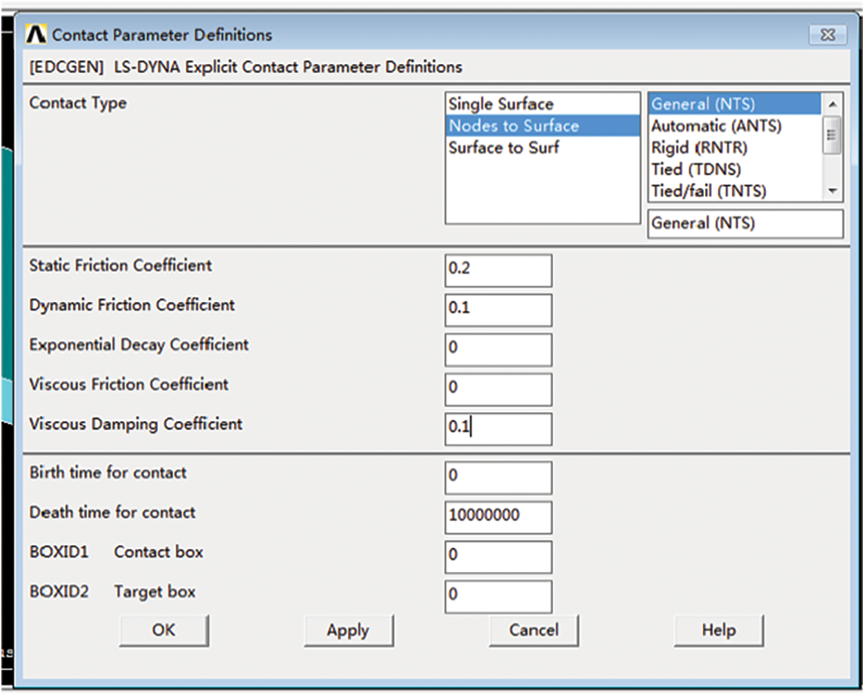
Figure 4: Defines contact types
In transient dynamic problems, it is often necessary to define the initial state of the structural system, such as the initial velocity. According to the free drop formula:
According to the drop test standard, the drop height h is 600 mm. According to the above formula, the velocity V is equal to 108.44 mm/s, and the direction is negative Y-axis. The free-falling posture is the contact between the side of the liner and the ground. The analysis and calculation start from the contact between the liner and the ground.
(4) Model solution and output K file
According to the free drop formula:
The effective time of the drop test simulation is 0.04 s (from the pad contact to the ground), and lS-DYNA mass scaling method is used to speed up the calculation.
During the simulation solution process, a model data file -K, known as the keyword file, will be automatically generated after the solution, which is the input data file of the post-processing LS-DYNA computing program. The file is an ASCII text file that contains node, cell, material, and equation of state information, as well as an analysis of all information issues such as contact, boundary conditions, and load information. In the ANSYS Product Launcher, open this file for solution analysis, as shown in Fig. 5.
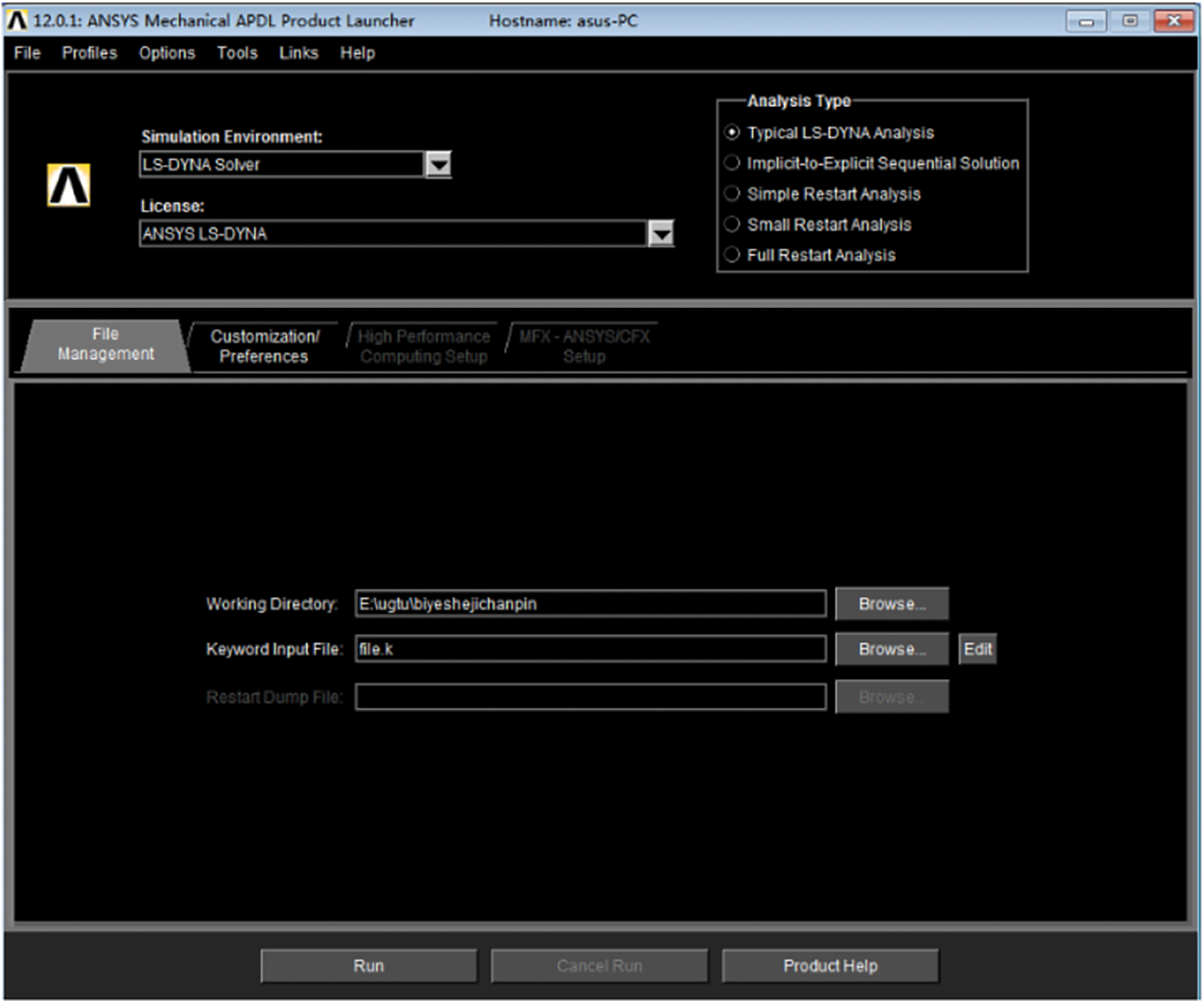
Figure 5: ANSYS solution analysis interface
(5) Results post-processing and analysis
This model takes into account all the main factors in the drop process of T01067* series fuel pump. The method of grid division, definition of contact and connection, solution control and so on can be used for other types of fuel pump drop analysis. According to the post-processing analysis of LS-Prepost software, the following conclusions can be drawn:
First of all, according to the analysis results, the basic parameters, such as elastic modulus and Poisson's ratio, determined according to the pulp molding material test before simulation are correct, and the design method of pulp molding liner summarized in this paper is feasible. See Fig. 6 for the specific simulation results.
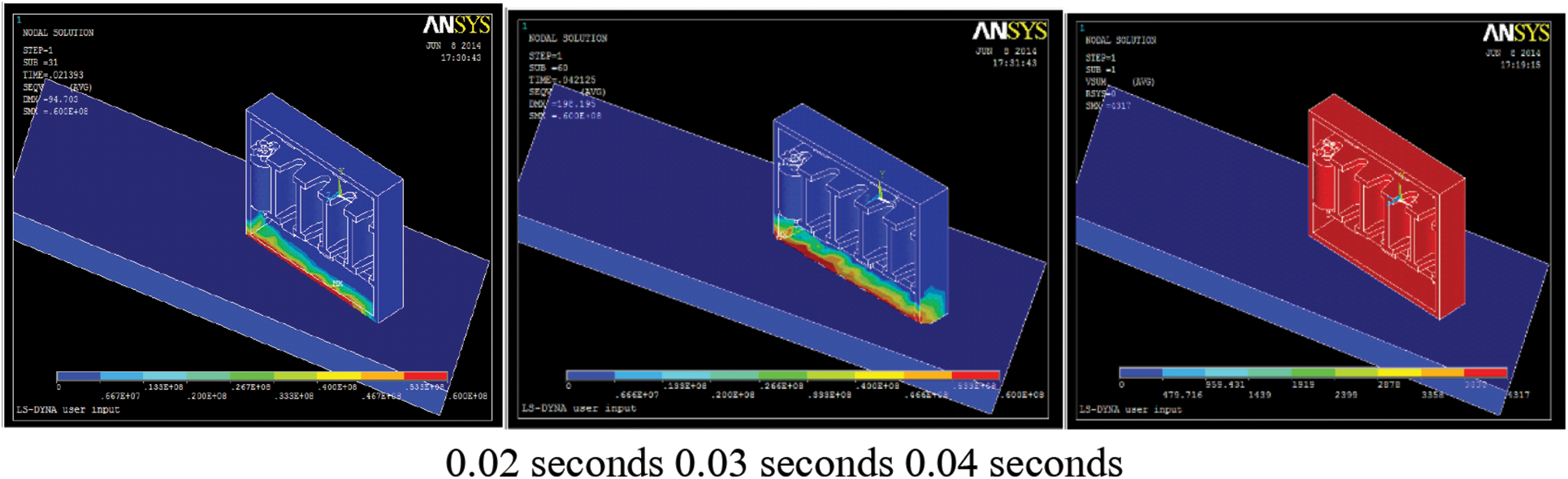
Figure 6: The distribution of von Mises pressure at different moments during the drop of T01067* series fuel pumps
Secondly, based on the actual drop test, I selected several nodes below the fuel pump and plotted the acceleration curve. As shown in Figs. 5 and 6, the maximum acceleration value of the node is about 132 G. Its value is larger than the product's brittle value of 120 G as shown in Fig. 7. The reasons for this phenomenon are as follows: During modeling, the department will be simplified, resulting in a deviation in the results; In the drop test, the outer packing box is not simulated in the model, because the outer packing box in reality is a corrugated box with certain cushioning performance. The paper pulp molded liner has some shortcomings. The above simulation results need to be further verified by experiments [22].
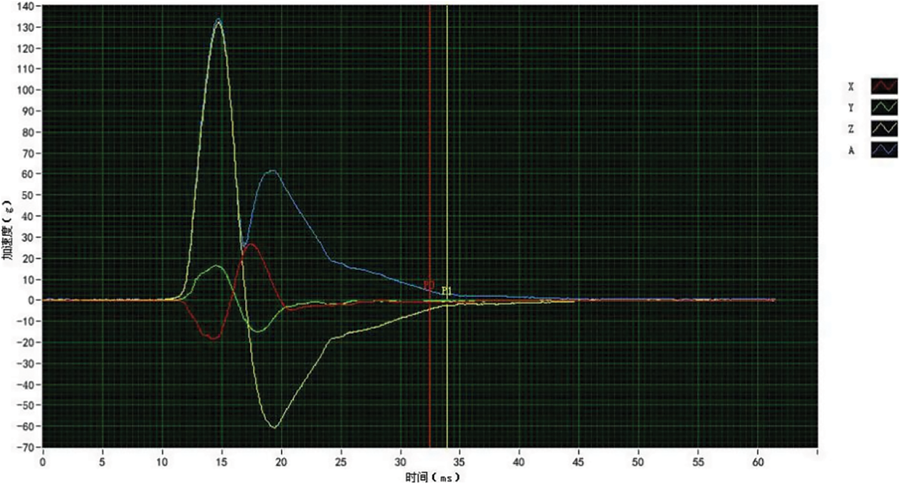
Figure 7: Acceleration curve
In the simulation test in this paper, mass blocks are used instead of T01067* series fuel pump products. The paper pulp molded cushion pad and rigid ground designed in Chapter 3 are used to form ANSYS/LS-DYNA finite element analysis simulation model. Since the liner quality is far less than that of T01067* series fuel pump, the influence of the top liner of T01067* series fuel pump on the simulation results is ignored to simplify the model [23].
The fall height truly reflects the severity of the fall impact environment. The harsher the fall impact environment is, the greater the initial fall velocity is, the more obvious the response of stress, strain and acceleration of the object during the fall, and the more likely the object is to be damaged [24]. According to the acceleration curve, the G value in the dropping process is calculated to determine whether the pulp molded liner meets the requirements of buffering protection during transportation. Therefore, these two parameters are very important in the design of buffering packaging. This echoes the buffer packaging design of the third chapter of pulp molding [25].
The simulation results clearly show the local stress and strain nephogram of the paper pulp molded liners. The stress nephogram of von Mises at different times indicates the force transfer process during the drop process. The impact force of the pulp molding is borne by the liner bottom unit and its side edge unit. More specifically, the pressure on the unit is concentrated on the periphery of the element and both sides of the bottom.
The finite element simulation experiment has short period and low cost, which directly reflects the response process of drop test.
(1) ANSYS/LS-DYNA finite element analysis software was applied to set boundary conditions for the imported model, including mesh generation, load definition, constraint definition and material characteristics definition, etc., so as to establish a real drop environment for the design model.
(2) The post-processing module ANSYS/LS-DYNA was used to solve the problem. The simulation test clearly showed the local stress and strain nebulogram of pulp molded liners. The stress nebulogram of von Mises at different times indicated the force transfer process during the dropping process.
(3) Real drop experiments cannot understand the overall response process and failure mechanism. The use of virtual simulation technology is an ideal solution, which can obtain more reasonable schemes, and a small number of physical experiments to verify the optimized design scheme. Meanwhile, more importantly, it can provide more useful information for the analysis database.
Acknowledgement: The authors thank for the financial supports by Heilongjiang Province Education Department basic business expense scientific research project (135309513, 135409505, 145109502) support; Heilongjiang Province university student innovation and entrepreneurship training program project (201910232115).
Funding Statements: Heilongjiang Province Education Department basic business expense scientific research project (135309513, 135409505, 145109502) support; Chinese university student innovation and entrepreneurship training program project (202110232035).
Conflicts of Interest: The authors declare that we have no conflicts of interest to report regarding the present study.
1. M. Didone, S. Mohanty, J. H. Hattel, M. R. Sonne, E. M. Fiordaliso et al., “On the drying process of molded pulp products: Experiments and numerical modelling,” Drying Technology, vol. 38, no. 12, pp. 1644–1662, 2020. [Google Scholar]
2. H. J. Chen and Y. J. Lu, “Design and simulation analysis of turning over transport device for pulp and molded products,” Journal of Mould Manufacturing, vol. 20, no. 3, pp. 64–68, 2020. [Google Scholar]
3. L. Cen and X. C. Zhang, “Research on strength properties of molded pulp products based on in-pulp additives,” Contemporary Chemical Industry, vol. 49, no. 1, pp. 83–86, 2020. (in Chinese). [Google Scholar]
4. X. Z. Li, B. Wen and B. H. Wang. “Structural Design of Hot Water Pulp Molding and CNC Machining of Mold,” Journal of wuhan university of light industry, vol. 38, no. 6, pp. 96–101, 2019. [Google Scholar]
5. Z. Tian, S. L. Xiao and Q. L. Wang, “Effects of temperature, humidity and ultraviolet aging on the properties of molded pulp materials,” Packaging Engineering, vol. 40, no. 17, pp. 96–103, 2019. [Google Scholar]
6. L. Cen and X. C. Zhang, “Preparation and characterization of anti-chip pulp molded samples,” Cellulose Science and Technology, vol. 27, no. 3, pp. 45–50, 2019. [Google Scholar]
7. F. L. Li. “Research on household products design based on pulp molding process --comment on practical technology of pulp molding production,” China Paper, vol. 38, no. 6, pp. 91–92, 2019. [Google Scholar]
8. G. Q. Chen, D. H. Wu, J. D. Wang, D. L. Wu and Z. J. Fan, “Design of control system for pulp moulding transfer equipment,” Machine Tool & Hydraulics, vol. 47, no. 8, pp. 169–172, 2019. [Google Scholar]
9. W. J. Lin, “Optimization and improvement analysis of hot press setting device for pulp molded products,” Electromechanical Engineering Technology, vol. 40, no. S1, pp. 17–19, 2021. [Google Scholar]
10. Q. Z. Liu, Z. G. Shen, L. Huang, Z. H. Yu and G. G. Chen, “Research status and development trend of molded pulp products,” Packaging Engineering, vol. 39, no. 7, pp. 97–103, 2008. [Google Scholar]
11. J. Q. Ma, K. M. Mao, Z. X. Lin, Y. Qiu, “Experimental study on the shrinkage rate of pulp molding considering geometrical features,” Packaging Engineering, vol. 40, no. 3, pp. 61–71, 2019. [Google Scholar]
12. J. X. Wei and X. C. Zhang, “Research on screen printing technology of molded pulp packaging products,” Light Industry Machinery, vol. 35, no. 3, pp. 60–64, 2017. [Google Scholar]
13. W. W. Zhang, J. Yu, L. J. Zhang, Y. M. Fan, “Preparation and Properties of Nanocellulose/Filter Pulp Composite Microfiltration Membrane,” Forestry Science, vol. 56, no. 9, pp. 112–118, 2020. [Google Scholar]
14. D. Q. Sun, S. Wei, B. Li, X. An, H. M. Liu, J. Hao, “Simulation analysis of projector transportation packaging based on Ansys Workbench,” Packaging engineering, vol. 40, no. 9, pp. 11–16, 2021. [Google Scholar]
15. Y. Xu, Y. T. Zhang, Z. Q. Fu, L. Zhang, C. H. Zhou, “Difference analysis of container static pressure and drop test results with different contents,” Packaging Engineering, vol. 40, no. 15, pp. 62–66, 2019. [Google Scholar]
16. P. C. Luan, J. Li, S. M. He, Y. S. Kuang, L. H. Mo, T. Song, “Investigation of deposit problem during sugarcane bagasse pulp molded tableware production,” Journal of Cleaner Production, vol. 237, no. 23, pp. 83–91, 2019. [Google Scholar]
17. K. P. Martínez, R. Morabito and E. A. V. Toso. “A coupled process configuration, lot-sizing and scheduling model for production planning in the molded pulp industry,” International Journal of Production Economics, vol. 204, pp. 227–243, 2018. [Google Scholar]
18. Y. Kajihara, Y. Tamura, K. Matsuzaka, S. Kadoya and F. Kimura, “Measuring the moisture content of pulp injection molded products with terahertz waves,” International Journal of Automation Technology, vol. 11, no. 5, pp. 766–771, 2017. [Google Scholar]
19. M. Didone, P. Saxena, E. Brilhuis-Meijer, G. Tosello, G. Bissacco et al., “Moulded pulp manufacturing: Overview and prospects for the process technology,” Packaging Technology and Science, vol. 30, no. 6, pp. 231–249, 2017. [Google Scholar]
20. Y. S. Aguerre and G. B. Gavazzo, “Lignocellulosic recycled materials to design molded products: Optimization of physical and mechanical properties,” Journal of Materials Science and Engineering A, vol. 4, no. 6, pp. 222–231, 2016. [Google Scholar]
21. K. P. Martínez, E. A. V. Toso and R. Morabito, “Production planning in the molded pulp packaging industry,” Computers & Industrial Engineering, vol. 98, pp. 554–566, 2016. [Google Scholar]
22. H. B. Zhang, Z. Y. Zhao, H. Sun, L. Q. Wang, Y. Qian et al., “Effects of modified dispersed rosin gum on the apparent properties of paper molded products,” Packaging Engineering, vol. 37, no. 15, pp. 78–83, 2016. [Google Scholar]
23. F. S. Wu, Z. M. Wang, Z. Y. Tang, “Research on Molding Technology of Refined Industrial Packaging Pulp Molded Products,” South China University of Technology, 2016. [Google Scholar]
24. Y. D. Li, “Research on crash simulation test of wheelchair based on ANSYS/LS-DYNA,” Machinery Manufacturing and Automation, vol. 49, no. 5, pp. 106–108, 2020. [Google Scholar]
25. Z. H. Chen, Y. F. Nie, “Drop analysis of transport container based on ANSYS/LS-DYNA,” Packaging and Food MachinerySpecter, vol. 34, no. 6, pp. 35–38, 2016. [Google Scholar]
 | This work is licensed under a Creative Commons Attribution 4.0 International License, which permits unrestricted use, distribution, and reproduction in any medium, provided the original work is properly cited. |