DOI:10.32604/cmc.2020.012437
| Computers, Materials & Continua DOI:10.32604/cmc.2020.012437 | |
| Article |
Design of Authoring Tool for Static and Dynamic Projection Mapping
1Seoul National University of Science and Technology, 172 Gongneung-dong, Nowon-gu, Seoul, Korea
2Hoseo University 165 Sechul-ri, Baebang-eup, Asan-si, Chungcheongnam-do, Korea
3Soonchunhyang University, 336-745, Asan-si, Chungcheongnam-do, Korea
4Seoul Media Institute Technology, 661 Deungchon-dong, Gangseo-gu, Seoul, Korea
*Corresponding Author: Yoo-Joo Choi. Email: yjchoi@smit.ac.kr
Received: 30 June 2020; Accepted: 22 August 2020
Abstract: This study introduces the design details of a tool to create interactive projection-mapping content in a convenient manner. For the proposed tool design, a homography-based camera–projector calibration method was applied with the use of red–green–blue-depth images from a Kinect V2 sensor that did not require accurate camera calibration prerequisites. In addition, the proposed tool simultaneously achieved static projection mapping that projected the image content onto a fixed object, and dynamic projection mapping that projected the image content onto a user’s body, by tracing the moving user. To verify the effectiveness of the proposed content-creation tool, users with no programming capabilities were employed to create contents that were projected onto various objects in fixed positions and a user’s body in various poses, thereby analyzing the tool’s completeness. Moreover, the projection accuracy was analyzed at different depth positions, and the projection-mapping accuracy was verified with the use of the proposed method.
Keywords: Dynamic projection mapping; camera–projector calibration; Kinect projection mapping; content authoring tool
The evolution of augmented reality (AR) technology has led to its widespread use in various fields, e.g., medicine, industry, education, mobile games, and entertainment [1–3]. AR employs a computer graphic technique that uses an integrated display that matches an object in the real world to a different object in a virtual world [4]. There are multiple AR variants. For example, one variant may show the augmented information on a monitor or a smartphone. Another variant may display the augmented information via a head-mounted display (HMD) or glasses [5,6]. These AR variants have disadvantages. First of all, they only allow a single user to experience a virtual world. Second, they restrict the space within which the user can move and motion owing to the device. Third, they easily cause diminished concentration, nausea, or dizziness.
Therefore, interest in spatial augmented reality (SAR) has been increasing. SAR is a projection-mapping technique that enables multiple users to experience virtual content simultaneously, without the need to wear specific gear. SAR enhances visual information by projecting images onto the surfaces of real three-dimensional (3D) objects and spaces [7]. The projection-mapping technique is extensively applied in the field of media arts to show colorful displays, e.g., advertisements, exhibitions, and performances. Moreover, dynamic projection mapping that traces and projects onto a moving object, has been highlighted extensively compared with the static version that is projected onto a still object [8–11].
However, creating the dynamic projection-mapping content can be challenging, as explained below. First, a time-consuming calibration is required between the projector and the sensor (e.g., a camera) used for tracking moving objects. In addition, an accurate camera calibration must be conducted before the camera-projector calibration. Second, the calibration error may increase as the distance between the projector and the camera used for tracking increases. Third, unlike the static projection-mapping content, which can be easily created by a user, dynamic projection-mapping content requires a complicated programming process because there are no commercialized content-creation tools. Owing to these problems, it is difficult for media producers and artists who have little knowledge of programming to create dynamic projection-mapping contents without any other assistance.
As such, this study proposes an authoring tool that can dynamically project the desired image contents onto a body by tracking the user’s skeleton information without the use of any complicated programming process. The proposed tool employs a homography-based camera–projector calibration method that uses depth information but does not require accurate camera calibration. In addition, it uses text-based configuration files to allow nontechnical users to create projection-mapping content without any other assistance. The tool executes static and dynamic projection mappings.
To verify the effectiveness of the proposed content-creation tool, users with no programming experience were employed. These users were asked to create a static projection-mapping content for mapping onto a fixed object, and dynamic projection mapping content for mapping onto the body of a moving user within a specified amount of time. In addition, the projection-mapping accuracy was analyzed comparatively based on users in motion at different depth levels. The proposed tool is expected to be extensively applied in stage art fields that require various stage effects, and in public relations.
The rest of this study is organized as follows. Section 2 analyzes the projection mapping process, the camera–projector calibration, and the current related methods. Further, it investigates the characteristics of commercial projection-mapping software. Section 3 describes the design details of the proposed tool. Section 4 provides the details of the experimental implementation and presents the experimental results. Section 5 discusses the limitations and future work of the proposed tool, and outlines the conclusions.
2.1 Classification of Projection-Mapping Techniques
Projection-mapping methods are classified into static and dynamic. Static projection mapping implies that the shape or position of the target object is fixed. In static projection mapping, if the target object moves, the projection direction must be manually adjusted. This mapping is applied in façade work [12] that performs projection mappings in large buildings, merchandise advertisements [13], and media arts [14].
Dynamic projection mapping is when the position or shape of a projection target object varies. The method traces the position or shape of a target object with various sensors, and maps the virtual content to the real content according to the traced information. The target object may include a dynamically moving cloth, the human body, a face, or a general object. It is more difficult to implement dynamic than static projection mapping. Additionally, a complicated calibration process is required in advance. However, it can increase the audiences’ interest and immersion.
Siegl et al. [15] presented a method that traces a white-colored object (the statue of Agrippa) with an RGB-D camera, and generated projection maps onto the object from different angles. Zhou et al. [16] presented a method that traced and mapped a real object with projection mapping on a movable object system (Pmomo), which was based on the Kinect V2 RGB-D camera. Narita et al. proposed a technique that traced the motions of a deformable invisible marker, which was printed by infrared (IR) ink with the use of a high-speed projector and camera. The same authors also analyzed a T-shirt’s motion with the use of an invisible marker which was attached to it. They projected appropriately the deformed image content onto the image of the T-shirt according to the analyzed information [8].
Lee et al. [9] presented a mapping method that projected maps onto the costume of an actor who moved in real time. This method constructed a mask based on the actor’s regional information to select a two-dimensional (2D) video, and applied this to the projection. Existing projection-mapping techniques use high-priced equipment, or applied simple 2D masks which are constructed by extracting the area occupied by the user from a camera image. Three-dimensional (3D) spatial information was not utilized in this case.
2.2 Camera–Projector Calibration
Acquiring a picture of an actual 3D space with a camera produces a 2D image. This 2D image determines the position and direction of the camera according to the camera’s characteristics. Herein, the intrinsic camera parameters refer to parameters that define the characteristics of the camera itself. Extrinsic camera parameters refer to the parameters that correspond to the camera’s position and direction. To predict how the points in 3D space are projected onto 2D camera images, and to inversely restore the 3D coordinates of the observed point from the 2D camera images, the conversion relationship, composed of the intrinsic and extrinsic camera parameters, must be determined. The process used to identify the intrinsic and extrinsic camera parameters is referred to as the camera calibration process.
Various methods have been presented to calculate the camera’s intrinsic and extrinsic parameters. Abdel-Aziz et al. [17] proposed the direct linear transformation (DLT) that defines the conversion between the 3D world and 2D camera coordinates. Zhang [18] presented a method that extracts n extrinsic and intrinsic calibration parameters from n poses based on a method that uses feature points in conjunction with three poses or more.
A projector is needed to display AR in a large-scale facility. However, a balance between practicality and accuracy is necessary to precisely adjust a projector with a long focal distance. Projector calibration determines the projector’s intrinsic and extrinsic parameters in a manner similar to the camera calibration process. Similar to the case of a camera, the projector’s intrinsic parameters indicate its focal length, image center, and lens deformation status, and the extrinsic parameters indicate the projector’s position and direction.
Currently, there are two projector–calibration methods, namely, pin-hole model-based calibration [19,20] and homography-based camera–projector calibration [21,22]. The pin-hole-model–based calibration method considers a projector as an inverse camera and performs projector calibration by applying the Zhang’s camera calibration method [18]. As shown in Fig. 1, the calibration of the camera is performed using a printed calibration board. In other words, a conversion matrix is obtained. Another calibration board is projected by a projector and the projected calibration board is photographed with a camera. Subsequently, the 3D spatial coordinates of the projected calibration board are estimated with a conversion matrix (H, in Fig. 1). The projector’s intrinsic and extrinsic parameters are determined based on the estimated 3D spatial coordinates and the projection-screen coordinates.
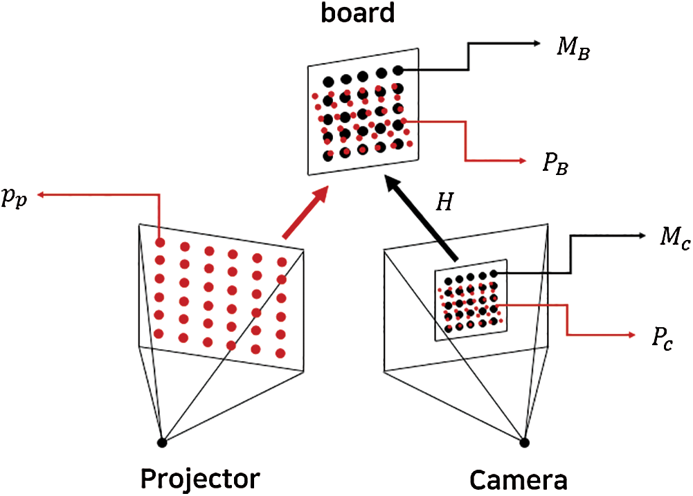
Figure 1: Pin-hole model-based camera–projector calibration model
The homography calibration method projects a calibration board onto a screen, a wall surface, or a white board with a projector. The projected image is obtained again with a camera and is saved as a 2D image. The calibration is performed after the determination of the homography relationship between the saved camera image and the projected image.
The camera–projector calibration method based on the pin-hole model requires an accurate camera calibration in advance. Conversely, homography calibration encounters difficulties in achieving accurate projections onto objects that are positioned at various depths. Therefore, this study applied the homography calibration approach which does not require accurate camera calibration, and devised a method that can a) perform appropriate projection mapping by extracting homographies at various depth values and b) selectively apply the homography according to the depth value of the target object.
3.1 Overview of the Proposed Tool
The projection mapping content authoring tool proposed in this study enables both static projection mapping onto a fixed object and dynamic projection mapping onto a moving person based on tracking without the need of any programming processes. It builds on the simple video mapping tool (SVMT) [23] that supports only static projection mapping and implements human body tracking-based dynamic projection mapping. Fig. 2 shows the four modules of the proposed tool. The first module, the content configuration reading module, reads a content configuration file saved in a text form to load video clips or image files required for projection mapping, and generates polygonal mesh frames according to the frame properties defined in the file. The texture property of polygonal mesh frames defines and renders video clips and image files for projection mapping, and maps them onto the initial positions of the polygonal mesh frames. It also lets the user manually assign the positions and detailed shapes of the polygonal mesh frames. The second module, the camera–projector calibration module, computes and saves the homography between camera–projectors with different camera depth locations. The third module performs static projection mapping. It renders polygonal mesh frames to specific positions according to the properties defined in the content configuration file and the manual adjustments made by the user. The fourth module tracks a moving user and projects the desired media contents onto the human body. It tracks user movements with the Kinect V2 system that traces 25 human body joints, and computes and renders the positions of the polygonal mesh frames that match the user’s body with the homography computed in the camera–projector calibration module. The next section provides elaborate details on the module.
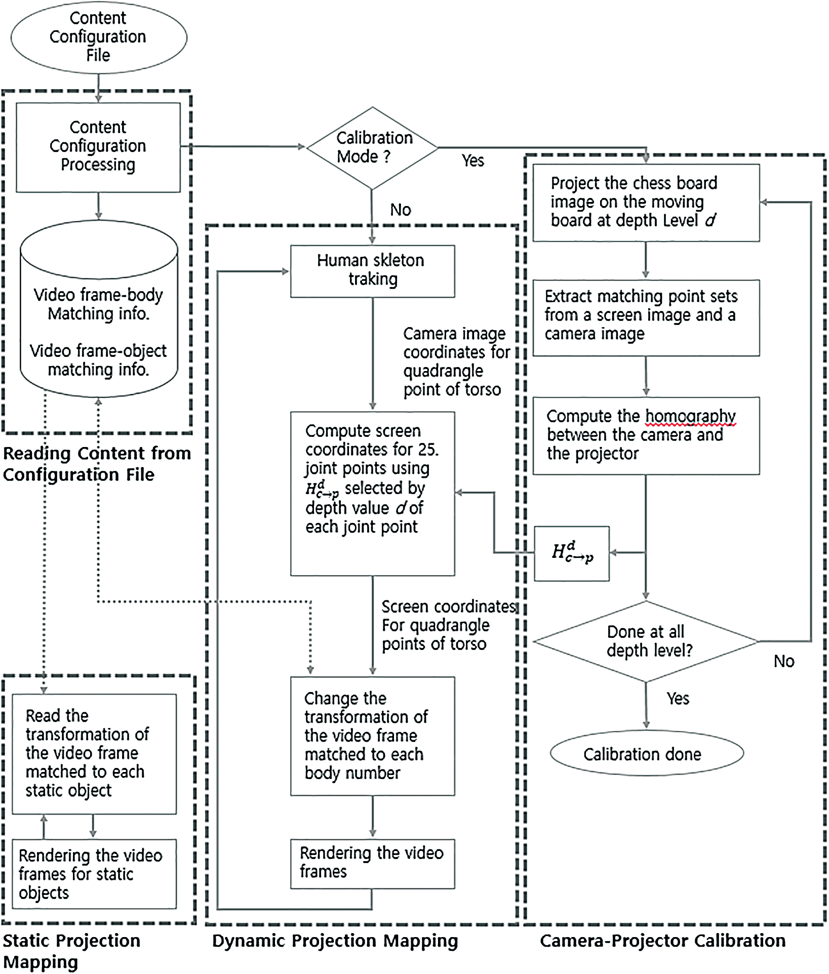
Figure 2: Schematic overview of the proposed tool
3.2 Content Initialization Based on Content Configuration File
The properties of the polygonal mesh frames used for projection mapping and the media files (video clip and image file) used for mesh frame texture were defined in a content configuration file. They have the same configuration as SVMT [23] with two differences: 1) the six frames (Frame 1 to Frame 6) are designated exclusively for dynamic projection mapping, and 2) the frame that matches a fixed object starts from Frame 7. As a result, it can simultaneously track six human bodies and perform dynamic projection mapping. The initial position of each frame is set to predefined values. A user defines video clips and image files for a desired projection mapping content and selects the number of frames. For each frame, video and image numbers are assigned for mapping. These configurations are saved in a content configuration file according to which the proposed tool loads the video and image files, and generates polygonal mesh frames that are rendered onto the monitor. Using the mouse, each frame is moved to a desired position and the shape of the polygonal mesh frames are manually adjusted to match the shape of the target object for projection.
3.3 Homography-Based Camera–Projector Calibration Module
The calibration module projects the chessboard image on a board arranged at regular intervals to calibrate the camera and projector. The camera is then used to capture the projected image and identify the match between the captured image and the display screen image, as shown in Fig. 3. It stores the camera image coordinates, depth coordinates, and the screen image coordinates for each point on the chessboard.
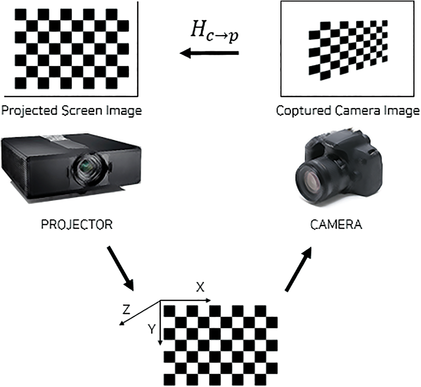
Figure 3: Homography between the captured camera and the display images
Eq. (1) represents the homography between the captured camera image and the projected screen image.
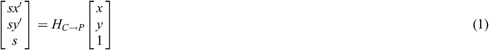
where [x, y] and [x’, y’] denote the pixel coordinates of the captured camera image and the matched screen image, respectively. Fig. 3 shows the display screen image and projected chessboard on the moving white board. We manually adjusted four vertices of the chessboard on the screen image and projected the deformed chessboard onto the moving white board. After the white board was moved, we manually re-adjusted the vertices of the chessboard on the screen image and projected it again. The projected chessboard was captured with the use of the camera. Fig. 4 shows a white board at the same orthogonal distance from the camera. Fig. 4a shows the chessboard projected by placing the whiteboard on the right and Fig. 4b shows the chessboard projected by placing the whiteboard on the left.
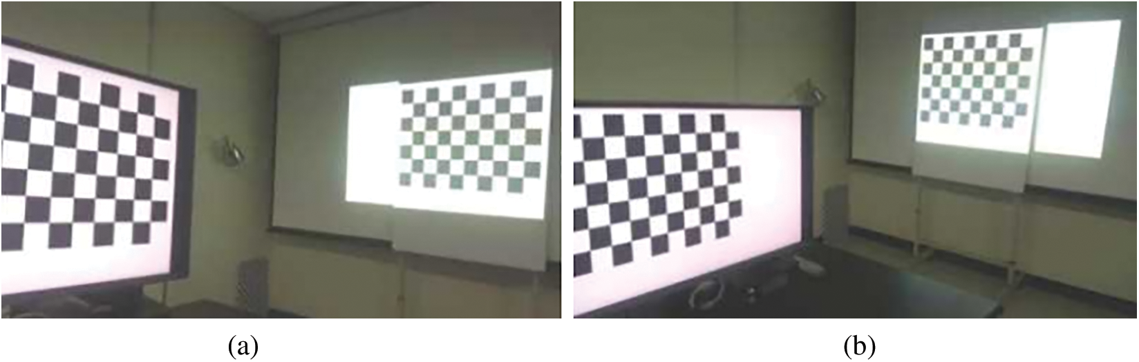
Figure 4: Projection of a chessboard on a moving board
To calculate 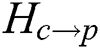 , the screen image coordinates [sx’, sy’] and the camera image coordinates [x, y] of 54 corner points of the chessboard were automatically extracted in each of the poses of the chessboard. The screen image coordinates of the 54 corner points were defined based on four rectangular vertices (V0, V1, V2, V3) of a 9 × 6 chessboard, as shown in Fig. 5.
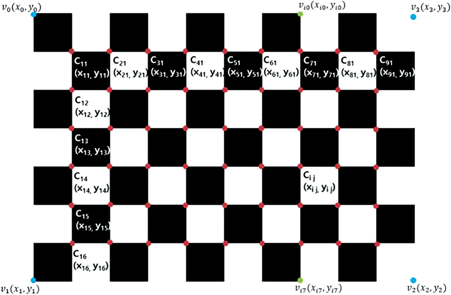
Figure 5: Screen coordinates of the 54 corner points (red) and the four vertices (blue) of a 9 × 6 chessboard
Eq. (2) describes how to calculate the screen coordinates [ ,
,  ] of the corner point (
 ) of the chessboard.

where  ,
, 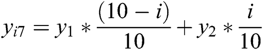 .
.
The camera coordinates (x, y) of the corner points are extracted using the findChessboardCorners() function of the OpenCV library. Fig. 6 shows the automatically detected chessboard corner points in the Kinect V2 color camera image. With the use of the detected camera coordinates of each corner point, the homography 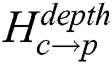 can be defined according to the depth level. The camera image coordinates and depth coordinates of the corner points, and the homography for each level are saved in the calibration file. Fig. 7 shows the different positions of the board corresponding to three depth levels and the homographies at each depth.
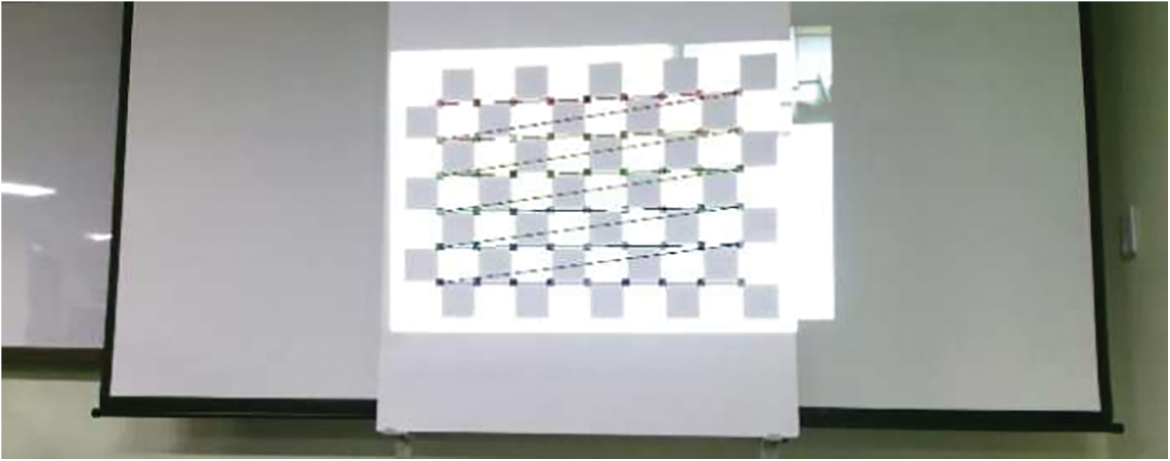
Figure 6: Fifty-six corner points of the chessboard automatically extracted from the image using the OpenCV library
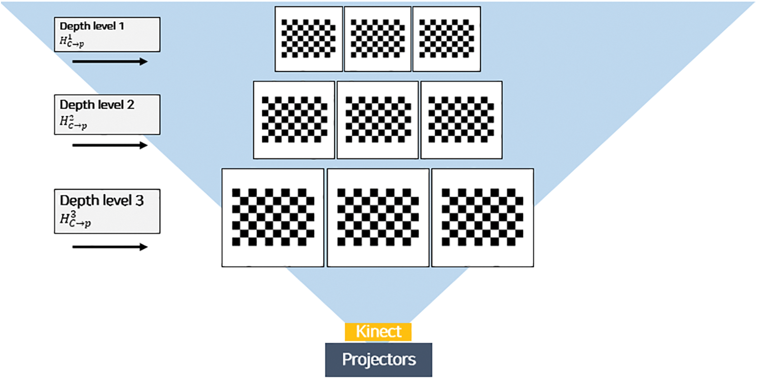
Figure 7: Homography according to the position of the chessboard placed in different three-dimensional (3D) spaces
3.4 Dynamic Projection Mapping According to Human Movement
The dynamic mapping module is intended for the mapping of a video or an image onto the body of the user. It first checks to ascertain if there is a homography that corresponds to the depth level of the corner point stored in the calibration module. If there is no saved homography information, the dynamic mapping module does not work. If there is information, the average depth values of the corner points are obtained at each depth level. The average depth values of the corner points are used to select the proper homography for the joint points. To correctly map each joint tracked in Kinect, the joint coordinates and joint depth information need to be known. Kinect uses infrared sensors to track joints. Thus, the coordinates of the joints are aligned to the frame of the infrared sensor. Thus, the depth sensors, such as the infrared sensor resolution, can obtain the depth information without any additional work. However, corner point coordinates and the homography used in this study were calculated in response to the resolution of the color camera. Therefore, to use joint coordinates, joint coordinates corresponding to color image resolution should be identified. To achieve this, we used a utility called coordinate mapper to obtain the color image coordinates that corresponded to the joint coordinates of the infrared sensor. Additionally, as shown in Fig. 8, the homography for each joint is selected from the set {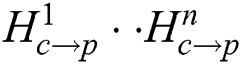 } by comparing the average depth value of the corner points with the depth value of the joint. Furthermore, by identifying the nearest depth level from each joint point. The screen coordinates of the joint are calculated with Eq. (1). In the proposed system, the calculated screen coordinates of the left/right shoulder and the left/right pelvis are set to the coordinates of the four corner points of the video or image specified in the configuration file, as shown in Fig. 9.
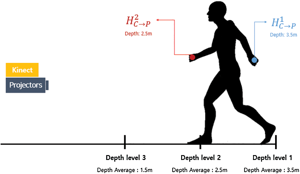
Figure 8: Selected homography based on the estimation of the depth level that corresponds to the joint depth
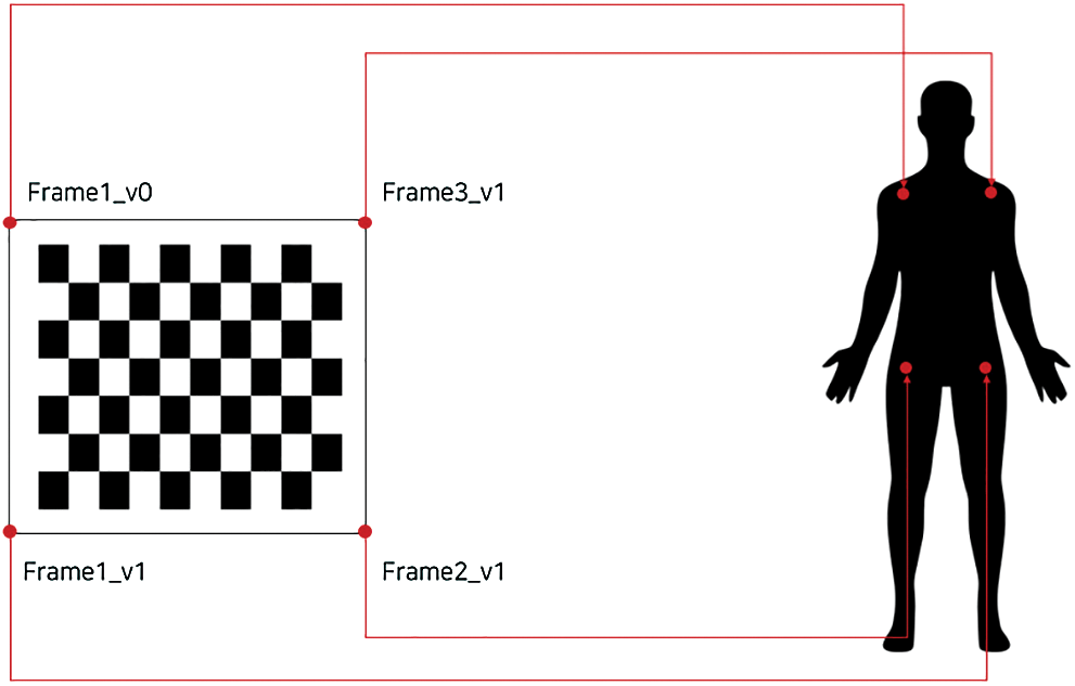
Figure 9: Mapping relation between the rectangular points of the image and joint points
4 Implementation and Experimental Results
4.1 Implementation Environment
In this study, we installed the Kinect V2 supporting infrared sensor, depth sensor, color camera, and BenQ MW846UST full high-definition (HD) 3D projector with 3000 ANSI. The Kinect sensor and the projector are installed at a distance, as shown in Fig. 10 (right). Additionally, a moving whiteboard was used for camera–projector calibration, as shown in Fig. 10 (left). For the experiments, the Kinect sensor and the projector were placed on the front of a moving whiteboard, and three matrices of homography were calculated at three depth levels in an area of 3 m × 3 m. The corner points of the chessboard were automatically detected in the camera image and the screen coordinates of the detected corner points were computed with the selected homography and Eq. (1).
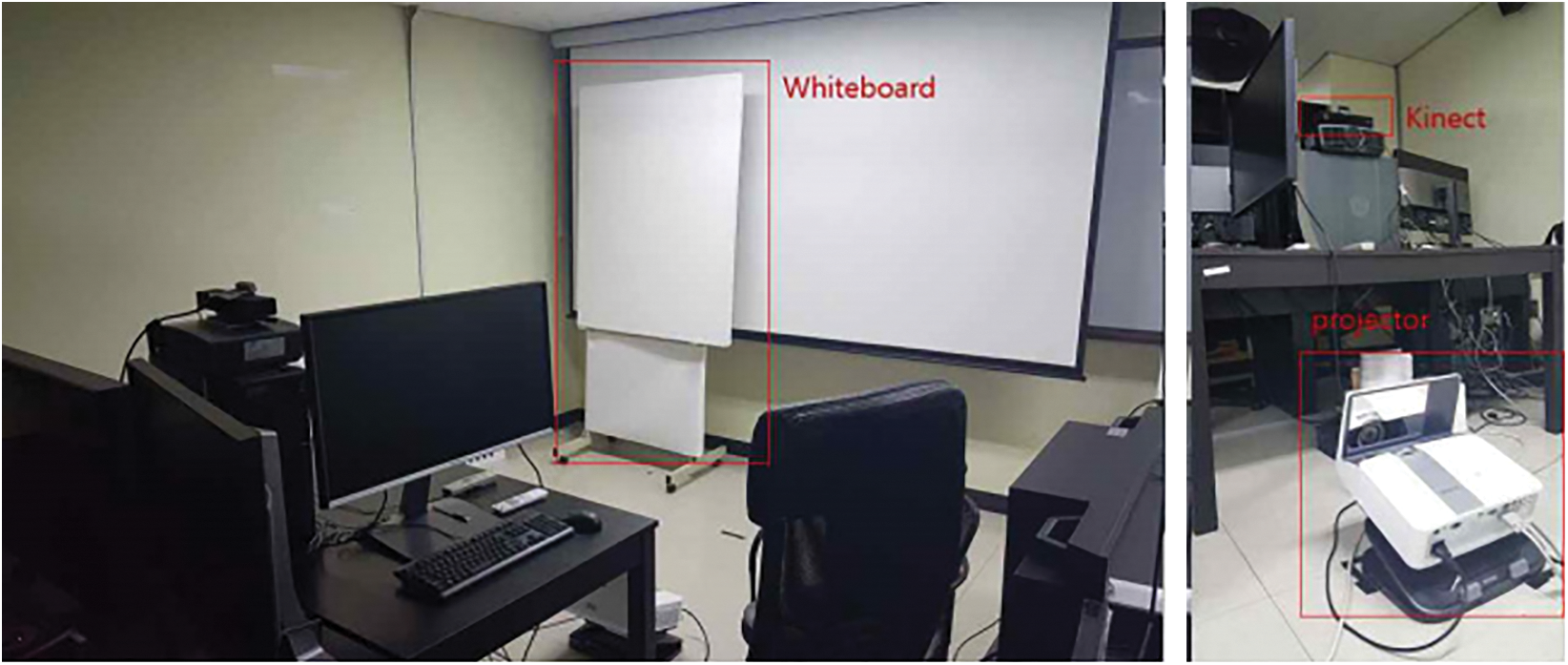
Figure 10: Movable whiteboard (left) and projector/Kinect setup (right)
4.2 Dynamic Projection Mapping for Single User
The first experiment mapped a red circle, an image, and a video to the user’s body with the use of the joint coordinates of the left/right shoulder, left/right pelvis, and both user hands. Fig. 11 shows mappings on the body with the use of red circles and videos. Fig. 11a is a picture showing one hand in the upward position and one in the downward position, and Fig. 11b is the picture showing both hands raised.
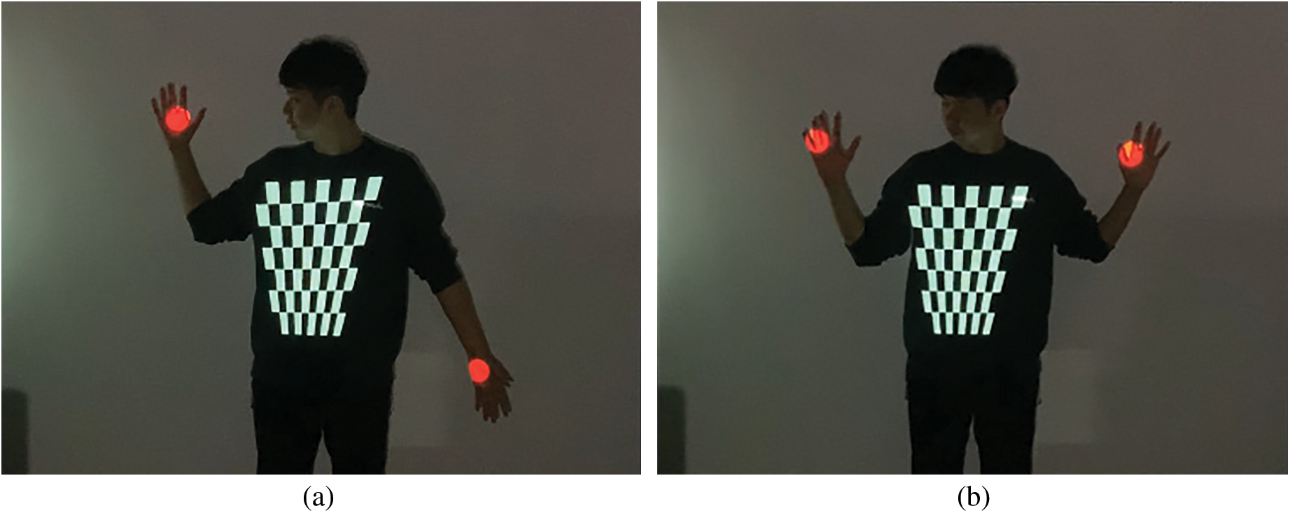
Figure 11: Mapping red circles and video onto a single user’s body. (a) A picture with one hand up and one hand down. (b) A picture with both hands up
4.3 Dynamic Projection Mapping for Multiple Users
The second experiment was conducted to map the red circle and image to the body using the left/right shoulder, left/right pelvis, and hand joints for both hands of multiple users. Fig. 12 shows the red circle and the image mapped accurately on the two user bodies.
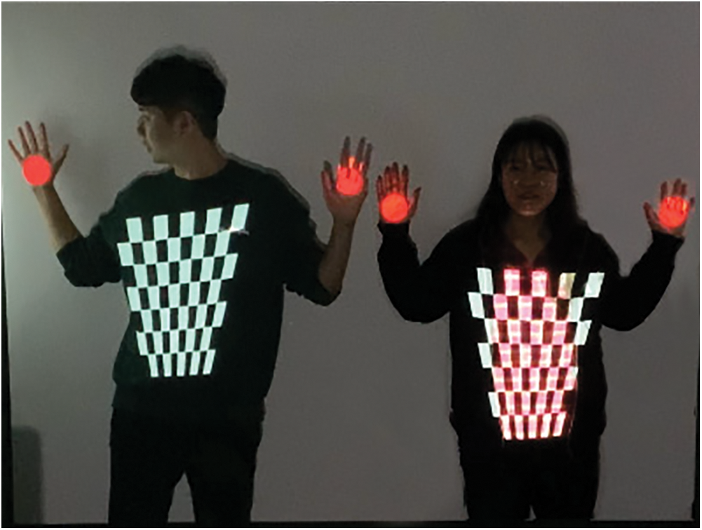
Figure 12: Mapping red circles and images onto two the bodies of two users
4.4 Dynamic Projection Mapping Results by User Distance
The third experiment mapped a red circle and an image to the user’s body with the use of a single user’s left/right shoulder, left/right pelvis, and the joints of both hands, with the use of the homography selection method according to depth-level classification and one without depth-level classification. Fig. 14 shows the application method with one homography and without depth-level classification. Experimentation was conducted with the use of the mapping according to the user’s distance and the movement of both hands. Fig. 13a shows the closest distance to the Kinect and the projector. Fig. 13b shows the intermediate distance. Fig. 13c shows the projection from the longest distance. Fig. 13d is an image with both hands lowered, while Fig. 13e shows the user with both hands stretched forward. Figs. 13b and 13d show images in which the chessboard pattern is appropriately mapped. Figs. 13a and 13c depict images in which the chessboard and circles are erroneously mapped. Fig. 13e shows a correct mapping of the chessboard and incorrect mappings of the circles on both hands. In Fig. 14, the homography selection method was tested based on depth-level classification, and in the same way as the case in which only one homographic method was used. The experimental results show that all the images in Figs. 14a–14e map normally, unlike the method that used only one homography.
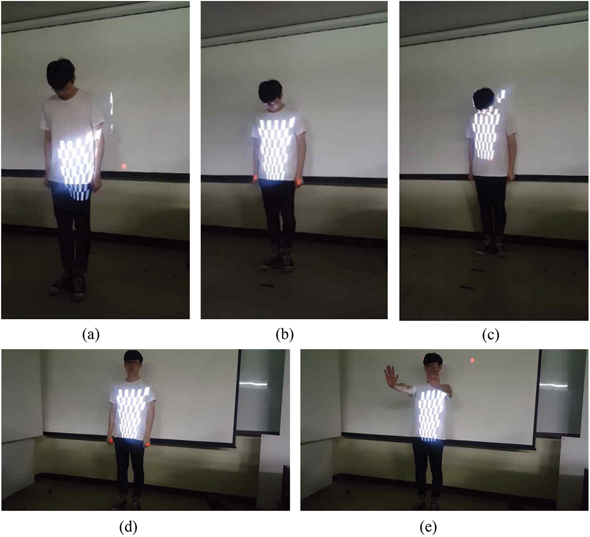
Figure 13: Mappings with the use of one homography without depth-level classification. (a) Third depth region. (b) Second depth region. (c) First depth region. (d) An image of the user with both of his hands lowered. (e) An image of the user image with both of his hands stretched forward
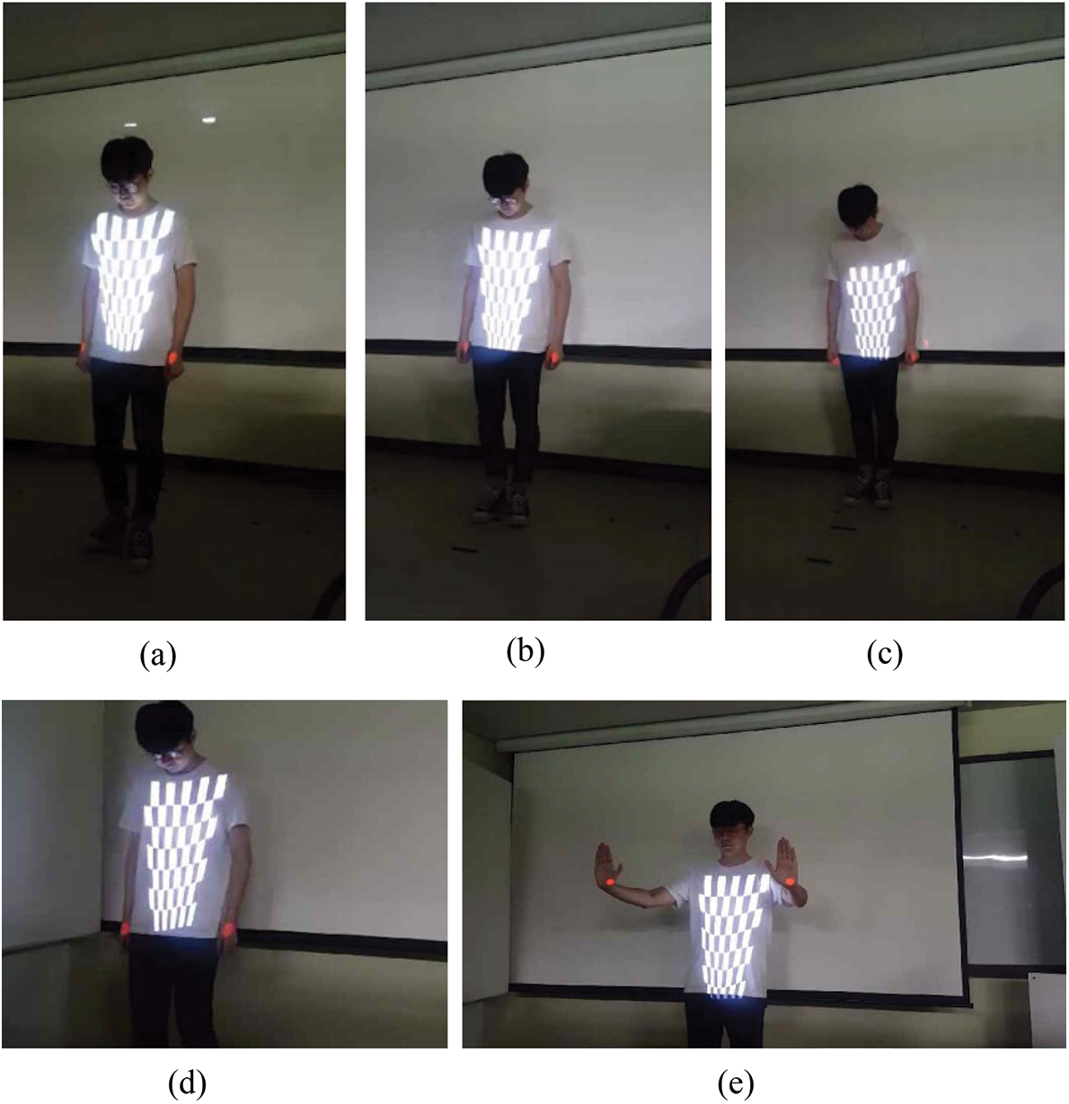
Figure 14: Mapped using homography according to depth-level classification. (a) Third depth region. (b) Second depth region. (c) First depth region. (d) An image of the user image with both of this hands lowered. (e) An image of the user image with both of his hands stretched forward
We also developed a 3D wing model in which the position and the orientation were controlled by the left and right shoulder joints. Fig. 15 shows the wing model which is displayed from different viewpoints, while Fig. 16 depicts the projections of the wing models on the left and right shoulder joints of the user.
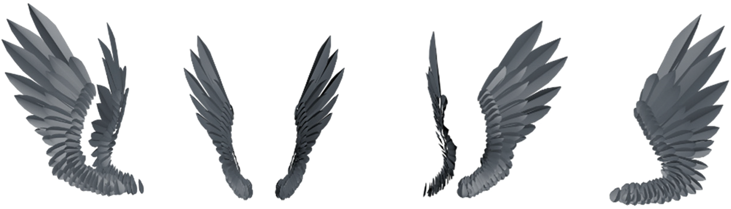
Figure 15: Displays of the 3D wing model at different viewpoints

Figure 16: Dynamic projection of the 3D wing model on the user shoulder joints
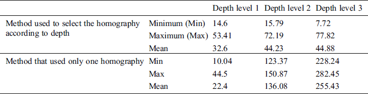
Tab. 1 shows the projection errors of the homography selection method based on depth-level classification and the correction outcomes of the method with one homography without depth-level classification. To measure the projection errors, we projected 54 points on the printed chessboard. These 54 projected points refer to the points of the screen space matched to the corner points extracted from the camera image after the printed chessboard was captured with a camera. After capturing the image that included the 54 projected points and the printed chessboard, we measured the distances between the matched points in the captured image. The use of the selection method indicated that the average projection error at each depth level is similar to the projection error at other depth levels. The method which used one homography showed that the average projection error was low only at one depth level, while the average errors at all the other depth levels increased abruptly. Fig. 17 shows bar graphs of the projection errors.
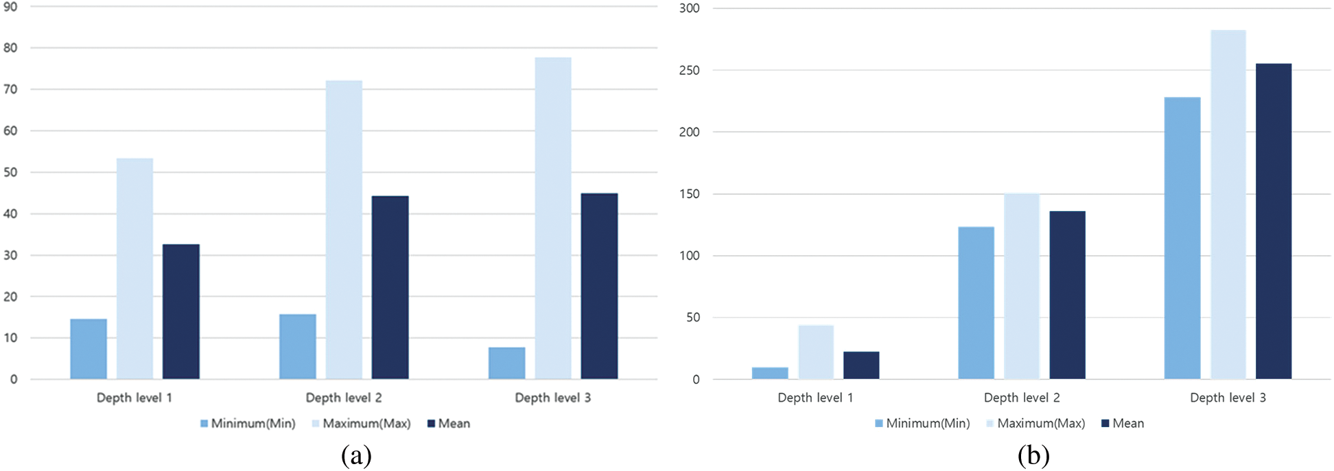
Figure 17: Comparisons of projection errors. (a) Method that selects the homography according to depth. (b) Method that uses only one homography
Table 1: Projection errors at different depth levels
Projection mapping is one of the AR fields. It is actively used in diverse fields, such as advertising, exhibitions, and performances. Early projection mapping has been used in the outer wall of a building or in a general object in a static form, but with the development of technology, it is possible to project media content in a dynamic form on the body, face, and clothes of a moving person. However, unlike static projection mapping, there are no commercialized tools that can be used for dynamic projection mapping. Therefore, to create dynamic mapping programs, convoluted programming tasks and complex camera-projector calibrations are needed. Correspondingly, in this study, we proposed a dynamic projection mapping content authoring tool that can easily produce dynamic projection mapping contents. The proposed tool uses Kinect’s RGB-D images to design and implement a new camera–projector calibration rather than a complex camera–projector calibration. The camera–projector calibration method implemented herein did not use the printed chessboard. Instead, it projected the chessboard to a moving whiteboard, captured the projected chessboard with the camera, and identified the corner point of the chessboard within the captured image. It then identified the corner point of the chessboard within the display image and stored the coordinate value and depth information. Furthermore, we repeated the method according to each camera depth level to obtain homography. Based on the stored depth information, we averaged the corner points for each depth level and searched for the tracked user joints to compare the depth information and depth values of the tracked joints to identify the depth levels they corresponded to. Based on the use of the homography at the corresponding depth level, either the image or the video specified in the configuration file was mapped to the joint. To prove the accuracy and convenience of the proposed system, we experimented with various single and multiuser poses, and successfully mapped the joints.
In our future work, we will investigate the robust and natural joint tracking methods at different depth levels. Additionally, we plan to study how IR markers are attached to free-strained objects (typically cloth or paper), track and map them with infrared sensors on the Kinect, and identify ways to minimize mapping delays.
Funding Statement: This work was partially supported by the Basic Science Research Program through a National Research Foundation of Korea (NRF) grant funded by the Ministry of Education (NRF-2017R1D1A1B03035718), and was partially supported by another National Research Foundation of Korea (NRF) grant funded by the Korean government (MIST) (NRF-2019R1F1A1062752).
Conflicts of Interest: The authors declare that they have no conflicts of interest to report regarding the present study.
1D. Yao, D. Park, S. An and S. K. Kim. (2019), “Development of augmented reality indoor navigation system based on enhanced A* algorithm. ,” KSII Transactions on Internet and Information Systems, vol. 13, no. (9), pp, 4606–4623, . [Google Scholar]
2S. Kim, M. Billinghurst, C. Lee and G. Lee. (2018), “Using freeze frame and visual notifications in an annotation drawing interface for remote collaboration. ,” KSII Transactions on Internet and Information Systems, vol. 12, no. (12), pp, 6034–6056, .
3J. Chun and B. Lee. (2010), “Dynamic manipulation of a virtual object in marker-less AR system based on both human hands. ,” KSII Transactions on Internet and Information Systems, vol. 4, no. (4), pp, 618–632, . [Google Scholar]
4R. T. Azuma. (1997), “A survey of augmented reality. ,” PRESENCE: Virtual and Augmented Reality, vol. 6, no. (4), pp, 355–385, . [Google Scholar]
5X. Duan, S. Kang, J. Choi and S. Kim. (2020), “Mixed reality system for virtual chemistry lab. ,” KSII Transactions on Internet and Information Systems, vol. 14, no. (4), pp, 1673–1688, . [Google Scholar]
6J. Lee, J. Lee, J. Lim and M. Kim. (2019), “Bandwidth-efficient live virtual reality streaming scheme for reducing view adaptation delay. ,” KSII Transactions on Internet and Information Systems, vol. 13, no. (1), pp, 291–304, . [Google Scholar]
7O. Bimber and R. Ramesh, “Spatial augmented reality. ,” in Spatial Augmented Reality: Merging Real and Virtual Worlds, 1st ed., Wellesley, Massachusetts, USA: A.K. Peters, pp. 7–8, 2005. [Google Scholar]
8G. Narita, Y. Watanabe and M. Ishikawa. (2017), “Dynamic projection mapping onto deforming non-rigid surface using deformable dot cluster marker. ,” IEEE Transactions on Visualization and Computer Graphics, vol. 23, no. (3), pp, 1235–1248, . [Google Scholar]
9J. Lee, Y. Kim and D. Kim. (2014), “Real-time projection mapping on flexible dynamic objects. ,” in Proc. of HCI Korea Conf., Jung Sun, South Korea, pp, 187–190, . [Google Scholar]
10L. Miyashita, Y. Watanabe and M. Ishikawa. (2018), “MIDAS projection: markerless and modeless dynamic projection mapping for material representation. ,” ACM Transactions on Graphics, vol. 37, no. (6), pp, 1–12, .
11Y. Mikawa, T. Sueishi, Y. Watanabe and M. Ishikawa. (2020), “Projection mapping system to a widely dynamic sphere with circumferental markers. ,” in Proc. of 2020 IEEE Int. Conf. on Multimedia and Expo, Virtual On-line Conference, pp, 1–6, . [Google Scholar]
12P. T. Fischer, S. Kuliga, M. Eisenberg and I. Amin. (2018), “Space is part of the product: using AttrackDiff to identify spatial impact on user experience with media facades. ,” in Proc. of the 7th ACM Int. Sym. on Pervasive Displays, New York, NY, USA, pp, 1–8, . [Google Scholar]
13A. B. Kurultay. (2012), “Dynamics of viral advertising. ,” Turkish Online Journal of Design Art and Communication, vol. 2, no. (2), pp, 39–45, . [Google Scholar]
14Y. Sohn, Y. Park, L. Lin and M. Jung. (2020), “Eternal recurrence: development of a 3D water curtain system and real-time projection mapping for a large-scale systems artwork installation. ,” Digital Creativity, vol. 31, no. (2), pp, 133–142, . [Google Scholar]
15C. Siegl, M. Colaianni, L. Thies and J. Thies. (2015), “Real-time pixel luminance optimization for dynamic multi-projection mapping. ,” ACM Transactions of Graphics, vol. 34, no. (6), pp, 1–11, . [Google Scholar]
16Y. Zhou, S. Xiao, N. Tang, Z. Wei and X. Chen. (2016), “Pmomo: Projection mapping on movable 3D object. ,” in Proc. of the 2016 CHI Conf. on Human Factors in Computing Systems, pp, 781–790, . [Google Scholar]
17Y. I. Abdel-Aziz, H. M. Karara and M. Hauck. (2015), “Direct linear transformation from comparator coordinates into object space coordinates in close-range photogrammetry. ,” Photogrammetric Engineering & Remote Sensing, vol. 81, no. (2), pp, 103–107, . [Google Scholar]
18Z. Zhang. (2000), “A flexible new technique for camera calibration. ,” IEEE Transactions on Pattern Analysis and Machine Intelligence, vol. 22, no. (11), pp, 1330–1334, . [Google Scholar]
19L. Yang, J. M. Normand and G. Moreau. (2016), “Practical and precise projector-camera calibration. ,” in Proc. of 2016 IEEE Sym. on Mixed and Augmented Reality, Merida, Yucatan, Mexico, pp, 63–70, . [Google Scholar]
20G. Falcao, N. Hurtos and J. Massich. (2008), “Plane-based calibration of a projector-camera system. ,” VIBOT Master, vol. 9, pp. 1–12, . [Google Scholar]
21M. Ashdown and Y. Sato. (2005), “Steerable projector calibration. ,” in Proc. of 2005 IEEE Computer Society Conf. on Computer Vision and Pattern Recognition, San Diego, CA, USA, pp, 98, . [Google Scholar]
22P. Song, S. Winkler and J. Tedjokusumo. (2007), “A tangible game interface using projector-camera systems. ,” Human-Computer Interaction. Interaction Platforms and Techniques, Lecture Notes in Computer Science, vol. 4551, pp, 956–965, . [Google Scholar]
23I. J. Jo, J. Lee and Y. J. Choi. (2016), “Simple method of video mapping of multiple targets, Advances in Computer Science and Ubiquitous Computing. ,” Advances in Computer Science and Ubiquitous Computing, Lecture Notes in Electrical Engineering, vol. 421, pp, 665–673, . [Google Scholar]
 | This work is licensed under a Creative Commons Attribution 4.0 International License, which permits unrestricted use, distribution, and reproduction in any medium, provided the original work is properly cited. |