DOI:10.32604/cmc.2020.012800
| Computers, Materials & Continua DOI:10.32604/cmc.2020.012800 | |
| Article |
Design of a Compact Monopole Antenna for UWB Applications
1Department of Electrical Engineering, Iqra National University, Peshawar, 25000, Pakistan
2Department of Electrical Engineering, City University of Science and Information Technology, Peshawar, 25000, Pakistan
3Department of Electronic Engineering, The Islamia University of Bahawalpur, Bahawalpur, 63100, Pakistan
4Department of Electrical Engineering, Multimedia University, Cyberjaya, 63100, Malaysia
5Department of Computer Science, Bacha Khan University, Charsadda, 24420, Pakistan
6School of Electrical Engineering, University of Ulsan, Ulsan, 44610, Korea
*Corresponding Author: Sunghwan Kim. Email: sungkim@ulsan.ac.kr
Received: 13 July 2020; Accepted: 16 August 2020
Abstract: In this paper, a low cost, highly efficient and low profile monopole antenna for ultra-wideband (UWB) applications is presented. A new inverted triangular-shape structure possessing meander lines is designed to achieve a wideband response and high efficiency. To design the proposed structure, three steps are utilized to achieve an UWB response. The bandwidth of the proposed antenna is improved with changing meander lines parameters, miniaturization of the ground width and optimization of the feeding line. The measured and simulated frequency band ranges from 3.2 to 12 GHz, while the radiation patterns are measured at 4, 5.3, 6 and 8 GHz frequency bands. The overall volume of the proposed antenna is 26 × 25 × 1.6 mm3; whereas the FR4 material is used as a substrate with a relative permittivity and loss tangent of 4.3 and 0.025, correspondingly. The peak gain of 4 dB is achieved with a radiation efficiency of 80 to 98% for the entire wideband. Design modelling of proposed antenna is performed in ANSYS HFSS 13 software. A decent consistency between the simulated and measured results is accomplished which shows that the proposed antenna is a potential candidate for the UWB applications.
Keywords: Ultra-wideband (UWB); meander lines; monopole antenna; high efficiency; high gain; ANSYS HFSS
Owing to the recent developments in wireless communication, the demand of antennas with a higher bandwidth is progressing day by day to cover multiple applications with a high performance capability [1–3]. The constant growth of wireless communication technology and higher data rates demand have diverted the attention of researchers towards the wideband antennas, covering more than one frequency band [4–6]. Since the spectrum from 3.1 to 10.6 GHz has been officially allocated by Federal Communication Commission (FCC) in 2002 for the ultra-wideband (UWB) communication applications [7–9]; the wireless personal area networks (PAN) are considering the UWB radio as a most promising candidate [10]. With the characteristics of better channel capacity at the partial range, low cost [11], low energy consumption [12], and new potentials for many applications such as low data rate communication with low power consumption and location and tracking (LDR-LT) [13], the Body Area Network (BAN) for medical applications [14], and the real time location systems (RTLS) using RFID technology to enhance the performance of container terminal operation [15] or make the hospital emergency response more efficient [16]. The role of an antenna realized in a UWB system is more vital and unique than the conventional narrowband systems. Also, the planar structures offer characteristics like light-weight, ease of fabrication and low-profile to provide an easy and quick wireless access for multimode communication systems.
In literatures [17–25], several antennas have been reported for the UWB applications. Reference [17] reports a bio inspired UWB antenna with an overall size of 314 × 121 mm2, comprising a leaf shape geometry and exhibiting a wideband response from 3.4 to 8 GHz having gain of 3.63 dB. Similarly, a UWB antenna operating at a wide frequency band of 3.4 to 15 GHz is presented with a total size of 31 × 22 mm2 [18] with gain variations. Reference [19] presents a symmetric open slot antenna with a total size of 29 × 20 mm2 for UBW applications, covering a frequency band from 3.1–10.8 GHz. Furthermore, gain is observed varying from 3.9 to 5.7 dB for the desired wideband response. Likewise, a UWB antenna with an overall size of 34 × 33 mm2 is proposed with a maximum measured gain of 4.35 dB [20]. But an inconsistency is observed in the proposed design measured gain for the entire wideband response. Moreover, a z-shaped UWB antenna with a total size of 38 × 35 mm2 is reported showing 1.6–6.4 dB gain [21]. But a mismatch in impedance is observed near the 8 and 11 GHz frequency bands for the FCC allotted UWB range. Reference [22] presents an elliptical ring monopole antenna for the UWB communications with a ground plane size of 100 × 100 mm2. The average gain of 3.9 dB is achieved for the desired UWB spectrum. Similarly, the UWB antenna design covering the frequency band approximately from 4 to 4.5 GHz is proposed in [23], while the M-shaped antenna operating at the frequency band of 3.25 to 8.85 GHz [24] and a V-shaped monopole antenna with a peak gain of 2 dB is presented in [25]. According to the above literature review, it is analyzed that the reported antennas for the UWB applications are either complex or large in structure. Furthermore, some of them achieve a satisfactory impedance bandwidth but they possess a low gain for the desired frequency band.
In this paper, we present a novel planar monopole antenna possessing a satisfactory gain and impedance bandwidth with a modified defected ground structure for the UWB applications. The UWB response is achieved by optimizing the radiating patch into an inverted triangular shaped structure with an insertion of two I shaped meander lines on front radiating patch. The ground plane is introduced with a square shape slot and is adjusted parametrically to observe a UWB resonance. The outline of the remaining paper is organized as following manner. Section 2 presents the geometry of the proposed planar monopole antenna design with a detailed discussion on the design evolution steps and parametric modeling. The simulated and measured results are discussed in Section 3 while conclusion is made in Section 4.
Substrate selection can be vital consideration in the antenna design process [26,27]. The Proposed monopole antenna (Fig. 1) is designed on the low loss FR4 substrate, having relative permittivity and thickness of 4.3 and 1.6 mm, correspondingly. The ground plane and radiating element of the monopole antenna are covered with copper sheet with a standard thickness of 0.035 mm. The inverted triangular shape structure with a meandered strip is introduced to achieve a higher bandwidth response and stable radiation patterns with enhanced performance characteristics. The antenna is fed by a 50-ohm transmission line having thickness of 3 mm. The overall volume of the proposed antenna is 26 mm × 25 mm × 1.6 mm. The design parameters of the antenna as shown in Fig. 1 are: A = 26 mm, B = 25 mm, C = 6 mm, D = 5.5 mm, E = 3 mm, F = 6.03 mm, G = 1 mm.
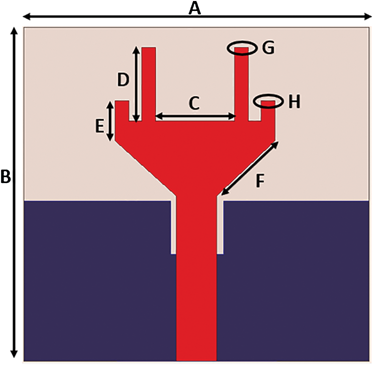
Figure 1: Proposed UWB antenna
The proposed monopole structure evolution steps are discussed in this section as shown in Fig. 2, while their reflection coefficients are compared in Fig. 3. At first stage, a simple monopole antenna with a partial ground plane is designed, operating at a resonant frequency of 4 GHz with a 250 MHz impedance bandwidth. A rectangular shape slot is introduced at the second stage which transform the bandwidth response achieved at stage one to a wideband ahead of 6.5 GHz. Finally, at stage three, two mini and large strips are introduced which make the response achieved at stage two, ultra-wideband; covering the frequency band from 3.2 to 12 GHz.
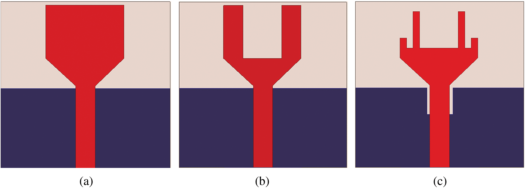
Figure 2: Proposed monopole antenna design evolution steps. (a) stage one, (b) stage two, (c) stage three
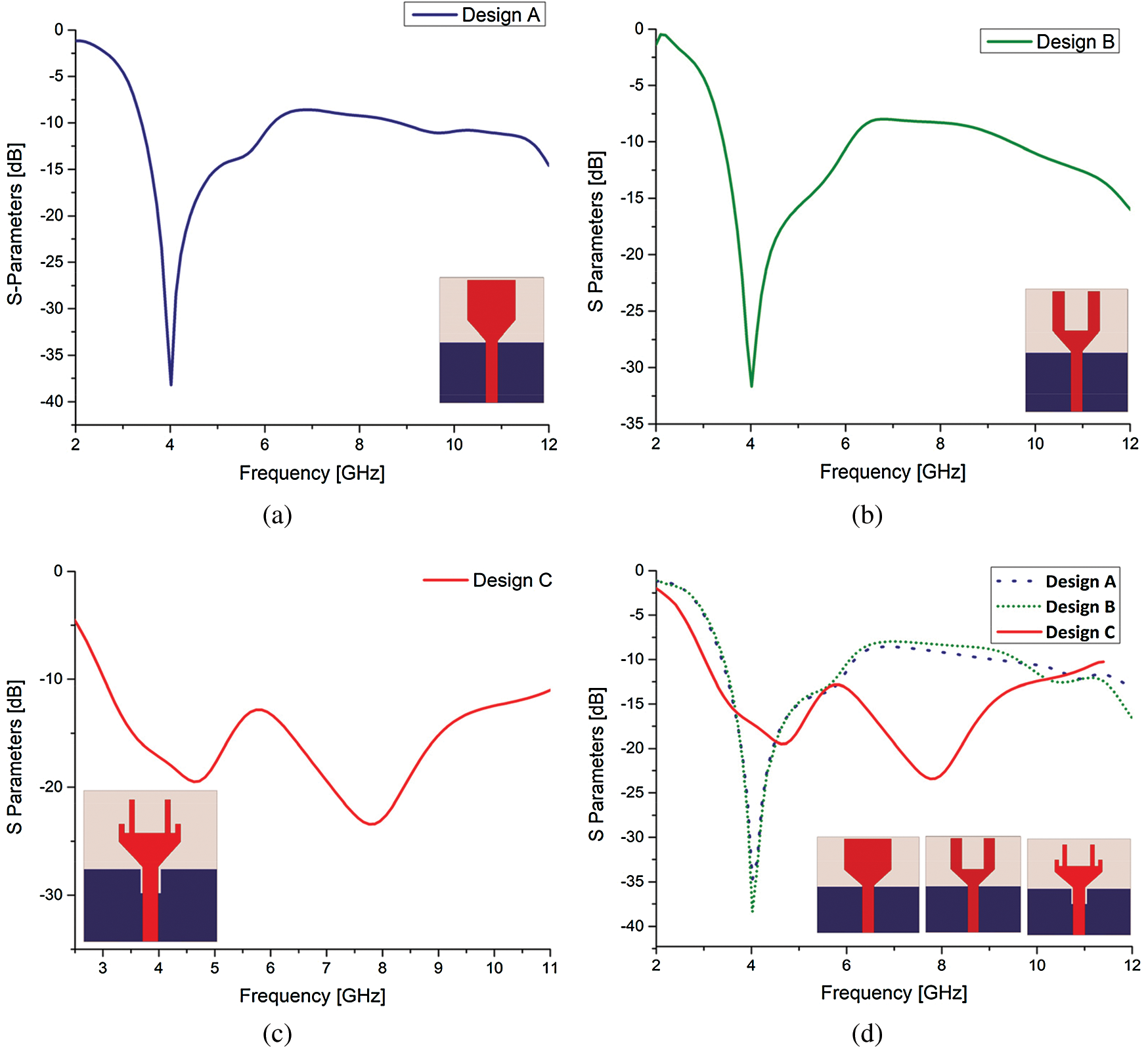
Figure 3: Reflection coefficient comparison. (a) stage one, (b) stage two, (c) stage three, (d) overall comparison
2.2 Effect of Ground Plane Square Slot
To achieve a UWB response, the design aspects of proposed design are studied parametrically. The one of the main design aspects, i.e., ground plane square slot (GC) is discussed in this section. The S-parameter response of the above study is depicted in Fig. 4. At first, the ground slot of 3 mm length in the middle of partial ground is introduced which gives two resonances at the central frequencies of nearly 5 and 9 GHz whereas an impedance discrepancy is seen over the frequency band ranging from 6 to 8 GHz which is improved by introducing the slot of 3.5 mm length but giving an impedance from 9 to 10 GHz frequency band. The further improvement in the reflection coefficient response is observed by increasing the length of the slot up to 4 mm. A good ultra-wideband response is achieved covering 3.8 to 11 GHz. At 4.5 mm length, the proposed antenna gives a wideband response ranging from 3.8 to 8.5 GHz with another frequency band of 10.3 GHz. Whereas a similar response is observed at the 5 mm length for 3.8 to 8.5 GHz frequency band with an improved reflection coefficient response at the 10.3 GHz frequency band up to −45 dB.
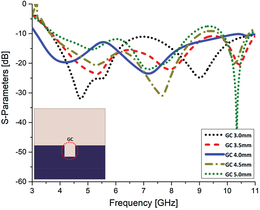
Figure 4: Reflection coefficient response with different ground square cut (GC) values
2.3 Effect of Rectangular Slot on the Radiating Element
This section presents the parametric study of the radiating element square cut (PSC), starting with the base value of 10 mm; the first resonance is achieved at the central frequency of 9 GHz which is further modeled. At 1 mm further increase in the upper square cut nearly a linear type response is observed. Although, it is a wideband response ranging from a frequency band of 3.6 GHz to onwards of the range targeted for the ultra-wideband. At 12 mm square cut value, the proposed design achieves UWB response with a shift in resonances downward and improved reflection coefficient response at the 4 GHz frequency band. The square cut of the radiating element is further modeled in order to achieve further higher bandwidth but as the size of the square cut is increased, the reflection coefficient becomes unstable and starts to exhibit notch type characteristics. At 12.5 mm square cut value, the bandwidth is reduced to 3 GHz; covering the frequency band from 7 GHz to 10.5 GHz. Whereas the refection coefficient response is transformed to dual band with no resonance from 8.5 to 9.5 GHz frequency band. As it can be seen in Fig. 5 that only at 12 mm square cut value, a proper UWB response is achieved.
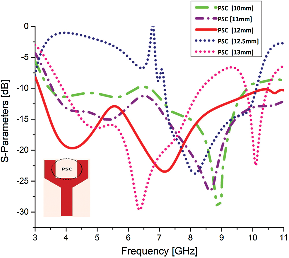
Figure 5: Reflection coefficient response with different radiating element rectangular cut values (PSC)
In this section, the proposed ultra-wideband antenna results such as reflection coefficient, radiation patterns and radiation efficiency are discussed.
The fabricated prototype of the proposed antenna is shown in Fig. 6. To validate the simulated results, antenna is tested and a good resemblance between the simulated and measured reflection coefficient is achieved. The minor dissimilarity between the simulated and measured results occur due to the cable and fabrication losses.
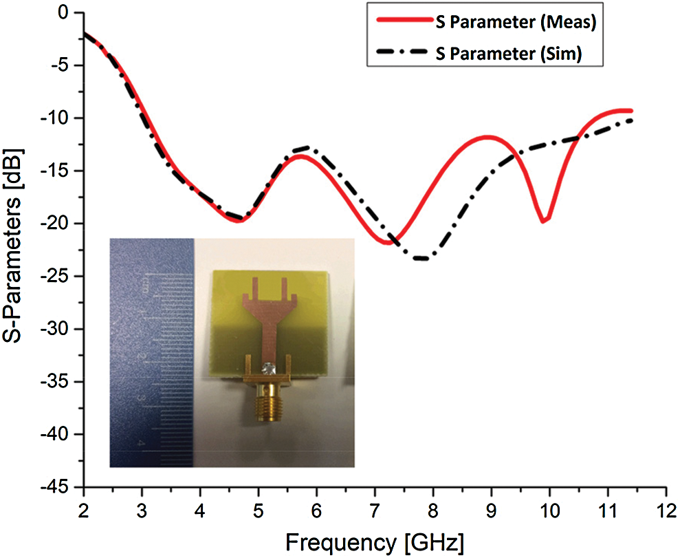
Figure 6: Simulated and measured reflection coefficient
Fig. 7 presents the measured and simulated radiation patterns. The gain patterns are analyzed at the frequency bands of 4, 5.3, 6 and 8 GHz in the two principle planes, i.e., E and H plane. As it can be seen that the radiation patterns are nearly omnidirectional at the desired frequency bands. A good coherence among patterns is observed, while a minor dissimilarity is due the fabrication errors or unavoidable use of cables during the measurement process. The peak gain of 4 dB is achieved for the desired ultra-wideband.
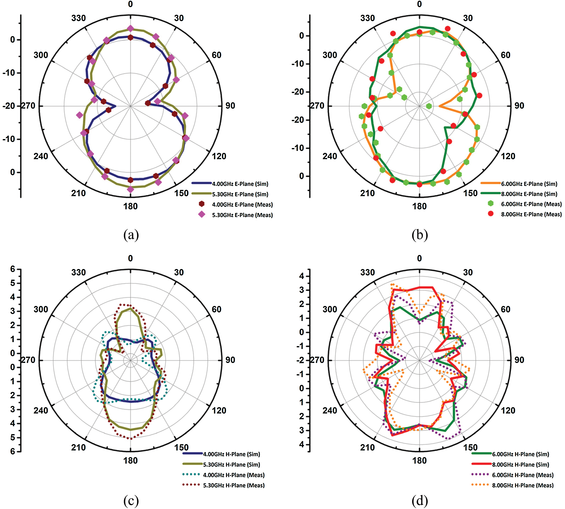
Figure 7: Simulated and measured radiation patterns at (a) 4 and 5.3 GHz (phi = 0 deg.), (b) 6 and 8 GHz (phi = 0 deg.), (c) 4 and 5.3 GHz (phi = 90 deg.), (d) 6 and 8 GHz (phi = 90 deg.)
4 Surface Current Distribution
The surface current distribution of the proposed design is analyzed at the frequency bands of 4, 5.3, 6 and 8 GHz as shown in Fig. 8. From the surface current distribution, it is observed that the ground square slot as well as patch are contributing in wideband response achievement. At 4 GHz, the current is focused on the lower edges of V-shaped radiating element and at the I-shaped towers. The ground plane as a whole is induced with surface currents at the edges of its borders. On higher frequencies, the surface current distribution is mostly focused at the bottom of the V-shaped radiating element while the I-shaped towers also contain higher surface current intensity.
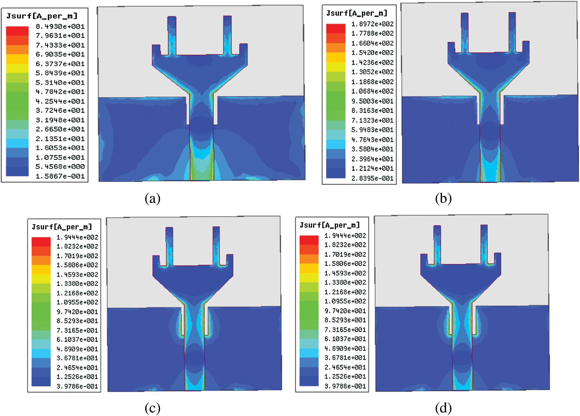
Figure 8: Surface current distribution at (a) 4 GHz, (b) 5.3 GHz, (c) 6 GHz, (d) 8 GHz
This paper presents a novel monopole antenna design fed by a 50 ohm microstrip transmission line with an overall dimension of 26 × 25 × 1.6 mm3 for the UWB applications. The antenna exhibits a wideband response with an insertion of a square cut in the ground plane and I-shaped stripes on the radiating element and is capable to operate at the frequency band of 3.2 to 12 GHz. Furthermore, a peak gain of 4 dB is achieved by the proposed antenna across the desired frequency band. Moreover, the proposed antenna is fabricated, and measured results are in well agreement with the simulated results which validate that the proposed antenna is a good contender for UWB applications. In future, the proposed antenna can be used in the Multiple Input Multiple Output (MIMO) configuration to achieve a pattern diversity.
Funding Statement: This work was supported by the Research Program through the National Research Foundation of Korea, NRF-2019R1A2C1005920, S. K.
Conflicts of Interest: The authors declare that they have no conflicts of interest to report regarding the present study.
References
1. W. A. Awan, A. Zaidi, N. Hussain, A. Iqbal and A. Baghdad. (2019). “Stub loaded, low profile UWB antenna with independently controllable notch-bands,” Microwave and Optical Technology Letters, vol. 61, no. 11, pp. 2447–2454.
2. A. Iqbal, O. A. Saraereh and S. K. Jaiswal. (2017). “Maple leaf shaped UWB monopole antenna with dual band notch functionality,” Progress in Electromagnetics Research, vol. 71, pp. 167–175.
3. J. Khan, D. A. Sehrai and U. Ali. (2019). “Design of dual band 5G antenna array with SAR analysis for future mobile handsets,” Journal of Electrical Engineering & Technology, vol. 14, no. 2, pp. 809–816.
4. D. A. Sehrai, M. Abdullah, A. Altaf, S. H. Kiani, F. Muhammad et al.. (2020). , “A novel high gain wideband mimo antenna for 5G millimeter wave applications,” Electronics, vol. 9, no. 6, pp. 1031.
5. C. Guo, W. Lu, Z. Zhang and L. Zhu. (2017). “Wideband non-traveling-wave triple-mode slotline antenna,” IET Microwaves, Antennas & Propagation, vol. 11, no. 6, pp. 886–891.
6. S. Koziel, S. Ogurtsov, W. Zieniutycz and A. Bekasiewicz. (2015). “Design of a planar UWB dipole antenna with an integrated balun using surrogate-based optimization,” IEEE Antennas and Wireless Propagation Letters, vol. 14, pp. 366–369.
7. L. Wang, K. H. Teng, Y. Lian and C. H. Heng. (2018). “A 4 × 4 IR UWB timed-array radar based on 16-channel transmitter and sampling capacitor reused receiver,” IEEE Transactions on Circuits and Systems II: Express Briefs, vol. 65, no. 7, pp. 878–882.
8. M. Rahman, A. Haider and M. Naghshvarianjahromi. (2020). “A systematic methodology for the time-domain ringing reduction in UWB band-notched antennas,” IEEE Antennas and Wireless Propagation Letters, vol. 19, no. 3, pp. 482–486.
9. X. Shan and Z. Shen. (2019). “Miniaturized UHF/UWB tag antenna for indoor positioning systems,” IEEE Antennas and Wireless Propagation Letters, vol. 18, no. 12, pp. 2453–2457.
10. R. Yahya, A. Nakamura, M. Itami and T. A. Denidni. (2017). “A novel UWB FSS-based polarization diversity antenna,” IEEE Antennas and Wireless Propagation Letters, vol. 16, pp. 2525–2528.
11. G. Srivastava and A. Mohan. (2016). “Compact MIMO slot antenna for UWB applications,” IEEE Antennas and Wireless Propagation Letters, vol. 15, pp. 1057–1060.
12. D. Bao, Z. Zou, M. Baghaei Nejad, Y. Qin and L. Zheng. (2018). “A wirelessly powered UWB RFID sensor tag with time-domain analog-to-information interface,” IEEE Journal of Solid-State Circuits, vol. 53, no. 8, pp. 2227–2239.
13. G. Srivastava, A. Mohan and A. Chakrabarty. (2017). “Compact reconfigurable UWB slot antenna for cognitive radio applications,” IEEE Antennas and Wireless Propagation Letters, vol. 16, pp. 1139–1142.
14. M. Shehata, M. S. Said and H. Mostafa. (2018). “Dual notched band quad-element MIMO antenna with multitone interference suppression for IR-UWB wireless applications,” IEEE Transactions on Antennas and Propagation, vol. 66, no. 11, pp. 5737–5746.
15. Y. Kim, J. Lee and S. Kim. (2016). “Modeling of UWB channel with population density in indoor LOS environments,” IEEE Antennas and Wireless Propagation Letters, vol. 15, pp. 1450–1453.
16. S. Kumar, R. D. Gupta and M. S. Parihar. (2016). “Multiple band notched filter using C-shaped and E-shaped resonator for UWB applications,” IEEE Microwave and Wireless Components Letters, vol. 26, no. 5, pp. 340–342.
17. J. N. Cruz, A. J. R. Serres, A. C. de Oliveira, G. V. R. Xavier, C. C. R. de Albuquerque et al.. (2019). , “Bio-inspired printed monopole antenna applied to partial discharge detection,” Sensors, vol. 19, no. 3, pp. 628.
18. P. S. Bakariya, S. Dwari and M. Sarkar. (2015). “Triple band notch UWB printed monopole antenna with enhanced bandwidth,” AEU International Journal of Electronics and Communications, vol. 69, no. 1, pp. 26–30.
19. S. Zhang, Y. Zhong, Y. Zhou, Y. Guo and C. Ji. (2019). “Design of a symmetric open slot antenna for UWB applications,” IEICE Electronics Express, vol. 16, no. 20, pp. 1–13.
20. A. Iqbal, A. Smida, N. K. Mallat, M. T. Islam and S. Kim. (2019). “A compact UWB antenna with independently controllable notch bands,” Sensors, vol. 19, no. 6, p. 1411.
21. S. Ullah, C. Ruan, M. S. Sadiq, T. U. Haq and W. He. (2020). “High efficient and ultra wide band monopole antenna for microwave imaging and communication applications,” Sensors, vol. 20, no. 1, pp. 115.
22. K. Nakprasit, A. Sakonkanapong and C. Phongcharoenpanich. (2020). “Elliptical ring antenna excited by circular disc monopole for UWB communications,” International Journal of Antennas and Propagation, vol. 2020, pp. 1–11.
23. M. Frank, F. Lurz, M. Kempf, J. Rober, R. Weigel et al.. (2020). , “Miniaturized ultra-wideband antenna design for human implants,” in IEEE Radio and Wireless Sym., San Antonio, TX, USA, pp. 48–51.
24. S. A. Omar, A. Iqbal, O. A. Saraereh and A. Basir. (2017). “An array of M-shaped vivaldi antennas for UWB applications,” Progress in Electromagnetics Research, vol. 68, pp. 67–72.
25. W. A. Awan, N. Hussain, S. A. Naqvi, A. Iqbal, R. Striker et al.. (2020). , “A miniaturized wideband and multi-band on-demand reconfigurable antenna for compact and portable devices,” AEU International Journal of Electronics and Communications, vol. 122, pp. 153266.
26. M. Abdullah, S. H. Kiani and A. Iqbal. (2019). “Eight element multiple input multiple output (MIMO) antenna for 5G mobile applications,” IEEE Access, vol. 7, pp. 134488–134495.
27. M. Abdullah, S. H. Kiani, L. F. Abdulrazak, A. Iqbal, M. A. Bashir et al.. (2019). , “High-performance multiple-input multiple-output antenna system for 5G mobile terminals,” Electronics, vol. 8, pp. 1090.
 | This work is licensed under a Creative Commons Attribution 4.0 International License, which permits unrestricted use, distribution, and reproduction in any medium, provided the original work is properly cited. |