DOI:10.32604/cmc.2020.013132
| Computers, Materials & Continua DOI:10.32604/cmc.2020.013132 | |
| Article |
Fingerprint-Based Millimeter-Wave Beam Selection for Interference Mitigation in Beamspace Multi-User MIMO Communications
1Department of Electronic Engineering, Chonnam National University, Gwangju, 61186, Korea
2Hancom With Inc., Seongnam-si, 13493, Korea
3Division of Information & Telecommunication, Hanshin University, Osan-si, 18101, Korea
*Corresponding Author: Intae Hwang. Email: hit@jnu.ac.kr
Received: 27 July 2020; Accepted: 22 August 2020
Abstract: Millimeter-wave communications are suitable for application to massive multiple-input multiple-output systems in order to satisfy the ever-growing data traffic demands of the next-generation wireless communication. However, their practical deployment is hindered by the high cost of complex hardware, such as radio frequency (RF) chains. To this end, operation in the beamspace domain, through beam selection, is a viable solution. Generally, the conventional beam selection schemes focus on the feedback and exhaustive search techniques. In addition, since the same beam in the beamspace may be assigned to a different user, conventional beam selection schemes suffer serious multi-user interference. In addition, some RF chains may be wasted, since they do not contribute to the sum-rate performance. Thus, a fingerprint-based beam selection scheme is proposed to solve these problems. The proposed scheme conducts offline group-based fingerprint database construction and online beam selection to mitigate multi-user interference. In the offline phase, the contributing users with the same best beam are grouped. After grouping, a fingerprint database is created for each group. In the online phase, beam selection is performed for purposes of interference mitigation using the information contained in the group-based fingerprint database. The simulation results confirm that the proposed beam selection scheme can achieve a signal-to-interference-plus-noise ratio and sum-rate performance which is close to those of a fully digital system, and having much higher energy efficiency.
Keywords: Beam selection; beamspace; group-based fingerprint; interference mitigation; millimeter-wave
The emergence of fifth-generation (5G) mobile communication technology is promising to fulfill requirements and support various services, including enhanced mobile broadband (eMBB), massive machine-type communications (mMTC), and ultra-reliable low-latency communications (URLLCs), to facilitate the rapid growth in data usage and the development of new application services. The eMBB is designed to provide the users with a new experience through ultrahigh-definition holograms and virtual-reality content, especially in hotspot areas with a high user density and low mobility. In the case of mMTC, low-cost Internet of Things (IoT) devices with long battery life are proposed to support the short-burst machine-type communication traffic, which may be less sensitive to delay. In other words, 5G usage has been envisioned to facilitate efficient connectivity for numerous IoT devices at a low cost. The URLLC refers to cases of usage in areas such as industrial manufacturing, remote medical surgery, and safety in autonomous vehicles, all of which require enhanced capabilities in terms of throughput, latency, and availability [1,2]. Among these services, eMBB has attracted the most attention. It requires a maximum downlink transmission rate of 20 Gbps, which is approximately 20 times that of the fourth-generation (4G) systems, with a user-perceived transmission rate in the order of 100–1000 Mbps. The shorter wavelength of the millimeter-wave (mmWave) signals allow a base station to deploy tens or even hundreds of antennas in a relatively compact space, easily supporting massive multiple-input multiple-output (MIMO) systems [3]. Furthermore, the advantages of massive MIMO include increased data rate and link reliability [4], and improvements in the energy and spectral efficiencies by three orders and by one to two orders of magnitude, respectively [5]. The combination of mmWave and massive MIMO could effectively counter their respective shortcomings, while sufficiently exploiting the benefits. The latest research results demonstrate the potential of mmWave’s massive MIMO for 5G wireless systems [6,7].
The significant propagation and penetration losses suffered by mmWave communication can be compensated through techniques, such as directional beamforming (BF) [8–10]. The BF technique select the most suitable beam direction, which is created through multiple antenna elements for user equipment (UE), in order to maximize the transmission rate and improve energy efficiency. The traditional algorithms for mmWave beam selection are based on perfectly estimating the channel-state information (CSI), which requires accurate channel estimation and CSI feedback to the base station [11]. However, the traditional methods are greatly limited by the difficulty in capturing the real-time CSI for UE in mmWave transmission systems. In addition, the involved exhaustive beam search technique induces a large overhead and imposes a heavy computational burden on the system. Consequently, in recent years, new channel estimation algorithms for mmWave cellular systems have been developed. An adaptive compressed sensing (CS)-based algorithm, which estimates the parameters of mmWave channels efficiently was designed as in [12]. Through the adoption of a temporally correlated mmWave channel model, Alexandropoulos et al. [13] presents two CS algorithms that exploit the temporal correlation in order to reduce the complexity of sparse channel estimation. In addition, the beam searching process could be accelerated by either position or direction estimation. The authors of [14] presented an efficient method, which utilize the exchange of position information between the network nodes in the design of their BF and combining vectors. In [15], the concept of radar-aided mmWave vehicular communication is introduced, and two protocols used for beam searching in a vehicle-to-infrastructure (V2I) scenario were proposed. The simulation results confirmed that the main directions of arrival for the radar and communication signals were similar and that the radar could act as a useful source of side information for configuring the mmWave V2I link.
Among the challenges of realizing mmWave massive MIMO systems is the complexity of the hardware. Each antenna in the antenna array must be driven by a radio frequency (RF) chain, which forms a significant portion of the total system cost. In addition, the power consumption of an RF chain at mmWave frequencies is significantly higher than that at 6 GHz, making it practically prohibitive to have numerous RF chains [4,5]. In order to reduce the cost of hardware and power consumption, a lens antenna array was recently investigated for use as an energy-efficient realization of hybrid beamforming for mmWave massive MIMO. By using the lens antenna array at the transmitter, the spatial channel could be represented by the beamspace (i.e., angular domain). The beamspace channel is sparse, since the propagation of mmWaves is highly directional, occupying only a small number of directions. Since each beam in the beamspace corresponds to a single RF chain, we could reduce the number of RF chains without incurring considerable losses in the sum-rate performance, by appropriately selecting a small number of beams. In this regard, accurate beam selection is essential for beam-based mmWave communications. An enhanced spatial-division multiple access scheme, in which the base station selects several beams that capture the main lobe of the channel, was presented to estimate the original high-dimensional channel, thereby reducing the feedback [16]. Although this scheme could overcome the difficulty associated with the downlink CSI acquisition for a mmWave massive MIMO system, the computational complexity and feedback design have to be considered. Magnitude-maximization-based beam selection (MM-BS) was proposed in [17]. In MM-BS, several beam widths of large magnitude are selected for each user. Despite its simplicity, MM-BS has two problems: i) It only aims to retain the power of each user as much as possible, while not considering multi-user interference, which leads to a non-negligible performance loss in the achievable sum-rate; ii) Since different RF chains are likely to select the same beam, some RF chains can be wasted, because they do not contribute to the sum-rate performance.
In this paper, we propose a fingerprint-based mmWave beam selection technique, which requires less feedback and shuns the high computational complexity occasioned by an exhaustive search while suppressing multi-user interference in beamspace MIMO communications. The proposed beam selection scheme consists of two phases: i) An offline phase that creates a group-based fingerprint database; ii) An online beam selection through suppressing multi-user interference. In the offline phase, the contributing users having similar best beam is grouped. Afterwards, the fingerprint database for each group is created. In the online phase, beam selection is performed using the information contained in the group-based fingerprint database. The remainder of this paper is organized as follows: In Section 2, we introduce the system models for beamspace mmWave multi-user systems. In Section 3, the proposed fingerprint-based beam selection technique is described. The simulation results are presented in Section 4. Finally, the conclusion of this paper is presented in Section 5.
Consider a mmWave massive MIMO system in which the base station employs  antennas and
  RF chains to serve
  single-antenna users simultaneously. The received signal for all
  users in the spatial domain is given by:

where  is the channel matrix and
  is the channel vector between the base station and the
  -th user.
  is the digital precoding matrix,
  is the symbol vector with the normalized power
  , and the average power constraint is given by
  , where
  .
.  is an additive white Gaussian noise vector with
  . Based on the widely used Saleh–Valenzuela channel model for mmWave communications, the channel vector
  can be represented as follows [18,19]

where  is the line-of-sight (LoS) component and
  ,
,  is the
  -th non-LoS (NLoS) component.
 ,
,  , and
, and  are the complex gain, azimuth angle, and elevation angle, respectively.
  is the array steering vector. For a uniform planar array (UPA) with
  antennas, the equation is given by:

where 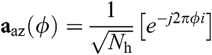 for
for  ,
, 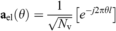 for
for  , and we defined
  . The spatial azimuth (elevation) angle is defined as ɸ ≜
 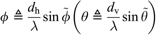 θ ≜ , where
  is the physical azimuth (elevation),
  is the wavelength of the carrier, and
  is the horizontal (vertical) antenna spacing. Generally, at mmWave frequencies,
  .
.
The spatial-domain channel can be directly transformed into the beamspace domain by employing a lens antenna array, as shown in Fig. 1. The lens antenna array acts as a spatial discrete Fourier transform matrix  of size
  , containing the array response vectors of the orthogonal directions covering the entire space as follows:
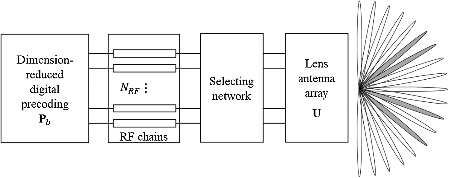
Figure 1: Block diagram of mmWave beamspace massive MIMO with  RF chains

where  for
for  and
and  for
for  presents the spatial azimuths and elevations predefined by the lens antenna array, respectively.
Finally, the beamspace system can be represented as follows:

where,  is the received signal vector in the beamspace domain, and the beamspace channel
  is defined as follows:

where  is the beamspace channel of the
  -th user. Notedly, the number of dominant scatters in the mmWave propagation environments is limited. Therefore, the number of NLoS components
  in (2) is much smaller than in
  ; thus, the beamspace channel has a sparse structure, i.e., the number of dominant elements of
  is much smaller than
  . Consequently, we can select only a small number of appropriate beams based on the sparse beamspace channel, in order to reduce the dimension of the MIMO system without apparent performance loss, as given below:

where  ,
,  contains the indexes of the selected beams, and
  is the dimension-reduced digital precoding matrix. Since the dimension of
  is much smaller compared to that of the original digital precoding matrix
  in Eq. (1), the beamspace MIMO can significantly reduce the number of RF chains required. Notedly, the smallest number of RF chains required to guarantee the spatial multiplexing gain of
  users is
  . As such, in this study, we consider
  without loss of generality.
3 Fingerprint-Based mmWave Beam Selection
To achieve high data-rate gains in mmWave communication systems, the deployment of large antenna arrays at the transmitters and/or receivers is required. The best beam pair for these arrays is normally determined by performing an exhaustive search over a large codebook of candidate beams. However, this leads to large training overheads [20,21]. Additionally, the same beam in the beamspace is likely to be selected for different users by different RF chains, causing serious multi-user interference.
In order to solve these problems, we propose a fingerprint-based beam selection scheme consisting of two phases, as shown in Fig. 2. The first consists of an offline phase to create the fingerprint database while the second one consists of an online beam selection through the control of multi-user interference. These phases are described in detail below.
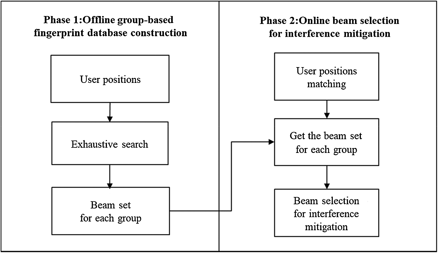
Figure 2: Fingerprint-based beam selection to mitigate multi-user interference
3.1 Fingerprint Database Construction
In the offline phase, the fingerprint database is created. Generally, a fingerprint refers to some characteristics of a channel at a given position. These characteristics may consist of the received signal strengths from different access points [22] or the multipath signature of the channel from an access point [23]. In this paper, a fingerprint refers to a set of beam indexes of transmission at a given position [24].
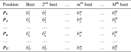
Two types of fingerprints are defined, and are characterized based on the storage method of the measurement data. The first type is the user-based fingerprint. This method adopts the conventional exhaustive-search-based beam sweeping, during which the base station periodically transmits reference signals (RSs) via each configured Tx beam. The user measures the reference signal received power (RSRP) and transmits the optimal beam index back, along with the UE position, to the base station. Although it is possible to store all the measurements of all the beams from each contributing user, it is unnecessary. Only the measurements of the top-M beams require to be stored. This is because most of the beams do not travel along any propagation path and have negligible RSRP. Therefore, there is no information gained in retaining the data of all the beams. An example of a user-based fingerprint is shown as in Tab. 1, where 
 is the
  th contributing user position and
 is the
  -th best beam of the
  th contributing user.
Table 1: Example of user-based fingerprint
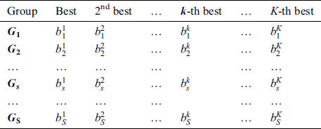
The group-based fingerprint is created from the user-based fingerprint. The measurement data are stored according to the best beam. This is because the direction of the beam or the number of beams available is highly dependent on the user’s position. The users are grouped according to the best beam. The number of groups is determined by the coverage of the base station. After grouping, all the beams, except for the best beam, are sorted for all the users in each group based on the RSRP. Finally, the fingerprint is constructed by resorting to a beam index of the order of the highest beam index for each group. An example of a group-based fingerprint is shown as in Tab. 2, where 
 is the
  -th group and
 is the
  -th best beam of the
  -th group. This example utilizes the top-K beams.
Table 2: Example of group-based fingerprint
3.2 Beam Selection for Interference Mitigation
Owing to the readily available nature of position information as a built-in feature (e.g., global positioning system or network positioning system) with an increasing degree of accuracy, it can be safely assuming that the user is aware of their current position and feeds this information back to the base station. The base station then matches the contributing user position fed back by the user with the fingerprint database. The contributing user positions in the fingerprint database are then matched sequentially. Matching refers to the action of identifying the best-matched fingerprint user position in the fingerprint database having the smallest error based on the current position of the user  ,
,

where  is the current position of the user
  ,
,  is the contributing user position
  , and
, and  is the best-matched fingerprint position. Consequently, a matched fingerprint position that is closest to the current position of the user can be obtained. The base station then matches the group according to the best-matched fingerprint position.
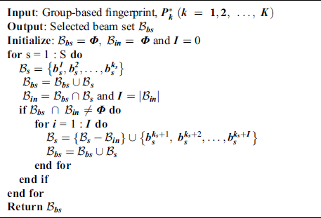
After the matching process, beam selection for interference mitigation is performed using the information contained in the group-based fingerprint database. Intra-group and inter-group interferences exist in beamspace multi-user MIMO communications. Therefore, the beams are selected considering both interferences. While the intra-cell interference is generated by beam sharing in the same group, inter-cell interference is generated by beam sharing in the different groups. First, the beams used to cancel the intra-group interference are selected. The number of users in  -th group
  is
is  and
and 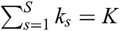 . From the group-based fingerprint database, the unshared beams for group
  are selected. The beam set for group
  is
is 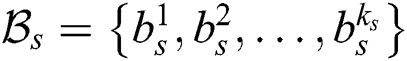 . The inter-group interference is then checked. If
  beams are already selected in the other group, the beams in the beam set are then deleted and replaced with the next beams,
  ,
,  in the fingerprint database. The process is reiterated until
  , where
  is interference beam set and
  is the cardinality of
  . Consequently, the intra-group and the inter-group interferences are cancelled. We summarize the proposed beam selection technique in Algorithm 1.
Algorithm 1: Proposed Beam Selection for Interference Mitigation
In this section, we evaluate the performance of the proposed fingerprint-based mmWave beam selection technique using realistic 3D ray-tracing simulations.
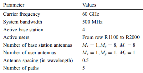
The simulation setup was based on the publicly available generic DeepMIMO [25] dataset, with the parameters listed as in Tab. 3. These parameters were obtained using the 3D ray-tracing software, Wireless InSite [26], which captured the channel dependence on the frequency. In particular, we considered base station 4 in the street-level outdoor scenario “O1,” communicating with the mobile users from row R1200 to R1500. The frequency of the mmWave was set at 60 GHz. Additionally, the base station was equipped with a UPA antenna array with  antennas. Each user was equipped with one antenna. The development of the system model is described in Section 2. The channel vector was constructed using parameters such as complex gain, azimuth angle, and elevation angle.
Table 3: DeepMIMO dataset parameters
The following schemes are simulated for comparison:
1.Fully digital BF system (Fully DBF). Here, every antenna corresponds to an RF chain, all the beams are used to send data, and no beam selection algorithm is utilized.
2.Random beam selection (Random BS). The beams are randomly selected from all the beams in the beamspace MIMO. Here, there is a likelihood that the same beam in the beamspace will be selected for different users.
3.User-based fingerprint beam selection (User-FP BS). The positions of the users are matched with a reference position in a user-based fingerprint database in order to perform beam selection. In the matching process, the best beam for each user is obtained and selected. Here, there is a likelihood that the same beam in the beamspace will be selected for different users.
4.Group-based fingerprint beam selection (Group-FP BS). The user’s positions are matched with the group in a group-based fingerprint database in order to perform beam selection. In the matching process, the beam set for each group is obtained. The beams are then selected to mitigate the intragroup and intergroup beam interferences.
The sum-rate of the beamspace MIMO precoder are assessed. Since the main focus is on the beam selection in the analog domain, a widely used zero-forcing precoder is utilized for the baseband and is given as 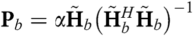 [27], where
  is a scaling factor to ensure
  and
and  is the transmit power of the base station, which is equal to the transmit signal-to-noise ratio (SNR) for
  . Thus, the factor
  is given as:

When an equal power allocation scheme is utilized at the base station, the average rate of the kth user is obtained as:

Then, the sum-rate is  in [bps/Hz].
Fig. 3 shows the sum-rate against SNR, where  is the number of users. We can observe that the proposed beam selection scheme (Group-FP BS) can achieve a higher sum-rate than random and user-FP BS schemes, where the sum-rate gaps are about 30 bps/Hz and 41 bps/Hz at SNR 10 dB, respectively. This is because the same beam will be selected for different users and the dimension-reduced beamspace channel matrix
  will be rank-deficient in the case of random and user-FP BS schemes. This indicates that some users cannot be served, leading to user unfairness and a significant performance loss in terms of the sum-rate. In contrast, the proposed beam selection scheme guarantee that all K users can be served simultaneously with a sum-rate close to that of a fully digital system. The dimension-reduced precoding matrix
  is able to closely approximate their fully digital precoding matrix
  .
.
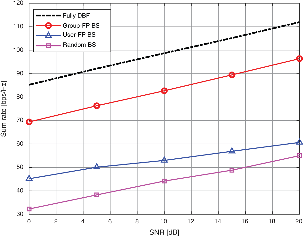
Figure 3: Sum rate against SNR, where the number of users is 
To evaluate the trade-off between the performance and RF complexity in practical implementation, the energy efficiency obtained using the different beam selection schemes are shown in terms of the number of RF chains required. The definition of energy efficiency used in [28] are applied as follows:

where  represents the sum rate in [bps/Hz],
  is the transmitted power of the system in [W], and
  is the power consumed in the components per RF chain in [W]. We use the practical values of
  mW (which accounts for the mixer, digital-to-analog converter, and filters) and
 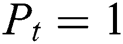 W (30 dBm). These metrics are particularly useful to show the effects of the selection of a decreased number of beams on the power required by the system, in addition to the effects on the average sum-rate of the system.
Fig. 4 shows the energy efficiency against SNR. We can observe that the proposed beam selection scheme (Group-FP BS) achieve a higher energy efficiency than to the random and user-FP BS schemes. In addition, it can achieve a much higher energy efficiency compared to the fully DBF scheme, where the number of RF chains is equal to the number of base station antennas, which leads to very high energy consumption. In contrast, in the proposed beam selection scheme, the number of RF chains is much smaller than the number of antennas. Therefore, the high energy consumption caused by the RF chains can be significantly reduced in comparison with that of the fully DBF scheme.
Figure 4: Energy efficiency against SNR, where the number of users is 
In summary, the proposed beam selection scheme can effectively select a beam, with low complexity. In addition, the proposed scheme can effectively mitigate the influence of beam interference and thus improve the performance of the system.
In this paper, a fingerprint-based mmWave beam selection technique consisting of offline and online phases was proposed by considering the potential multi-user interferences. In the offline phase, a user-group-based fingerprint database was constructed. In the online phase, the beam set for each group was obtained from the fingerprint database. Later, the beams were selected in order to eliminate the intragroup and intergroup beam interferences. The simulation results confirmed that the proposed beam selection scheme could achieve a sum-rate performance close to that of a fully digital system, albeit with a higher energy efficiency.
Funding Statement: This research was supported by the Ministry of Science and ICT (MSIT), Korea, under the Information Technology Research Center (ITRC) support program (IITP-2020-2016-0-00314) supervised by the Institute for Information & communications Technology Planning & Evaluation (IITP). and was supported by the National Research Foundation of Korea (NRF) grant funded by the Korea government (MSIT: Ministry of Science and ICT) (2018R1A2B6002255 and 2020R1I1A1A01073948).
Conflicts of Interest: The authors declare that they have no conflicts of interest to report regarding the present study.
References
1. Recommendation ITU-R. M.2083-0. IMT-Vision-Framework and Overall Objectives of the Future Development of IMT for 2020 and Beyond. 2015. [Online]. Available: https://www.itu.int/dms_pubrec/itu-r/rec/m/R-REC-M.2083-0-201509-I!!PDF-E.pdf.
2. J. G. Andrews, S. Buzzi, W. Choi, S. V. Hanly and A. Lozano. (2014). “What will 5G be?” IEEE Journal on Selected Areas in Communications, vol. 32, no. 6, pp. 1065–1082.
3. P. Li, Y. Gao, Z. Li and D. Yang. (2019). “Pilot sequence assignment for spatially correlated massive MIMO circumstances,” KSII Transactions on Internet and Information Systems, vol. 13, no. 1, pp. 237–253.
4. A. L. Swindlehurst, E. Ayanoglu, P. Heydari and F. Capolino. (2014). “Millimeter-wave massive MIMO: The next wireless revolution?,” IEEE Communications Magazine, vol. 52, no. 9, pp. 56–62.
5. H. Q. Ngo, E. G. Larsson and T. L. Marzetta. (2013). “Energy and spectral efficiency of very large multiuser MIMO systems,” IEEE Transactions on Communications, vol. 61, no. 4, pp. 1436–1449.
6. S. Rangan, T. S. Rappaport and E. Erkip. (2014). “Millimeter-wave cellular wireless networks: potentials and challenges,” Proceedings of the IEEE, vol. 102, no. 3, pp. 366–385.
7. Z. Pi, J. Choi and R. Heath. (2016). “Millimeter-wave gigabit broadband evolution towards 5G: Fixed access and backhaul,” IEEE Communications Magazine, vol. 54, no. 4, pp. 138–144.
8. S. Han, C. I., Z. Xu and C. Rowell. (2015). “Large-scale antenna systems with hybrid analog and digital beamforming for millimeter wave 5G,” IEEE Communications Magazine, vol. 53, no. 1, pp. 186–194.
9. W. Roh, J. Seol, J. Park, B. Lee, J. Lee et al.. (2014). , “Millimeter-wave beamforming as an enabling technology for 5G cellular communications: theoretical feasibility and prototype results,” IEEE Communications Magazine, vol. 52, no. 2, pp. 106–113.
10. Z. Pi and F. Khan. (2011). “An introduction to millimeter-wave mobile broadband systems,” IEEE Communications Magazine, vol. 49, no. 6, pp. 101–107.
11. A. Alkhateeb, G. Leus and R. W. Heath. (2015). “Limited feedback hybrid precoding for multi-user millimeter wave systems,” IEEE Transactions on Wireless Communications, vol. 14, no. 11, pp. 6481–6494.
12. A. Alkhateeb, O. El Ayach, G. Leus and R. W. Heath. (2014). “Channel estimation and hybrid precoding for millimeter wave cellular systems,” IEEE Journal of Selected Topics in Signal Processing, vol. 8, no. 5, pp. 831–846.
13. G. C. Alexandropoulos and S. Chouvardas. (2016). “Low complexity channel estimation for millimeter wave systems with hybrid A/D antenna processing,” in Proc. GC Wkshps, Washington, DC, USA, pp. 1–6.
14. G. C. Alexandropoulos. (2017). “Position aided beam alignment for millimeter wave backhaul systems with large phased arrays,” in Proc. CAMSAP, Curacao, Netherlands Antilles, pp. 1–5.
15. N. González-Prelcic, R. Méndez-Rial and R. W. Heath. (2016). “Radar aided mmwave beam alignment in V2I communications supporting antenna diversity,” in Proc. ITA, La Jolla, CA, USA, pp. 1–7.
16. Y. Han, H. Zhang, S. Jin, X. Li, R. Yu et al.. (2015). , “Investigation of transmission schemes for millimeter-wave massive MU-MIMO systems,” IEEE Systems Journal, vol. 11, no. 1, pp. 72–83.
17. A. Sayeed and J. Brady. (2013). “Beamspace MIMO for high-dimensional multiuser communication at millimeter-wave frequencies,” in Proc. GLOBECOM, Atlanta, GA, USA, pp. 3679–3684.
18. T. S. Rappaport, G. R. Maccartney, M. K. Samimi and S. Sun. (2015). “Wideband millimeter-wave propagation measurements and channel models for future wireless communication system design,” IEEE Transactions on Communications, vol. 63, no. 9, pp. 3029–3056.
19. X. Gao, L. Dai, S. Han, C. L. I and X. Wang. (2017). “Reliable beamspace channel estimation for millimeter-wave massive MIMO systems with lens antenna array,” IEEE Transactions on Wireless Communications, vol. 16, no. 9, pp. 6010–6021.
20. J. Wang, Z. Lan, C. Pyo, T. Baykas, C. Sum et al.. (2009). , “Beam codebook based beamforming protocol for multi-gbps millimeter-wave WPAN systems,” IEEE Journal on Selected Areas in Communications, vol. 27, no. 8, pp. 1390–1399.
21. S. Hur, T. Kim, D. Love, J. Krogmeier, T. Thomas et al.. (2013). , “Millimeter wave beamforming for wireless backhaul and access in small cell networks,” IEEE Transactions on Communications, vol. 61, no. 10, pp. 4391–4403.
22. B. D. S. Lakmali and D. Dias. (2008). “Database correlation for GSM location in outdoor & indoor environments,” in Proc. ICIAFS, Colombo, Sri Lanka, pp. 42–47.
23. E. Kupershtein, M. Wax and I. Cohen. (2013). “Single-site emitter localization via multipath fingerprinting,” IEEE Transactions on Signal Processing, vol. 61, no. 1, pp. 10–21.
24. H. Liu, S. Moon, H. Kim and I. Hwang. (2020). “Fingerprint-based interference-aware beam selection in beamspace millimeter-wave communications,” in Proc. APIC-IST, Seoul, Republic of Korea.
25. A. Alkhateeb. (2019). “DeepMIMO: A generic deep learning dataset for millimeter wave and massive MIMO applications,” in Proc. ITA, San Diego, CA, USA.
26. Remcom. (2018). Wireless Insite. [Online]. Available: http://www.remcom.com/wireless-insite.
27. X. Bian, J. Tian, H. Wang, M. Li and R. Song. (2020). “A simplified zero-forcing receiver for multi-user uplink systems based on CB-OSFB modulation,” KSII Transactions on Internet and Information Systems, vol. 14, no. 5, pp. 2275–2293.
28. X. Gao, L. Dai, S. Han, I. C. and R. W. Heath. (2016). “Energy-efficient hybrid analog and digital precoding for mmwave MIMO systems with large antenna arrays,” IEEE Journal on Selected Areas in Communications, vol. 34, no. 4, pp. 998–1009.
 | This work is licensed under a Creative Commons Attribution 4.0 International License, which permits unrestricted use, distribution, and reproduction in any medium, provided the original work is properly cited. |