DOI:10.32604/cmc.2021.013908
| Computers, Materials & Continua DOI:10.32604/cmc.2021.013908 | |
| Article |
Quintuple Band Antenna for Wireless Applications with Small Form Factor
1Department of Intelligent Mechatronics Engineering, Sejong University, Seoul, 05006, Korea
2Department of Telecommunication Engineering, University of Engineering and Technology, Taxila, 47050, Pakistan
3Department of Electrical Engineering, Polytechnique Montreal, Montreal, QC H3T 1J4, Canada
*Corresponding Author: Hyung Seok Kim. Email: hyungkim@sejong.ac.kr
Received: 28 August 2020; Accepted: 05 October 2020
Abstract: A coplanar waveguide-fed quintuple band antenna with a slotted circular-shaped radiator for wireless applications with a high isolation between adjacent bands is presented in this paper. The proposed antenna resonates at multiple frequencies with corresponding center frequencies of 2.35, 4.92, 5.75, 6.52, and 8.46 GHz. The intended functionality is achieved by introducing a circular disc radiator with five slots and a U-shaped slot in the feed. The proposed antenna exhibits coverage of the maximum set of wireless applications, such as satellite communication, worldwide interoperability for microwave access, wireless local area network (WLAN), long-distance radio telecommunications, and X-band/Satcom wireless applications. The simulation and measurement results of the proposed fabricated antenna demonstrate the high isolation between adjacent bands. A stable realized gain with an advantageous radiation pattern is achieved at the operating frequency bands. The proposed simple design, compact structure, and simple feeding technique make this antenna suitable for integration in several wireless communication applications, where the portability of devices is a significant concern. The proposed antenna is anticipated to be an appropriate candidate for WLAN, long-term evolution, and fifth-generation mobile communication because of its multi-operational bands and compact size for handheld devices.
Keywords: Coplanar waveguide; isolated adjacent bands; satellite; WiMAX; WLAN; 5G communication
In recent years, a prominent trend in antenna design is miniaturization including the reduction in the complications involved in the fabrication of such antennas while maintaining feed network connectivity. To achieve this, many designers have demonstrated a significant preference for multiband antennas over conventional ones with a single band. The multiband functionalities can be added to standard microstrip antennas by introducing specific alterations in the antenna geometry, such as creating slots of various shapes and cutting patches of different sizes. Various multiband design approaches have been reported in the literature. Among these are modifying the main radiating element of the antenna by integrating a metamaterial-based split ring resonator [1] and slot insertion [2]; multiple frequency bands are also achieved through the use of defective ground planes [3]. However, the main deficiency of the foregoing changes in conventional microstrip antennas is that these modifications tend to limit the antenna to a narrow operational bandwidth.
To overcome this bandwidth limitation, the monopole antenna, with its wide operational bandwidth, has emerged as the primary alternative because of its simple design, facile fabrication, light weight, compact geometry, and significant efficiency compared with conventional antennas. To achieve high data transmission and reception, the monopole antenna may be incorporated into various portable communication devices. In Karim et al. [4], several types of multiband antennas that can satisfy the abovementioned requisites are identified. In a wireless communication system utilizing such antennas, designing a small-sized multiband antenna while maintaining adequate isolation among all operating bands is crucial. Moreover, coplanar waveguide (CPW)-fed antennas have gained considerable acceptance in several applications because they afford further advantages, such as facile integration, simple structured metallic layer, and lesser coupling [5].
To achieve the characteristic performance of multi-functional transceivers, simultaneous multiband antenna operations are required. Two types of antennas are usually considered: multiband and reconfigurable antennas. For various applications where more than one operating band is necessary, multiple antennas may be used to achieve a better device performance. This may be gained at the cost of complexity and coupling as a result of the diminutive antenna space occupied. For combining multiple applications, a multiband antenna can satisfy certain requisites, such as high efficiency, low cost, and miniaturized circuit size while maintaining the necessary transmission parameters including various operating bands with acceptable gains and wide bandwidths. Currently, few techniques for the development of multiband antennas include the insertion of slots and addition of metamaterial-based structures inside radiating elements. Multiple frequency bands can also be achieved using defective ground structures, fractal geometry, split-ring resonators, etc. [6–9].
Complementary split-ring resonator-based multiple band achievement has been formulated and verified in Rahman et al. [6] via the distribution and lumped model. It has been demonstrated that a wideband antenna can be designed using a cylindrical radiator and can be switched to multiple bands using integrating capacitors. One of the significant benefits of ultra-wideband antennas is that they include the operating bands of commercial applications, such as wireless local area network (WLAN) and worldwide interoperability for microwave access (WiMAX); however, there exists a tradeoff between the multiband operation of desired applications and the risk of interplay with other working bands [7]. Ahmad et al. [8] presented the smallest form factor multiband antenna for WLAN and WiMAX applications with the corresponding sophisticated shape and simple geometry. A triple-band microstrip patch antenna with a complex geometric structure and large overall size for WLAN/WiMAX applications is reported in Gautam et al. [9]. A similar type of antenna with multiple bands for wideband applications is also presented in [10–12]. In Haider et al. [10], an antenna with the capability of switching between the wideband and narrowband behaviors while being utilized for microwave breast imaging application was designed. Moreover, in Rahman et al. [11], a wideband antenna with a corresponding equivalent circuit and its transformation to different wireless band applications utilizing the Babinet principle is designed. In Rahman et al. [12], similar techniques have been adopted, and a wideband antenna having five notch bands with corresponding distributed and equivalent models has been achieved.
Recently, certain antennas have been designed for dual-band applications and simultaneously integrated to operate at long-term evolution (LTE) and 5G communication. In this regard, Chen et al. [13] developed a microstrip patch antenna operating at 28 GHz with a corresponding impedance bandwidth of approximately 26%. The antenna is capable of operating at a single band for 5G applications. Similarly, in Naqvi et al. [14], an integrated multiple-input multiple-output antenna operating at 5.29–6.12 GHz and 26–29.5 GHz for the corresponding LTE and millimeter wave applications was designed, respectively.
The design of quadruple and pentaband antennas has also gained considerable interest. In this regard, a quad-rectangular shaped microstrip antenna operating at frequencies of 1.074, 3.119, 4.089, 5.683, and 6.514 GHz is presented in Saroj et al. [15]. Moreover, in Ali et al. [16], a novel quad-band antenna operating at the global navigation satellite system, lower WiMAX, upper WLAN, and X-band for satellite communication using FR4 material is developed. A metamaterial-based hepta-band antenna with a reduced specific absorption rate is presented in Saraswat et al. [17]. The proposed structure possesses the capability of simultaneously operating at WLAN (2.4, 5.0, and 5.8 GHz), radio frequency identification (3 GHz), WiMAX (3.5 GHz), and lower Ku band. Similarly, a triple band antenna couple set-fed rectangular-shaped antenna with corresponding M-shaped branches for wireless appliances was developed in Naidu et al. [18]. Moreover, Albawri et al. [19] attempted to enhance the gain and radiation pattern of the quadruple band metamaterial-based antenna for wireless communication. A low-profile horizontal patch stacked antenna with corresponding corner feeding for pentaband wireless applications is presented in Singh et al. [20]. In Park et al. [21], the authors successfully demonstrated a novel technique to reduce mutual coupling between two closely packed antennas.
This paper presents a coplanar waveguide-fed quintuple band antenna with a slotted circular-shaped radiator for wireless applications. The proposed structure has the capability of high isolation between adjacent frequency bands. It simultaneously resonates at multiple frequencies with corresponding center frequencies at 2.35, 4.92, 5.75, 6.52, and 8.46 GHz. The presented structure is demonstrated and formulated with a corresponding validation in the finite element method solver Ansoft high-frequency structure simulator (HFSS). For the utilization of the antenna in practical scenarios, it is also fabricated, and its results are measured. The vector network analyzer (VNA) is used for S-parameter measurement, and the radiation patterns and antenna gain are obtained from anechoic chamber measurements. The simulated results are compared with the corresponding measurements in each scenario.
The rest of this manuscript is organized as follows. Section 2 presents the antenna design and configuration, mainly focusing on antenna development and geometrical dimension selection. Moreover, the step-by-step design methodology is briefly discussed in this section. The simulation and measurement results for the proposed antenna design, such as antenna gain, reflection coefficient, radiation patterns, and surface current distributions, are elaborated in Section 3. The comparison between the proposed quintuple band antenna with other recent state-of-the-art designs is presented in Section 4 to demonstrate the superiority of the former. Section 5 summarizes the conclusion of the study.
The geometric configuration of the proposed quintuple band antenna is shown in Fig. 1a. Its design is implemented on the 1.6 mm thick FR4 substrate. The dielectric constant value and loss tangent are 4.4 and 0.02, respectively; the overall size of the antenna is 40 × 60 mm2. Its primary structure is a circular disk that is designed to resonate on a single frequency band, i.e., WiMAX band, according to Eqs. (1) and (2):

Figure 1: Proposed quintuple band antenna configuration: (a) Dimensional diagram; (b) Fabricated prototype


where  ;
;  is the effective radius; t is the substrate thickness; a is the actual radius.
The fabricated prototype of the proposed antenna is shown in Fig. 1b. To verify its performance characteristics, the proposed antenna is fabricated according to the prototype antenna. The VNA is utilized to measure its corresponding reflection coefficient. A through-reflect-line calibration is performed before the measurement to avoid undesirable losses. For the radiation pattern, the VNA along with two horn antennas are employed to obtain the measurements in the anechoic chamber environment. This chamber can detect antennas in the frequency range 0.8–30 GHz. It is equipped with a near-field planner scanner and far-field tower to measure the radiation pattern of a given antenna under test. To overcome the effects of fabrication disparity, the measured results are validated by testing five different prototypes of the proposed antenna; the prototype whose results agree with the simulated results is selected.
The actual radius (a = 24 mm) is calculated using Eqs. (1) and (2); this radius results in the resonation of the antenna at the lowest operating frequency (2.4 GHz) in the first step (antenna a). In the second step (antenna b), with the insertion of three slots perpendicular to each other, three operating frequencies are achieved for the proposed antenna: 2.45, 4.9, and 6.1 GHz; consequently, the radius of the circular disc can be reduced to 14 mm. In the third step, two more slots are inserted into the lower portion of the circular disc, which results in the inclusion of another frequency band (8.4 GHz) along with the previous three resonating bands (antenna c). The final design (antenna d) is realized by introducing a U-shaped slot in the feedline. Through this approach, the resulting antenna structure starts to resonate at an additional frequency band (i.e., 6.52 GHz), as shown in Fig. 2. Furthermore, this newly introduced slot in the feedline only slightly influences the existing bands.

Figure 2: Representation of reflection coefficient employed at different stages of proposed quintuple band antenna
To excite the proposed antenna, a 1-mm wide CPW feedline is used with a characteristic impedance of 50 Ω. The CPW feedline value is estimated by employing Eqs. (3)–(8) [15].


where Sc is the width of the central conductor; W is the separation distance between the ground plane and central conductor; h and εr denote the substrate thickness and relative dielectric constant used for the proposed antenna, respectively; εeff denotes the effective dielectric constant; K(k) represents a first-order integral having an argument (k) or complementary argument (k΄). To achieve a wide operation bandwidth, improve efficiency, and afford ease in integration, a CPW-fed ground plane is employed.
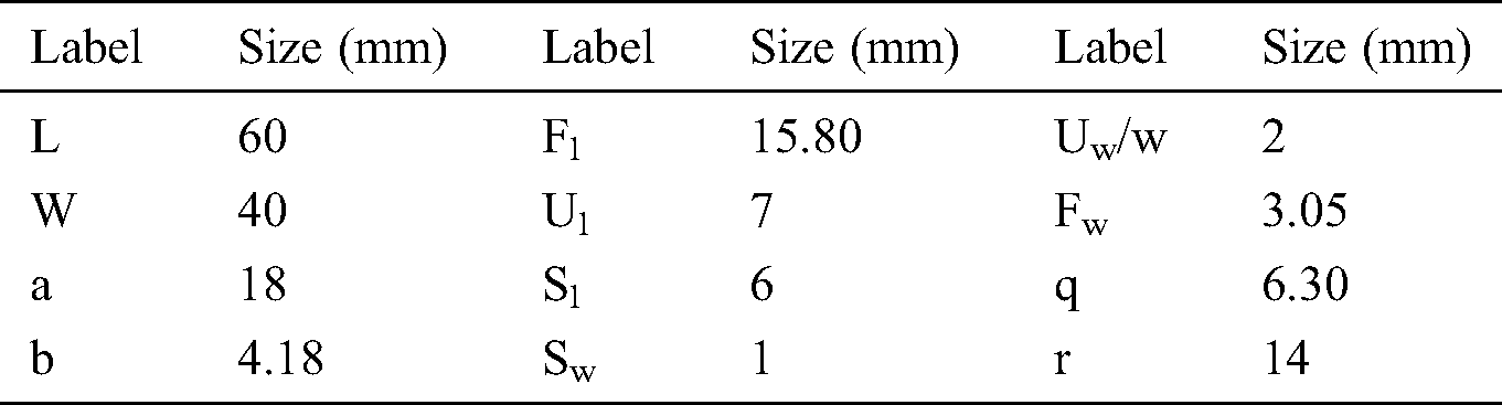
The inclusion of slots variates the current distributions, causing them to radiate at other frequencies. Accordingly, the slots are inserted, thus creating multiple passbands. As depicted in Fig. 2, the introduction of the slots in the radiator creates passbands at 6.52 and 8.46 GHz. Without a slot, this triple band antenna can only resonate near the fundamental frequency, i.e., 2.35 GHz. Moreover, the symmetrical insertion of the slots eliminates the distortion in the radiation pattern. The design of the proposed antenna is further optimized by employing a high-frequency structure simulator (ANSYS HFSS). Tab. 1 summarizes the parameters of the resultant antenna.
Table 1: Optimal parameters for proposed antenna
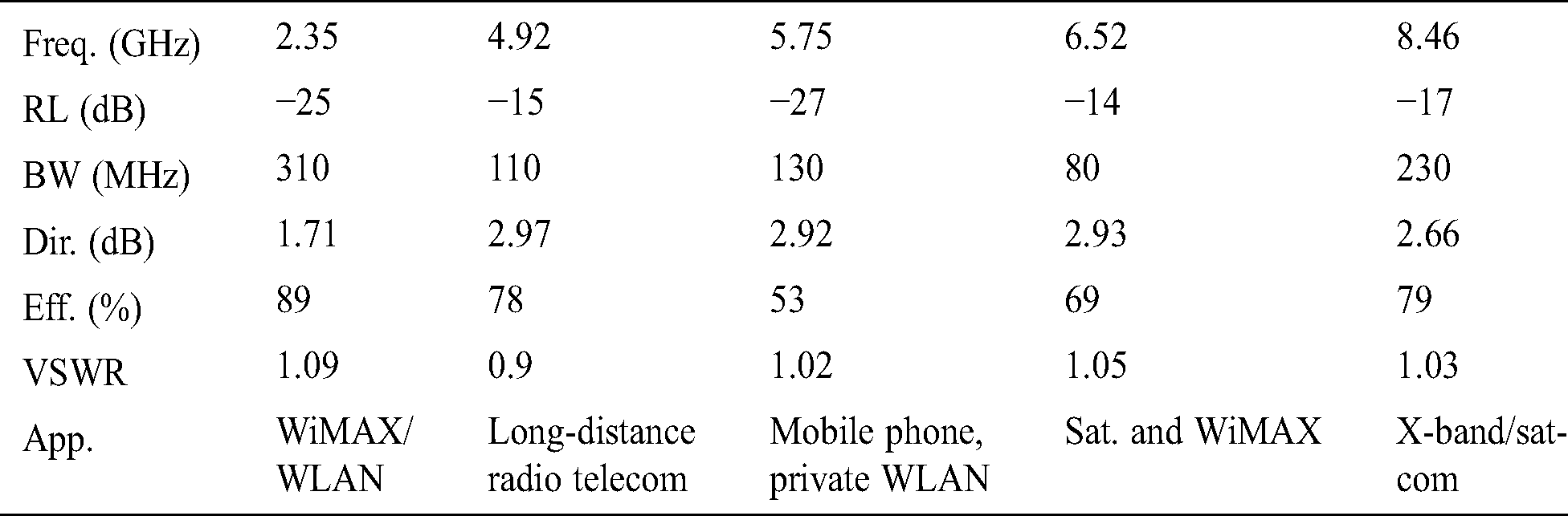
The proposed quintuple band antenna resonates at a frequency band range of 2.20–8.57 GHz. For the first band of operation, from 2.20 to 2.51 GHz, the central frequency is 2.35 GHz with an impedance bandwidth of 310 MHz. The first frequency band of the proposed antenna covers the 2.4 GHz and 2.5 GHz WLAN and WiMAX bands, respectively. The second band starts at 4.89 GHz and ends at 5.00 GHz with a central frequency of 4.92 GHz and an impedance bandwidth of 110 MHz. This band is utilized for long-distance radio telecommunications. The third band has an impedance bandwidth of 130 MHz, from 5.68 to 5.81 GHz, with a central frequency of 5.75 GHz. It may be used in mobile phones and commercial wireless LAN. The fourth band starts from 6.48 to 6.56 GHz with an impedance bandwidth of 80 MHz and a central frequency of 6.52 GHz. This band supports fixed satellite communication and WiMAX applications. The last band starts from 8.34 to 8.57 GHz with an impedance bandwidth of 230 MHz and a central frequency of 8.46 GHz. It covers a useful part of X-band/Satcom wireless applications. The comparison between the measured and simulated S11 values of the proposed quintuple band antenna is shown in Fig. 3. The corresponding simulated and measured responses are in good agreement; considering the fabrication error and various influencing factors, the inconsistencies between the measured and simulated results are reasonable.

Figure 3: Comparison between measured and simulated S11 values of proposed quintuple band antenna
The surface current distributions at the resonance frequencies of the proposed quintuple band antenna at 2.35, 4.92, 5.75, 6.52, and 8.46 GHz are shown in Figs. 4a–4e, respectively. It is observed from the current distribution plots that the proposed antenna radiates well at all passbands. The proposed antenna in the anechoic chamber where its radiation pattern is measured is shown in Fig. 5. The measured and simulated radiation patterns of the proposed quintuple band antenna at 2.3, 4.9, and 5.75 GHz are shown in Fig. 6. This figure shows that the presented antenna design has a virtually dipole-like radiation pattern in the XZ-plane and omnidirectional radiation patterns in the YZ-plane at all frequency bands of interest.

Figure 4: Surface current distributions of proposed quintuple band antenna at (a) 2.35, (b) 4.92, (c) 5.75, (d) 6.52, and (e) 8.46 GHz

Figure 5: Proposed quintuple band antenna in anechoic chamber for measurement

Figure 6: Measured and simulated radiation patterns of proposed quintuple band antenna at 2.3, 4.9, and 5.75 GHz
The average gains of the proposed quintuple band antenna are 1.53, 2.35, 1.57, 1.40, and 2.12 dBi at 2.35, 4.92, 5.75, 6.52, and 8.46 GHz, respectively. The realized gain is virtually constant in all passbands with a variation of <2 dBi. Hence, the proposed quintuple band antenna exhibits stable gains across all working bands being an essential parameter in practical wireless applications.
The simulated realized gain (dBi) of the proposed antenna at different operating resonance frequencies is illustrated in Fig. 7. A satisfactory gain is observed at the center of each passband as well as on the corresponding right and left operating edges of the passbands. As a result, any shift in the design parameter will still maintain the realized gain within an appropriate range. Tab. 2 summarizes the results of all the operating frequency bands of the proposed quintuple band antenna.

Figure 7: Simulated gain (dBi) of proposed quintuple band antenna at resonance frequencies
Table 2: Summarized results of the proposed quintuple band antenna
4 Comparison of Proposed Antenna with Other State-of-the-Art Designs
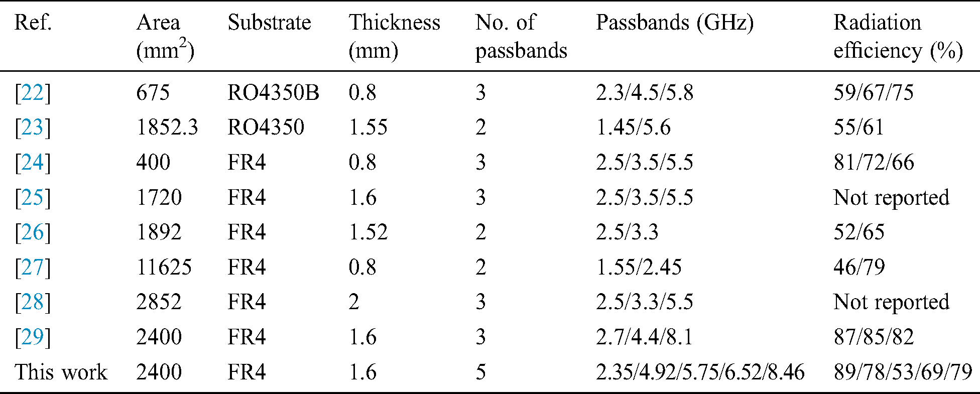
This section presents a detailed comparison of the fabrication parameters and performance between the proposed antenna and recent state-of-the-art designs. This elaborate comparison highlights the novelty of this work. Tab. 3 summarizes the detailed comparison where certain parameters are set for defining the features of the antenna. The proposed antenna is observed to be advantageous in terms of maximum passbands, low-cost substrate, and overall size.
Table 3: Summarized results of the proposed quintuple band antenna
A coplanar waveguide-fed quintuple band antenna with a slotted circular-shaped radiator for wireless applications with a high isolation between adjacent bands is presented. The proposed antenna is designed, simulated, fabricated, and measured. The antenna resonates at five different frequency bands, and this is attributed to the inclusion of slots and the antenna’s simple structure. The simulated and measured results of the proposed fabricated antenna exhibit a high isolation between adjacent bands. The stable realized gain with an advantageous radiation pattern is also achieved at the operating frequency bands. The proposed antenna is anticipated to be a suitable candidate for wireless and mobile communication systems.
Funding Statement: This work was supported by the National Research Foundation of Korea (NRF) grant funded by the Korean government (MSIT) (No. 2019R1A4A1023746, No. 2019R1F1A1060799) and Strengthening R&D Capability Program of Sejong University.
Conflicts of Interest: The authors declare that they have no conflicts of interest to report regarding the present study.
1. V. Rajeshkumar and S. Raghavan. (2015). “A compact metamaterial inspired triple band antenna for reconfigurable WLAN/WiMAX applications,” AEU-International Journal of Electronics and Communications, vol. 69, no. 1, pp. 274–280. [Google Scholar]
2. M. Rahman, M. NagshvarianJahromi, S. S. Mirjavadi and A. M. Hamouda. (2019). “Compact UWB band-notched antenna with integrated Bluetooth for personal wireless communication and UWB applications,” Electronics, vol. 8, pp. 158. [Google Scholar]
3. A. K. Gautam, A. Bisht and B. K. Kanaujia. (2016). “A wideband antenna with defected ground plane for WLAN/WiMAX applications,” AEU-International Journal of Electronics and Communications, vol. 69, no. 1, pp. 354–358. [Google Scholar]
4. M. F. Karim and A. Alphones. (2016). “A low-profile dual band circularly polarized GPS antenna,” in Proc. IEEE APMC, New Delhi, India, pp. 1–4. [Google Scholar]
5. R. Z. Wu, P. Wang, Q. Zheng and R. P. Li. (2015). “Compact CPW-fed triple-band antenna for diversity applications,” Electronics Letters, vol. 51, no. 10, pp. 735–736. [Google Scholar]
6. M. Rahman, D. S. Ko and J. D. Park. (2017). “A compact multiple notched ultra-wide band antenna with an analysis of the CSRR-TO-CSRR coupling for portable UWB applications,” Sensors, vol. 17, no. 10, pp. 2174. [Google Scholar]
7. M. Rahman, A. Haider and M. Naghshvarianjahromi. (2020). “A systematic methodology for the time-domain ringing reduction in UWB band-notched antennas,” IEEE Antennas and Wireless Propagation Letters, vol. 19, no. 3, pp. 482–486. [Google Scholar]
8. H. Ahmad, W. Zaman, M. Rahman and F. C. Seman. (2020). “The smallest form factor monopole antenna with meandered radiator for WLAN and WiMAX applications,” IETE Journal of Research, vol. 8, no. 2, pp. 1–9. [Google Scholar]
9. A. K. Gautam, L. Kumar, B. K. Kanaujia and K. Rambabu. (2016). “Design of compact F-shaped slot tripleband antenna for WLAN/WiMAX applications,” IEEE Transactions on Antennas and Propagation, vol. 64, no. 3, pp. 1101–1105. [Google Scholar]
10. A. Haider, M. Rahman, M. Naghshvarianjahromi and H. S. Kim. (2020). “Time-domain investigation of switchable filter wide-band antenna for microwave breast imaging,” Sensors, vol. 20, no. 15, pp. 4302. [Google Scholar]
11. M. Rahman, M. Naghshvarianjahromi, S. S. Mirjavadi and A. M. Hamouda. (2017). “Resonator based switching technique between ultra wide band (UWB) and single/dual continuously tunable-notch behaviors in UWB radar for wireless vital signs monitoring,” Sensors, vol. 18, no. 10, pp. 3330. [Google Scholar]
12. M. Rahman, W. T. Khan and M. Imran. (2018). “Penta-notched UWB antenna with sharp frequency edge selectivity using combination of SRR, CSRR, and DGS,” AEU-International Journal of Electronics and Communications, vol. 93, pp. 116–122. [Google Scholar]
13. T. Chen, Y. Chen, R. Jian, Z. Liu and A. Yang. (2019). “A novel broadband microstrip antenna based on operation of multi-resonant modes,” Computers, Materials & Continua, vol. 60, no. 1, pp. 335–349. [Google Scholar]
14. S. I. Naqvi, N. Hussain, A. Iqbal, M. Rahman, M. Forsat et al. (2020). , “Integrated LTE and millimeter-wave 5G MIMO antenna system for 4G/5G wireless terminals,” Sensors, vol. 20, no. 14, pp. 3926–3946. [Google Scholar]
15. A. K. Saroj, M. G. Siddiqui, M. Kumar and J. A. Ansari. (2017). “Design of multiband quad-rectangular shaped microstrip antenna for wireless applications,” Progress In Electromagnetics Research, vol. 59, pp. 213–221. [Google Scholar]
16. T. Ali, M. M. Khaleeq and R. C. Biradar. (2018). “A multiband reconfigurable slot antenna for wireless applications,” AEU-International Journal of Electronics and Communications, vol. 84, pp. 273–280. [Google Scholar]
17. R. K. Saraswat and M. Kumar. (2019). “A metamaterial hepta-band antenna for wireless applications with specific absorption rate reduction,” International Journal of RF and Microwave Computer-Aided Engineering, vol. 29, no. 10, pp. 1–12. [Google Scholar]
18. P. V. Naidu and A. Kumar. (2017). “Design and development of triple band ACS fed antenna with M and rectangular shaped radiating branches for 2.45/5 GHz wireless applications,” Microsystem Technologies, vol. 23, no. 12, pp. 5841–5848. [Google Scholar]
19. S. S. Albawri, M. S. Islam, H. Y. Wong, M. F. Jamlos, A. Narbudowicz et al. (2020). , “Metamaterial cell-based superstrate towards bandwidth and gain enhancement of quad-band CPW-fed antenna for wireless applications,” Sensors, vol. 20, no. 2, pp. 1–14. [Google Scholar]
20. J. Singh, R. Stephan and M. A. Hein. (2019). “Low-profile penta-band automotive patch antenna using horizontal stacking and corner feeding,” IEEE Access, vol. 7, pp. 74198–74205. [Google Scholar]
21. J. D. Park, M. Rahman and H. N. Chen. (2019). “Isolation enhancement of wide-band MIMO array antennas utilizing resistive loading,” IEEE Access, vol. 7, pp. 81020–81026. [Google Scholar]
22. L. Han, C. Wang, X. Chen and W. Zhang. (2016). “Compact frequency reconfigurable slot antenna for wireless applications,” IEEE Antennas and Wireless Propagation Letters, vol. 15, pp. 1795–1798. [Google Scholar]
23. M. A. Madi, M. A. Husseini and K. Y. Kabalan. (2018). “Frequency tunable cedar-shaped antenna for WiFi and WiMAX,” Progress In Electromagnetics Research Letters, vol. 72, pp. 135–143. [Google Scholar]
24. H. Ahmad, W. Zaman, S. Bashir and M. Rahman. (2019). “Compact triband slotted printed monopole antenna for WLAN and WiMAX applications,” International Journal of RF and Microwave Computer-Aided Engineering, vol. 30, no. 1, pp. 1–8. [Google Scholar]
25. X. Liu, X. Yang and F. Kong. (2015). “A frequency-reconfigurable monopole antenna with switchable stubbed ground structure,” Radioengineering, vol. 24, no. 2, pp. 449–454. [Google Scholar]
26. H. A. Majid, M. K. A. Rahim, M. R. Hamid and M. F. Ismail. (2012). “A compact frequency-reconfigurable narrowband microstrip slot antenna,” IEEE Antennas and Wireless Propagation Letters, vol. 11, pp. 616–619. [Google Scholar]
27. Z. Xu, C. Ding, Q. Zhou, Y. Sun and S. Huang. (2019). “Dual-band dual-antenna system with common-metal rim for smartphone applications,” Electronics, vol. 8, no. 3, pp. 348–357. [Google Scholar]
28. H. I. Azeez, H. C. Yang and W. S. Chen. (2019). “Wearable triband E-shaped dipole antenna with low SAR for IoT applications,” Electronics, vol. 8, no. 6, pp. 665–678. [Google Scholar]
29. T. Khan, M. Rahman, A. Akram, Y. Amin and H. Tenhunen. (2019). “A low-cost CPW-fed multiband frequency reconfigurable antenna for wireless applications,” Electronics, vol. 8, no. 8, pp. 900–917. [Google Scholar]
 | This work is licensed under a Creative Commons Attribution 4.0 International License, which permits unrestricted use, distribution, and reproduction in any medium, provided the original work is properly cited. |