DOI:10.32604/cmc.2021.015066
| Computers, Materials & Continua DOI:10.32604/cmc.2021.015066 | |
| Article |
A Novel Broadband Antenna Design for 5G Applications
Deparment of Electrical Engineering, Engineering Faculty, The Hashemite University, Zarqa, 13133, Jordan
*Corresponding Author: Omar A. Saraereh. Email: eloas2@hu.edu.jo
Received: 05 November 2020; Accepted: 01 December 2020
Abstract: Wireless communication is one of the rapidly-growing fields of the communication industry. This continuous growth motivates the antenna community to design new radiating structures to meet the needs of the market. The 5G wireless communication has received a lot of attention from both academia and industry and significant efforts have been made to improve different aspects, such as data rate, latency, mobility, reliability and QoS. Antenna design has received renewed attention in the last decade due to its potential applications in 5G, IoT, mmWave, and massive MIMO. This paper proposes a novel design of broadband antenna for 5G mmWave and optical communication networks. It is a hybrid structure that works for both spectrums and contains an absorption dielectric material with an electrical large size. A hybrid transmission line theory ray-tracing technique is proposed efficient and rapid simulation and optimization of the proposed antenna design. The operating frequency and wavelength of the proposed antenna are 28 GHz in the mmWave band and 1550 nm for the optical spectrum. The spatial frequency is 30 lp/mm when the contrast transfer function is reduced to 0.7 for the optical signal. The effective focal length and aperture are 816.86 and 200 mm. The half-power beamwidth is  and the gain is 32.97 dBi for the mmWave band. Simulation results show that the proposed hybrid antenna can effectively be deployed simultaneously for both optical and mmWave 5G communication networks.
Keywords: Antenna; mmwave; broadband; composite waveguide; wireless communication
High speed and large capacity are the development needs of next-generation communications. Free space optical communication has a high transmission rate (Gbit/s), large capacity, and good confidentiality [1]. It is one of the most promising communication methods. However, free-space optical communication is susceptible to the influence of the atmosphere [2], under heavy fog Its loss is as high as 100 dB/km, which can lead to an increase in communication error rate or communication interruption, and a decrease in reliability [3–5]. Although the transmission rate of millimeter-wave communication is not as high as that of free-space optical communication, it is suitable for all-weather work and has high reliability [6]. The mmWave and optical composite communication is a method that can effectively combine the advantages of both spectrums [7–9]. The mmWave and optical composite communication are considered to be an effective solution for the point-to-point terrestrial link in 5G networks due to the advantages of high speed and large capacity [10–12]. For example, it can provide a communication rate of Gbit/s for 5G backhaul, and can perform large-capacity data transmission and storage at a rate of the order of kilometers per hour, which greatly reduces the transmission cost of big data. Also, it can be used for delay-sensitive packet data transmission between high-altitude platform stations [13].
As early as 2004, the Advanced Research Projects Agency of the U.S. Department of Defense began to try to combine space optical communication and radio frequency communication into one network and launched the free-space optical and radio frequency combined link experimental project [14]. How to realize the common-aperture composite of mmWave and optical communication is one of the key technologies of interest. At present, only [15,16] have designed a common-aperture transceiver dual-purpose composite antenna for communication. The composite antenna realizes the common-aperture transmission and reception of optical signals and radio frequency signals, but its structure is complicated, the size is too large (the diameter of the main mirror is 475 mm), the effective aperture is small (the diameter is 85 mm), and the optical energy utilization rate is low. A Cassegrain structure antenna is designed, which can realize the co-aperture composite of millimeter-wave and optical bands. Compared with Northumbria University’s composite antenna (millimeter wave gain 27.52 dBi), the millimeter-wave gain in this antenna is higher, the effective aperture is large, it can receive more light energy, and the optical antenna gain is higher. The optical part of the antenna adopts the form of a Cassegrain optical telescope, so it can greatly compress the beam divergence angle and achieve high optical gain, which is conducive to space transmission [16].
The authors in [15–17] used the commercial software CST to calculate and simulate the radiation characteristics of the composite antenna, but this method consumes time and memory and is not conducive to the optimization and simulation of electrically large antennas. The authors in [18] used geometric optics to optimize the design of a composite antenna common aperture target simulator with a similar structure but ignored the influence of the lossy medium on radiation characteristics. The size of the common-aperture of the composite antenna is electrically large. Even if the multi-layer fast multipole acceleration algorithm (MLFMM) is used to simulate a single entity model, it will consume a lot of memory and time. If the structure is to be optimized, then large memory and time are needed, so it is necessary to find a fast calculation and efficient design method for the millimeter-wave radiation characteristics of the composite antenna.
To this end, this paper proposes a transmission line G-ray tracing hybrid algorithm, using geometric optics method to trace millimeter-wave rays, and at the same time, the antenna medium area is equivalent to a transmission line, which not only guarantees the calculation rate but also analyzes the influence of the composite antenna medium parameters on the radiation characteristics. This article uses the proposed method. The algorithm obtained the optimal parameters of the FSO/MMW composite antenna and accurately calculated its millimeter-wave performance.
2.1 FSO/MMW Cassegrain Structure
The Cassegrain structure can be applied to optical/radio frequency dual-mode guidance device to realize the common-aperture composite of two working band signals. The Cassegrain structure can make full use of its aperture to composite optical signals and millimeter-wave signals, and the optical axis and electrical axis of the composite signal coincide. Also, the optics and millimeter waves in the system share the same aperture, with simple structure, small size, low quality and low cost. Because the antennas are reciprocal in transmission and reception, the system can be used not only as a transmitting antenna but also as a receiving antenna. The following only discusses its design as a transmitting antenna, and this method is also suitable for composite receiving antenna design.
The working principle of the free-space optical signal/millimeter-wave signal common-aperture composite antenna is shown in Fig. 1. The composite antenna structure includes three parts: millimeter-wave feed or millimeter-wave detector, free space light/millimeter-wave composite device, optical feed (including correction lens) or optical detector. At the transmitting end, the dielectric dichroic mirror transmits the millimeter-wave signal and reflects the optical signal, and the mixed signal is reflected by the parabolic mirror and output by the common aperture. At the receiving end, the mixed-signal propagation direction is opposite to that of the transmitting end and is separated by the dichroic mirror and received by the millimeter-wave detector and the optical detector respectively. Among them, the FSO/MMW composite device includes a dielectric dichroic mirror and a parabolic mirror. A device is shared between free-space optical signals and millimeter-wave signals. Free space optical signal and millimeter-wave signal pass-through beam composite device to achieve co-caliber synthesis.
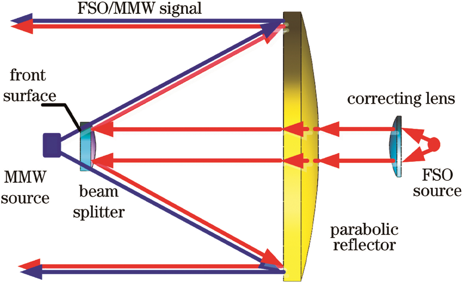
Figure 1: Operation of hybrid mm-wave/optical antenna
The design of hybrid mmWave/optical antennas is divided into two parts: optical system design and millimeter-wave antenna design. These two parts are related to each other and need to be considered comprehensively during design. Because the optical signal wavelength is shorter and the requirements for the composite structure are high, the optical structure is first designed, and the millimeter-wave antenna structure is optimized after the optical structure meets the requirements. Since the millimeter-wave signal and the optical signal share the front surface of the parabolic mirror and the dichroic mirror, their size and surface shape are temporarily fixed after the optical structure design is completed, and no adjustment is made in the millimeter-wave structure design unless the millimeter-wave indicator cannot satisfy, the optical structure is redesigned and adjusted. After the optical structure design is fixed, according to the millimeter-wave transmittance requirements of the dichroic mirror, the structural parameters of the dichroic mirror are determined based on the proposed hybrid transmission line and ray-tracing theory, to determine the structure of the composite antenna. The commercial software FEKO is used to analyze and calculate its millimeter-wave properties. If the millimeter-wave design requirements are not met, the optical structure is redesigned and adjusted until the optical indicators and millimeter-wave indicators meet the requirements.
The goal of a hybrid antenna design is to achieve a common-aperture synthesis of free-space light and millimeter-wave signals. At the same time, both optical signals and millimeter-wave signals have high gain and small divergence angles to ensure strong signal transmission capabilities and Long transmission distance. It can be seen from Fig. 1 that the millimeter wave transmitting antenna will pass through the dielectric dichroic mirror, which will cause the attenuation of the millimeter-wave signal. The dielectric dichroic mirror is realized by coating an optical high reflective film on a dielectric material High reflectivity reflection of the laser signal. The film system uses non-metallic materials to reduce the attenuation of millimeter-wave signals. Considering that the dielectric dichroic mirror is a lossy medium, a hybrid algorithm is proposed that combines transmission line theory and ray tracing to analyze the attenuation of the millimeter-wave signal by the lens. Fig. 2 shows the proposed TLTG-RTM model: Millimeter-wave ray tracing to the observation surface, during the tracing process, the dielectric dichroic mirror is regarded as a lossy transmission line, thereby obtaining the electric field distribution on the observation surface. Because the antenna is a rotationally symmetric structure, it can be traced in three-dimensional space Simplified to two-dimensional space tracing.
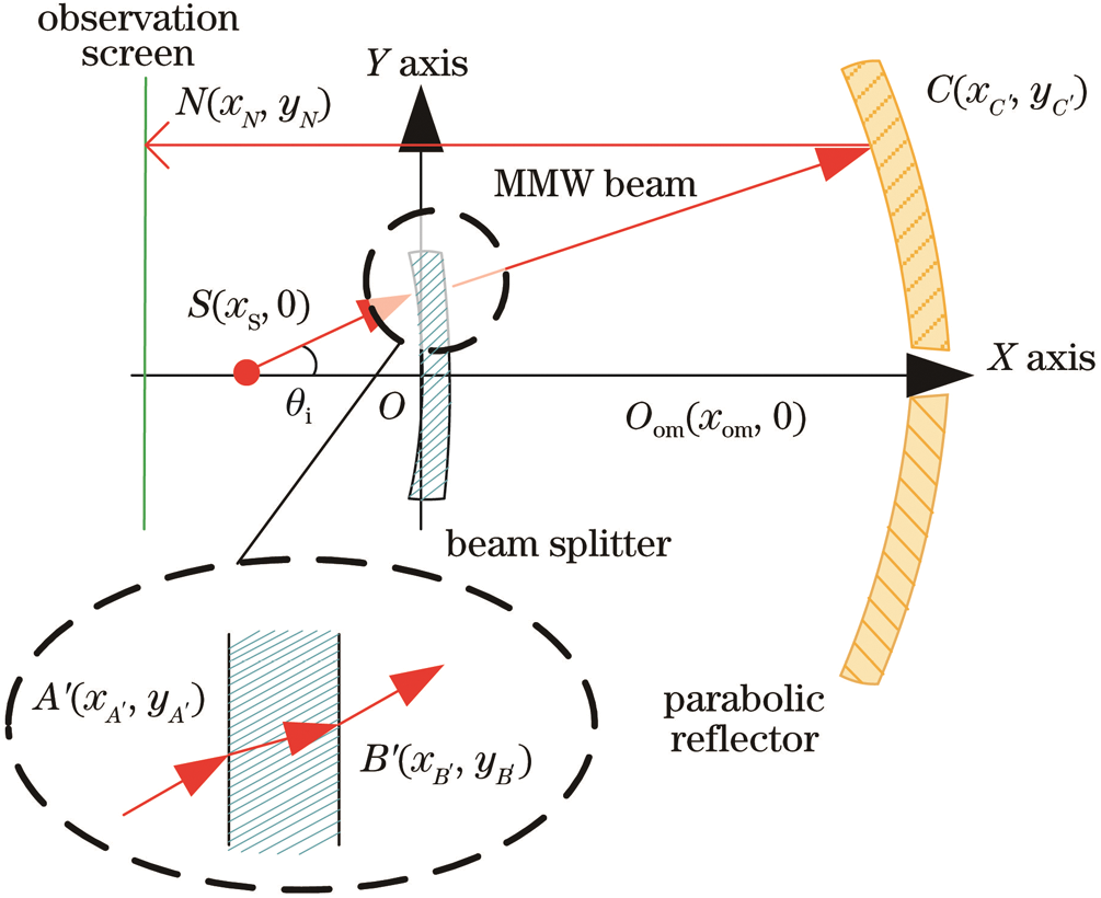
Figure 2: Proposed model for hybrid transmission line
The position of the millimeter-wave feed is denoted as  , and the subscript
  represents the feed; the center of the front surface of the dielectric dichroic mirror is at
  , and the vertex of the parabolic mirror is at
  . The subscript om indicates the vertex of the parabolic mirror. Among them, the dielectric thickness of the dielectric dichroic mirror is d, the relative permittivity of the dielectric is
  , and the loss tangent is
  . The radius of curvature of the back surface of the dielectric dichroic mirror is
  , and the subscript
  represents the back surface of the dichroic mirror. The curvature radius of the front surface is
  , and the subscript
  represents the front surface of the dichroic mirror. The radius of curvature of the parabolic mirror is
  , and the subscript
  represents a parabolic mirror. The direction function of the electric field intensity of the feed is denoted as
  , and
, and  is the spatial direction angle.
The front surface of the dielectric dichroic mirror can be expressed as

Tracing the ray  in the
  direction, the ray slope
  , the position of the point
  can be expressed as

The interface normal slope k1 at point  can be expressed as

Therefore, the incident angle  at the interface of the front surface of the dichroic mirror can be expressed as

According to the law of refraction, the refraction angle  at point
  is
is

From the refraction angle  , the slope of the ray
  is
is

Furthermore,  can be expressed as
  and the rear surface equation of the dichroic mirror is combined to solve the
  point position, namely

After the ray is refracted by the dichroic mirror, it exits from point  , reflects at point
  on the parabolic mirror, and reaches point N on the observation surface after reflection. Among them, the slope of the ray
  can be expressed as

where  is the refraction angle at the interface of point
  on the back surface of the dichroic mirror, similar to the method of finding the refraction angle
  at point
  on the front surface of the dichroic mirror,
  can be obtained by the law of refraction; k2 is the point-slope of the normal line at the interface of point
  on the back surface of the color mirror,
  . Therefore,
  can be expressed as
  , and the parabolic reflection mirror surface can be expressed as
  , and the two equations can be obtained simultaneously at
  point position.
The slope of the interface normal at the point  is
is  , the incident angle
  at point
  at the reflecting surface can be expressed as

For a parabolic mirror, the incident angle is equal to the reflection angle, so the slope  of the ray
  can be expressed as

The expression of  is
is  , from which the position coordinates of the millimeter-wave ray in the
  direction emitted by the feed and finally landed on the observation surface at point N can be obtained.
Only tracing the light will ignore the loss of the lossy dielectric dichroic mirror to the millimeter-wave, so it is necessary to analyze the attenuation of the millimeter-wave signal by the dichroic mirror from the trace to the dichroic mirror. Since the radius of curvature and size of the dielectric dichroic mirror is relatively large relative to the working wavelength of the antenna, the dielectric dichroic mirror can be locally approximated as a flat plate structure [19], and the microwave passing through the different positions of the lens is regarded as a local plane wave passing through the flat medium. According to the transmission line theory, for the uniform transmission line circuit shown in Fig. 3, the transmission line expression is

where U0 and I0 are the voltage and current of the input port of the transmission line respectively; U2, I2 are respectively the voltage and current of the output port of the transmission line; Zc is the characteristic impedance of the transmission line.  is the propagation constant, where
  and
and  are the attenuation and phase constants. l is the length of the uniform transmission line.
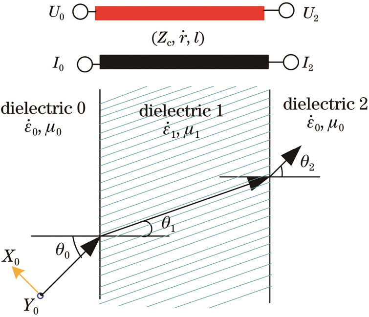
Figure 3: Uniform transmission line circuit equivalent and dielectric representation
In Fig. 3, the incident angle of the microwave from medium 0 to medium 1 is  , the refraction angle is
  , and the refraction angle
  of microwave exiting from 1 to medium 2. Since it is a single-layer board, medium 0 and medium 2 are the same media. Assuming that the permeability of medium 0 (medium 2) is
  , the complex permittivity is
  , the permeability of medium 1 is
  , and the complex permittivity is
  . According to the boundary conditions, the uniformity is shown in Fig. 3 horizontal polarization transfer matrix equation and the vertical polarization transfer matrix equation of anisotropic dielectric plate can be unified as

where Zcn is the equivalent characteristic impedance of the medium n(n = 0, 1, 2), the subscript c indicates that the impedance is the equivalent impedance, and the subscript n indicates the order relationship of the medium along the microwave propagation direction; d is the thickness of the medium plate;  is the equivalent propagation constant, where k1 is the propagation constant in medium 1, and
  is the angular frequency. For horizontal (vertical) polarized waves, Y0 is the tangential electric field (magnetic field) component of the boundary between medium 0 and medium 1, and X0 is the tangential magnetic field (electric field) component of the boundary between medium 0 and medium 1. For horizontal (vertical) Polarized wave, Y2 is the tangential electric field (magnetic field) component of the boundary between medium 1 and medium 2; X2 is the tangential magnetic field (electric field) component of the boundary between medium 1 and medium 2.
Comparing Eqs. (11) and (12), it can be seen that the transfer matrix equation is in the same form as the transmission line equation, and  is corresponding to
  . Therefore, the dielectric dichroic mirror can be partially regarded as a transmission line [20,21].
The equivalent characteristic impedance of vertically polarized and horizontally polarized waves is different, which can be expressed as

where  is the equivalent impedance of horizontally polarized waves;
  is vertically polarized waves equivalent impedance; Zn is the characteristic impedance;
  is the permeability;
  is the complex permittivity;
  is the incident angle.
Solving the transmission line matrix equation, the transmission coefficient of the single-layer flat plate can be obtained as

From Eq. (14), the transmittance of the millimeter-wave ray signal of the feed in the  direction after passing through the dichroic mirror of the lossy medium can be obtained.
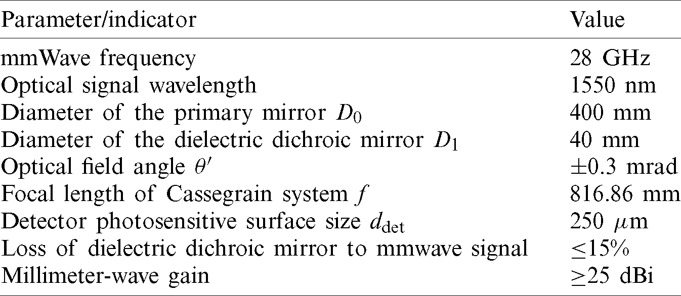
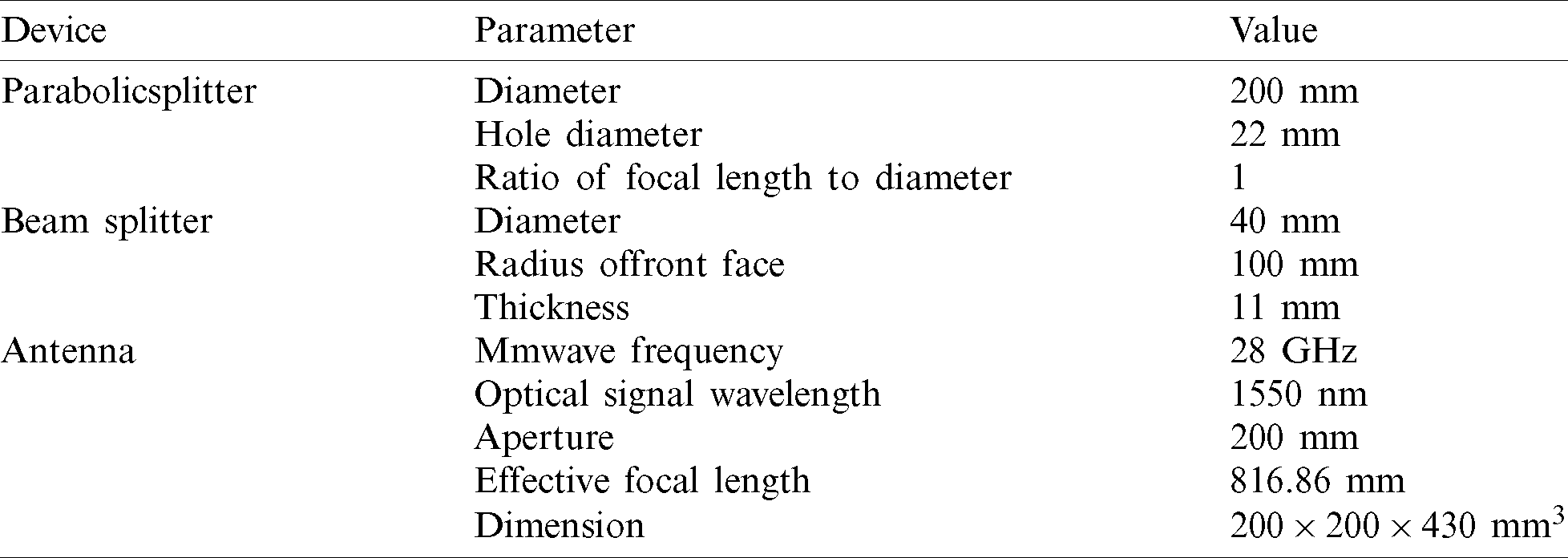
The technical indicators of the composite antenna are shown in Tab. 1.
Table 1: Design specification of the proposed hybrid antenna structure
3.1 Composite Antenna Optical Structure Design
It can be seen from Fig. 1 that when the composite antenna is used as the transmitting end, it can be regarded as the light source passing through the optical antenna and imaging at infinity. In the design process, if light tracing is carried out from the object to the image, it is inconvenient to evaluate the performance of the optical system. According to the principle of reversibility of the optical path, light can be traced backward. To facilitate the design and evaluation of the optical antenna, the design can be carried out from the receiving end of the optical antenna.
The design is performed using the reverse design method, calculate the structural parameters of the parabolic mirror and the dielectric dichroic mirror from the optical relationship, add an aspheric correction lens on this basis, and use the global optimization function in ZEMAX to design and optimize the optical system structure (Fig. 4), the structural parameters are shown in Tab. 2.
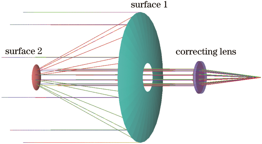
Figure 4: Proposed optical antenna structure
Table 2: Design parameters of the optical antenna
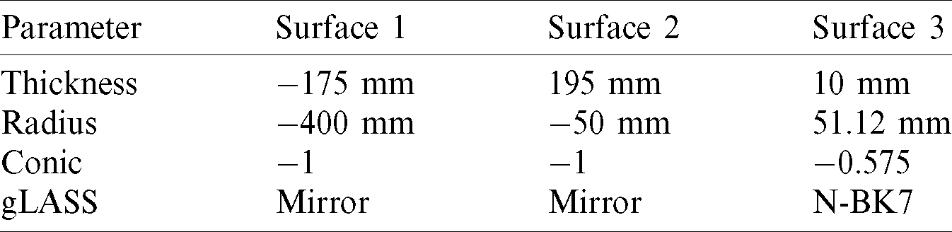
According to the output parameters of ZEMAX, the diameter of the primary mirror of this structure is D0 = 400 mm, the diameter of the dielectric dichroic mirror is D1 = 40 mm, and the focal length of the system f = 816.86 mm, which meets the design requirements.
3.2 Optimal Design of Mmwave Antenna
The optimized design of the antenna millimeter-wave structure uses the sinc function to simulate the millimeter-wave feed pattern of a certain beam width 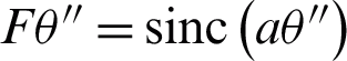 , where a is the coefficient, and when
  is the half-power width W,
  .
.
The dielectric dichroic mirror needs to be coated with a film system that highly reflects the optical signal. Quartz is selected as the dielectric dichroic mirror material, its relative permittivity  , and the loss tangent value
  . The dielectric lens separately with center thickness d, the front surface curvature radius is
  and the position of the millimeter-wave feed from the dielectric dichroic mirror and the feed direction. We use the TLTG-RTM hybrid algorithm to find the relative electric field distribution on the observation surface. The results are shown in Fig. 5.
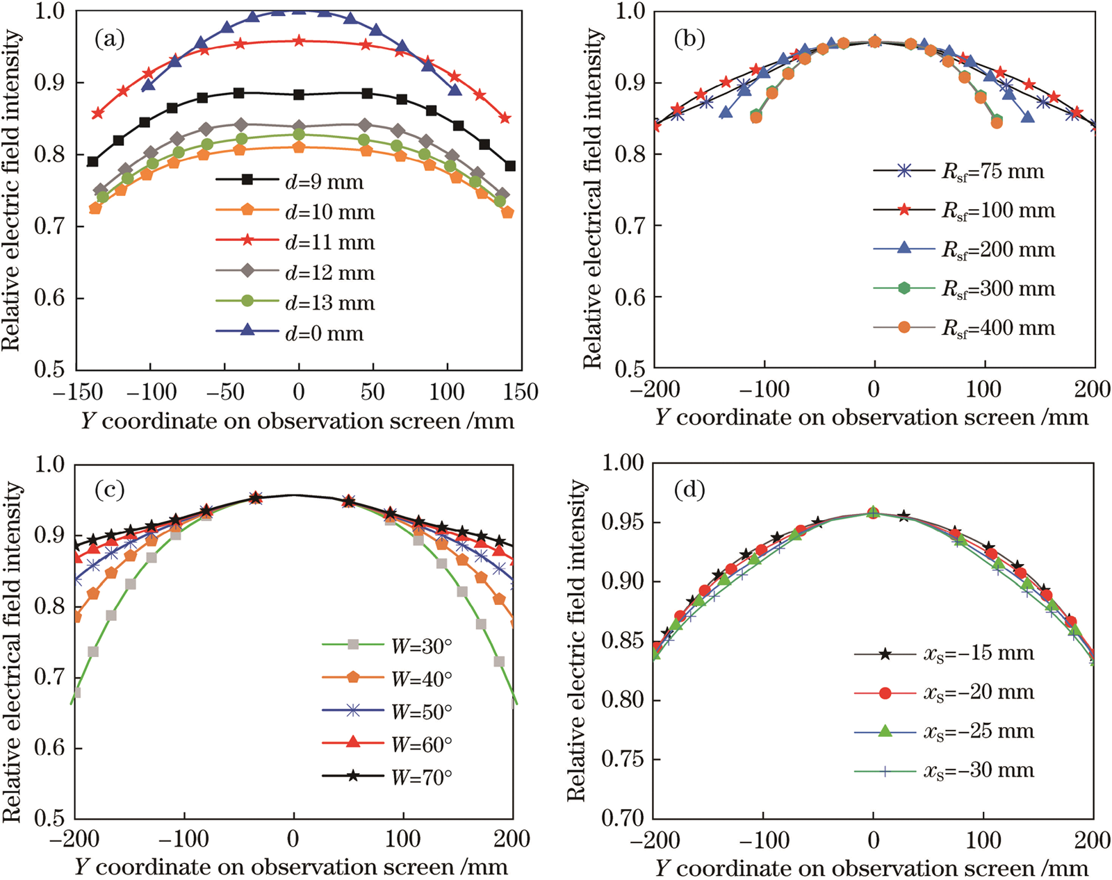
Figure 5: Impact of design parameters on relative electric field distribution. (a) Center thickness d of beam splitter; (b) curvature beam splitter front surface  ; (c) half-power bandwidth of feed W; (d) feed location
It can be seen from Fig. 5a that changing the center thickness d of the dielectric dichroic mirror will change the relative electric field intensity distribution. When d = 11 mm, the loss of millimeter waves passing through the dielectric dichroic mirror is a minimum. Therefore, the center thickness of the dielectric dichroic mirror is 11 mm. It can be seen from Fig. 5b that when the radius of curvature of the front surface is  mm, the millimeter-wave loss is a minimum and the divergence angle is small. Fig. 5c shows the distribution curve of the relative electric field on the observation surface when the half-power width (W) of the transmitting feed is changed. The larger the half-power width, the better the collimation performance of the composite antenna for millimeter waves, and the smaller the total loss, but the beam width cannot be too large, otherwise it will make the antenna emission efficiency is reduced because the beam width is much larger than the size of the parabolic mirror. Fig. 5d reflects the influence of the feed position
  on the loss. It can be seen that the feed position has little effect on the loss of millimeter waves passing through the dichroic mirror within a certain range; therefore, the center of the feed is placed on the parabolic reflector at the focal point of the mirror. Based on the above analysis, the structural parameters of the composite antenna are determined as shown in Tab. 3.
Table 3: Design parameters of the proposed antenna
According to the structure of the above hybrid antenna, two-dimensional space tracking is performed in the Matlab simulator based on TLTG-RTM, and the power transmittance of the dielectric dichroic mirror in the  tracking direction is calculated. Since the radius of the curvature of the dichroic mirror is relatively large relative to the working wavelength of the antenna, it can be locally approximated as a dielectric plate. Therefore, a millimeter-wave transmission medium plate model is established in FEKO to obtain the power transmission of the dielectric dichroic mirror in the same tracking direction. Comparing the calculation results of the two, it is found that the two are the same. The power transmittance in different tracking directions calculated by the TLTG-RTM hybrid algorithm is shown in Fig. 6, and the average transmittance is 90.09%, so the loss of the dielectric dichroic mirror is
  = 1-90.09% = 9.91%, which meets the design requirements.
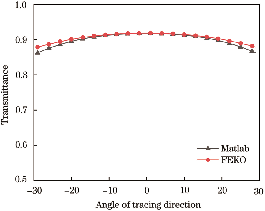
Figure 6: Comparison of transmittance vs. direction of angle tracing
According to the composite antenna structure in Tab. 3, a 28 GHz circular mouth horn is used as the millimeter-wave feed. The model is shown in Fig. 7 is established in FEKO. The center of the feed is at the focal point of the parabolic mirror, and the distance is r. In a spherical coordinate system 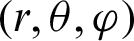 with an elevation angle of
  and an azimuth angle of
  , the MLFMM algorithm is used to calculate the electric field distribution
  on a spherical surface surrounding the composite antenna, and the spherical radius is r0. Keep other conditions unchanged, remove the dielectric dichroic mirror, and calculate the electric field distribution
  of the structure on the spherical surface of the same radius. The radiation power P [18–21] can be expressed as

where r is the radius of the sphere.
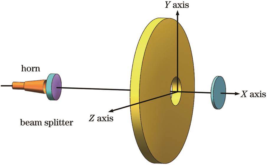
Figure 7: Design illustration of the hybrid antenna
According to Eq. (15), the electric field distributions  ,
,  are substituted into the electric field E respectively, and the two structures with and without the dichroic mirror are obtained the radiation powers P0 and P1. The loss of the dielectric dichroic mirror is obtained as
  1-90.38% = 9.62%, which meets the design requirements and is similar to the loss
  calculated based on TLTG-RTM consistent.
4.1 Optical Performance Analysis
The point spread function of the composite antenna is shown in Fig. 8. It can be seen that the point spread function of the optical antenna has high energy contrast on the image surface, the energy is concentrated, and there is no side lobe, and the imaging effect is very good. The optical transfer function of the composite antenna is shown in Fig. 9. When the optical system modulation transfer function curve drops to 0.7, the corresponding spatial frequency is 30 lp/mm, and the imaging quality is excellent. The transfer function of each field of view is close to the diffraction limit of the system. The actual imaging result is close to the ideal imaging result.
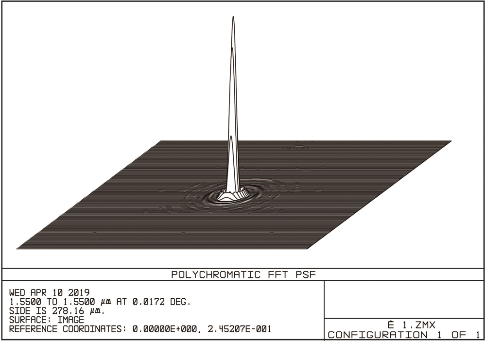
Figure 8: Analysis of point spread function
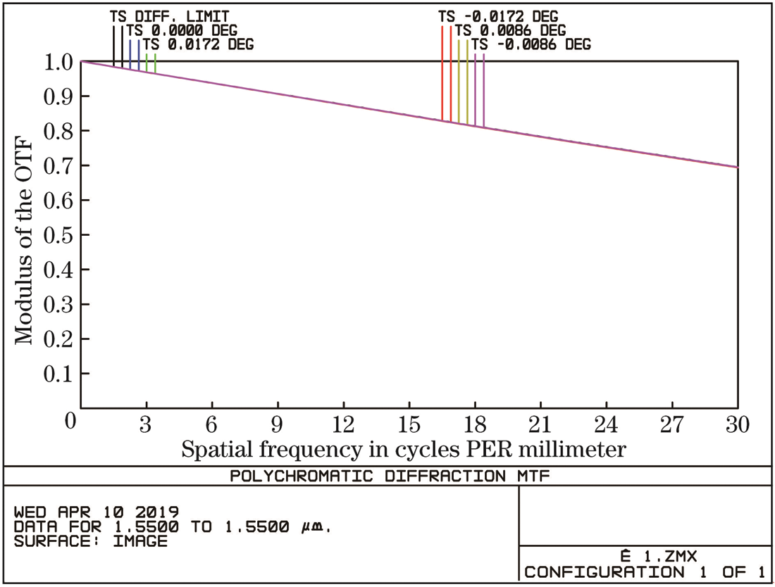
Figure 9: Analysis of modulation of the antenna
The intersection of the light and the image plane is used to calculate the enclosing energy circle of the optical system, and a circle is drawn from the center point with a certain radius, and the system is evaluated according to the ratio of the energy in the circle to the total energy. It can be seen from Fig. 10 that in the case of the diffraction limit, the detection A circle with a radius of 100  m on the surface contains 99.87% of the total energy, a circle with a radius of 100
  m on the detection surface under a
  field of view contains 99.87% of the total energy, and a field of view of
  corresponds to 99.86% of the total energy is close to the diffraction limit. The size of the photosensitive surface of the detector is 250
  m, which can receive more than 99% of the energy, and the receiving efficiency is high.
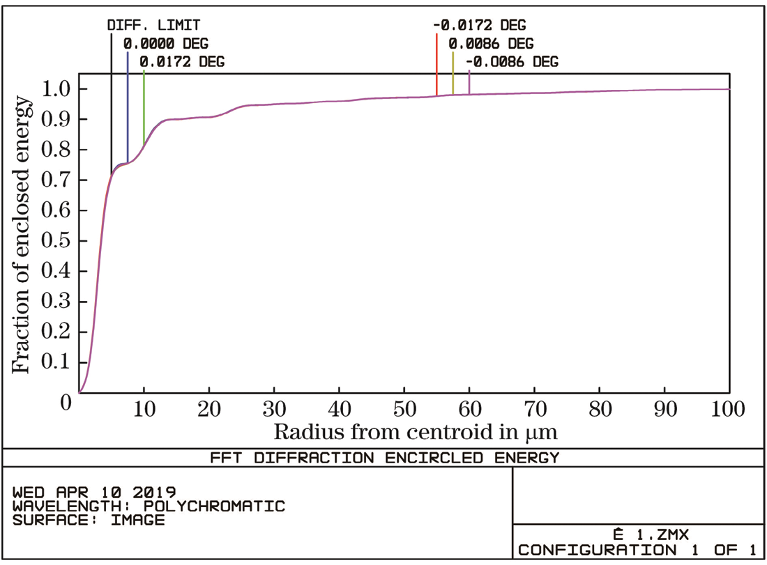
Figure 10: Fraction of energy distribution
4.2 Mmwave Performance Analysis
Using the commercial software FEKO, the MLFMM algorithm is used to calculate the millimeter-wave far-field pattern of the composite antenna as shown in Fig. 11. It can be seen from Fig. 11 that the far-field pattern of the antenna is a typical pen-shaped antenna pattern, with good directivity, the main lobe gain is 32.97 dBi, the half-power width is  , and the null beam width is
  , so the mmwave gain meets the design requirements. The composite antenna has rotational symmetry. As shown in Fig. 11a, since the far-field pattern of the E plane and the H plane are the same, only the far-field pattern of the H plane is shown in Fig. 11b. The feed also has Rotational symmetry, the far-field pattern of the H-plane is shown in Fig. 11b, the main lobe gain of the feed is 14.56 dBi, and the half-power width is
  . It can be seen that the composite antenna can better collimate and focus millimeter-wave signals.
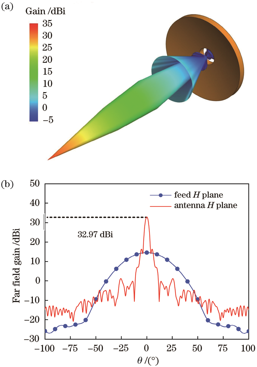
Figure 11: Proposed antenna analysis in far-field. (a) 3D direction (b) gain
Since the dichroic mirror is a lossy medium, the millimeter-wave transmission dichroic mirror will cause energy loss. Also, energy will leak from the middle hole of the parabolic mirror and diffract from the edge of the parabolic mirror. Let  denote the energy loss of the composite antenna which is expressed as

where  is the main beam radiation power of the composite antenna millimeter-wave and P0 is the input power. In the spherical coordinate system
  ,
,  can be expressed as

where  is the power density. Since the gain
  , where SM is the antenna power density, SAV is the non-directional antenna power density of the same input power, so according to the composite antenna far-field pattern, from Eqs. (16) and (17), the energy loss
  can be obtained.
This paper proposed a novel broadband hybrid antenna for 5G networks. The designed structure is aimed to work in both optical and mm-wave bands. Also, we proposed a hybrid transmission and ray-tracing technique for evaluation and analysis of the proposed antenna which not only has the advantages of high geometrical optics calculation efficiency but also can obtain more accurate calculation results. It is suitable for the fast and efficient optimization design of electrically large composite antennas containing lossy dielectrics. The composite antenna optimized and designed using this hybrid algorithm can realize the common-aperture composite of a free-space optical signal with a wavelength of 1500 nm and a millimeter-wave signal with a frequency of 28 GHz. The effective aperture of the composite antenna is 200 mm, the field of view angle is 0.3 mrad, and the modulation transfer function in each field of view is close to the diffraction limit. The loss of the dielectric dichroic mirror to the millimeter-wave is about 9%, the millimeter-wave gain can reach 32.97 dBi, and the half-power width is only  , which is a typical pen antenna pattern type has good directivity and can be used for composite transmission of optical signals and millimeter-wave signals of point-to-point ground links in 5G communications. However, the loss caused by hole overflow and leakage is as high as 49.28%, so reducing the loss of the composite antenna is the research direction of the next design.
Acknowledgement: The author would like to thank the editor and reviewers for their timely review and recommendations.
Funding Statement: The author received no specific funding for this study.
Conflicts of Interest: The author declare that they have no conflicts of interest to report regarding the present study.
References
1. O. A. Saraereh, I. Khan, B. M. Lee and A. K. S. Al-Bayati. (2018). “Modeling and analysis of wearable antennas,” Electronics, vol. 8, no. 1, pp. 1–12.
2. A. Iqbal, A. Smida, L. F. Abdulrazak, O. A. Saraereh, N. K. Mallat et al. (2019). , “Low-profile frequency reconfigurable antenna for heterogeneous wireless systems,” Electronics, vol. 8, no. 9, pp. 1–11.
3. A. Iqbal, A. Smida, O. A. Saraereh, Q. H. Alsafasfeh, N. K. Malla et al. (2019). , “Cylindrical dielectric resonator antenna-based sensors for liquid chemical detection,” Sensors, vol. 19, no. 5, pp. 1–9.
4. M. Miao and X. Li. (2020). “Gallager exponent analysis of coherent MIMO FSO systems over gamma–gamma turbulence channels,” Entropy, vol. 22, no. 11, pp. 1–20.
5. M. Z. Chowdhury, M. Shahjalal, M. K. Hasan and Y. M. Jang. (2019). “The role of optical wireless communication technologies in 5G/6G and IoT solutions: Prospects, directions, and challenges,” Applied Sciences, vol. 9, no. 20, pp. 4367.
6. S. Althunibat, R. Massieh and K. Qaraqe. (2020). “Secure index-modulation-based hybrid free-space optical and millimeter-wave links,” IEEE Transactions on Vehicular Technology, vol. 69, no. 6, pp. 6325– 6332.
7. Z. Ghassemlooy, H. Le Minh, S. Rajbhandari, J. Perez and M. Ijaz. (2012). “Performance analysis of ethernet/fast-ethernet free-space optical communications in a controlled weak turbulence condition,” Journal of Lightwave Technology, vol. 30, no. 13, pp. 2188–2194.
8. A. Vavoulas, H. G. Sandalidis and D. Varoutas. (2012). “Weather effects on FSO network connectivity,” Journal of Optics Communications and Networking, vol. 4, no. 10, pp. 734–740.
9. F. Demers, H. Yanikomeroglu and M. S. Hilaire. (2011). “A survey of opportunities for free-space optics in next-generation cellular networks,” in IEEE 9th Annual Communication Networks and Services Research Conf., Ottawa, Canada, pp. 210–216.
10. N. Tien, J. Rhee and S. Park. (2018). “A novel effective multipath routing technique providing high availability in wireless networks,” Electronics, vol. 7, no. 4, pp. 1–19. [Google Scholar]
11. M. M. Abadi, Z. Ghassemlooy, M. R. Bhatnagar, S. Zvanovec, M. A. Khalighi et al. (2018). , “Differential signaling in free-space optical communication systems,” Applied Sciences, vol. 8, no. 6, pp. 1–20. [Google Scholar]
12. R. Haluska, P. Sulaj, L. Ovsenik, S. Marchevsky, J. Papaj et al. (2020). , “Prediction of received optical power for switching hybrid FSO/RF system,” Electronics, vol. 9, no. 8, pp. 1261. [Google Scholar]
13. D. Feng, W. Q. Sun and W. S. Hu. (2017). “Hybrid radio frequency and free space optical communication for 5G backhaul,” in IFIP/IEEE Symp. on Integrated Network and Service Management, Portugal, pp. 616–619. [Google Scholar]
14. T. Jiang, L. Zhao, H. Liu, D. Deng, A. Luo et al. (2019). , “Performance improvement for mixed RF-FSO communication system by adopting hybrid subcarrier intensity modulation,” Applied Sciences, vol. 9, no. 18, pp. 1–13. [Google Scholar]
15. M. M. Abadi, Z. Ghassemlooy, D. Smith and P. W. Ng. (2013). “A report on H-FSO/RF antenna measurement for outdoor applications,” in IEEE 2nd Int. Workshop on Optical Wireless Communications, pp. 118–122. [Google Scholar]
16. M. M. Abadi, Z. Ghassemlooy, S. Zvanovec, D. Smith, M. R. Bhatnagar et al. (2016). , “Dual purpose antenna for hybrid free space optics/RF communication systems,” Journal of Lightwave Technology, vol. 34, no. 14, pp. 3432–3439. [Google Scholar]
17. H. Yang, P. Jiang, W. He and S. Ke. (2014). “Optimum design of aspheric collimation lenses for optical antenna system,” Journal of Optik, vol. 125, no. 14, pp. 3469–3472. [Google Scholar]
18. F. A. R. Corbo, L. Azpilicueta, M. C. Echarri, P. L. Iturri and I. Picallo. (2020). “Deterministic 3D ray-launching millimeter wave channel characterization for vehicular communications in urban environments,” Sensors, vol. 20, no. 18, pp. 1–25. [Google Scholar]
19. Z. Duan, G. Abomakhleb and G. Lu. (2019). “Perforated medium applied in frequency selective surfaces and curved antenna radome,” Applied Sciences, vol. 9, no. 6, pp. 1–12. [Google Scholar]
20. P. K. Velpula, D. Kramer and B. Rus. (2020). “Femtosecond laser-induced damage characterization of multilayer dielectric coatings,” Coatings, vol. 10, no. 6, pp. 603. [Google Scholar]
21. C. A. Balanis. (1992). “Antenna theory: A review,” Proceedings of the IEEE, vol. 80, no. 1, pp. 7–23. [Google Scholar]
 | This work is licensed under a Creative Commons Attribution 4.0 International License, which permits unrestricted use, distribution, and reproduction in any medium, provided the original work is properly cited. |