DOI:10.32604/cmc.2021.014786
| Computers, Materials & Continua DOI:10.32604/cmc.2021.014786 | |
| Article |
An Efficient Fuzzy Logic Fault Detection and Identification Method of Photovoltaic Inverters
1Department of Electrical Engineering, Aswan University, Aswan, 81542, Egypt
2Electronics Engineering Department, Universidad Tecnica Federico Santa Maria, Valparaiso, 2390123, Chile
3College of Engineering at Wadi Addawaser, Prince Sattam Bin Abdulaziz University, Wadi Addawaser, 11991, Saudi Arabia
4Electrical Engineering Department, Faculty of Engineering, Minia University, Minia, 61111, Egypt
*Corresponding Author: Hegazy Rezk. Email: hr.hussien@psau.edu.sa
Received: 16 October 2020; Accepted: 17 November 2020
Abstract: Fuzzy logic control (FLC) systems have found wide utilization in several industrial applications. This paper proposes a fuzzy logic-based fault detection and identification method for open-circuit switch fault in grid-tied photovoltaic (PV) inverters. Large installations and ambitious plans have been recently achieved for PV systems as clean and renewable power generation sources due to their improved environmental impacts and availability everywhere. Power converters represent the main parts for the grid integration of PV systems. However, PV power converters contain several power switches that construct their circuits. The power switches in PV systems are highly subjected to high stresses due to the continuously varying operating conditions. Moreover, the grid-tied systems represent nonlinear systems and the system model parameters are changing continuously. Consequently, the grid-tied PV systems have a nonlinear factor and the fault detection and identification (FDI) methods based on using mathematical models become more complex. The proposed fuzzy logic-based FDI (FL-FDI) method is based on employing the fuzzy logic concept for detecting and identifying the location of various switch faults. The proposed FL-FDI method is designed and extracted from the analysis and comparison of the various measured voltage/current components for the control purposes. Therefore, the proposed FL-FDI method does not require additional components or measurement circuits. Additionally, the proposed method can detect the faulty condition and also identify the location of the faulty switch for replacement and maintenance purposes. The proposed method can detect the faulty condition within only a single fundamental line period without the need for additional sensors and/or performing complex calculations or precise models. The proposed FL-FDI method is tested on the widely used T-type PV inverter system, wherein there are twelve different switches and the FDI process represents a challenging task. The results shows the superior and accurate performance of the proposed FL-FDI method.
Keywords: Fault detection and identification; fuzzy logic; T-type inverter; photovoltaic (PV)
Recently, photovoltaic (PV) generation systems have found wide concerns in electricity generation due to the reductions in the reserves of fossil fuel sources [1]. Additionally, the negative impacts on environment and the global warming concerns represent the main issues of the conventional fossil fuel generations. This in turn has resulted in increasing the installed PV systems in the utility grids in addition to the ambitious future installation plans. The recent energy reports show that the electricity generation by PV systems is increasing exponentially [2].
The increased installations and the dependency of future grids on the PV generation system have increased potential for the reliability, energy efficiency, and cost reduction as major concerns for industry and research [3,4]. The field based statistics have showed that the power converters of PV systems are the most vulnerable part amongst the other parts. Power converters are mainly constructed of electrolytic capacitors, power switches, and passive elements. The power switches related failures are the most common types of shutdown of PV systems [5–7]. Therefore, detection of the power switches faults and identify their locations are very important for reliable operation of PV generation systems.
From another side, multilevel inverters have proven superior performance over the traditional two-level topologies for wide output power ranges [8]. The main playing factors behind these advantages are the low  values, reduced harmonics, and low voltage ratings of components. Moreover, the output grid filter components are reduced by using multilevel inverter topologies. This in turn results in reducing volume, weight, and cost of PV systems. There are several multilevel inverter topologies in the literature for the grid-tied PV installations. Among the various existing topologies, the T-type three-level inverter topology has been widely presented from research and industry [9,10]. The main advantages of T-type topology are the elimination of clamping diodes and flying capacitors, using lower rating switches, and reducing the conduction losses in the power switches.
The continuous power supply of PV systems requires the fast detection of abnormal conditions due to faults and transients. The accurate and fast detection of faults would reduce the number and time of maintenance and repair of faulty parts [11]. Mainly, there are two different types of faults in power switches, including the open circuit fault, and short circuit fault. In the short circuit faults, the system is required to shutdown to prevent accumulated damage of the other parts due to the high abnormal generated fault overcurrent [4]. Normally, fuses are utilized to open the circuit of the power switch at short circuit faulty condition. Whereas, the open circuit faults introduce distortions in the output of the inverter and proper detection is highly needed. The open circuit faults in T-type inverters lead to imbalance among the dc-link capacitors, which accumulates with time and hence higher voltage stresses on the capacitors and switches are produced [12,13]. Thence, accurate fault detection and identification of faulty switch location is highly important in order to increase the reliability, and stability of PV generation system supply.
Several methods have been presented in the literature for detecting the open circuit faults of both the two-level and three-level inverters [14–16]. General review of the existing detection and identification methods for faults in the cascaded H-bridge (CHB) inverters has been presented in [17]. In [18], fast open circuited switch fault has been proposed for fault tolerant two-level inverters in active power filter applications. The detection of the fault is achieved through comparing the voltage difference in magnitude and time between the measured and calculated output voltages. However, additional sensors and accurate model of the system are required in this type of fault detection. Another similar fault detection method for two-level and three-level NPC topology has been proposed in [18,19], however it fails at identifying the location of faults switch. Concordia transform based fault detection method has been presented in [20] using the measured output current of the inverter within the line period. Unfortunately, it require an additional fundamental period for inductive current injection to identify the place of the faulty switch. Additional methods based on ac-current slope and the zero voltage switching state have been presented in [21]. Although, this method represents a slow fault detection solution due to requiring three fundamental line periods to detect and identify the faulty switch.
In [22], historical average voltage values based fault detection method has been presented for the CHB topology. The method is capable of locating the faulty switch pair without determining the faulty one. A modified method has been presented in [23] with adding another voltage sensors to locate exactly the faulty switch. A method based on the state estimators and the current residual has been proposed in [24]. Although, this method neglects the dynamic behavior of multilevel inverters. From another side, the neural network has been proposed for fault detection in CHB multilevel inverter topology [25]. A Real-time switch fault detection method based on 1-D convolutional neural networks (CNN) has been presented in [26]. These methods can properly detect the faulty switch and its location, however, complex computation and learning data are needed in this type. Additional methods have been introduced using the simplified Fourier transform [27], observer based [28], CNN [29], and deep CNN [30],
Principal component analysis (PCA) based fault detection method has been proposed in [31]. However, this method requires additional measurements, which increase the cost of the system. Application of artificial neural network and fuzzy logic methods for detection of faulty switches have been proposed in the literature [32–34]. However, the existing methods fail at exactly localizing the faulty switch. Additionally, the model predictive control (MPC) methods have been employed for detecting faults in power converters [35,36]. These methods employ the already estimated states against the actual measured ones to detect the faulty condition. Fuzzy logic based method for detecting the faults in two-level based motor drive applications using the measured currents has been proposed in [34].
It can be seen that the existing fault detection methods focus on the two-level inverters and motor drive applications. Whereas, the grid-tied applications are subjected to continuously varying operating conditions and parameters variations. Thence, the behavior of the grid-tied PV systems is difficult to be predicted by mathematical modelling in addition to continuous variations in the grid side impedance. Thence, nonlinearity would appear in case of open circuit faults occurrence. Therefore, this paper proposes an efficient fault detection and identification method for open circuit faults for grid-tied T-type PV inverter applications. The proposed method is based on employing the fuzzy logic for detecting and relocating the various faults. The proposed method represents a simple method with considering nonlinearities and parameter variations of grid-tied PV systems. Moreover, the proposed method eliminates the need for the additional measurement circuits and/or complex mathematical modelling.
The remaining of the paper is organized as following: the operating principle and power circuit of grid-tied T-type PV inverter is presented in Section 2. The post-fault analysis of the PV inverter is explored in Section 3. The proposed fault detection method is detailed in Section 4 with the design considerations of the proposed algorithm. The results of the selected case study and performance criteria of the proposed method are given in Section 5. Section 6 presents the conclusion of the paper.
2 Operation and Structure of Grid-Tied T-type PV Inverter
The power circuit of the three-phase grid-tied three-level T-type PV inverter topology is described in Fig. 1. The topology has twelve power switches with four switches in each phase. The input dc-link voltage is equally divided among the two dc-link capacitors at steady state (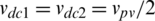 ). The dc-link capacitors are responsible for generating the different voltage levels in the inverter. The incorporation of different twelve power switches results in making the fault detection and identification process more complex for T-type inverters. The operation of the topology can be explained as follows: each phase leg in the topology can generate one of three states (P, O, or N) according to the applied gating pulses. The associated output voltages for the three states are
  , 0, and
  , respectively. The controller has to maintain balanced voltages over the dc-link capacitors in order to avoid the voltage overstresses on the different components in the inverter system. The switches pulses for each phase leg is shown in Tab. 1.
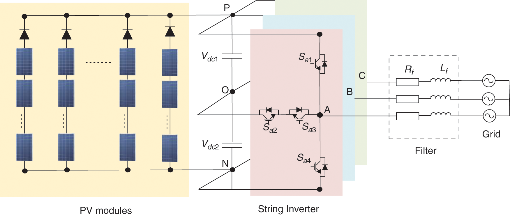
Figure 1: Grid-connected three-level T-type inverter
Table 1: The switching states and switch status of the T-type topology
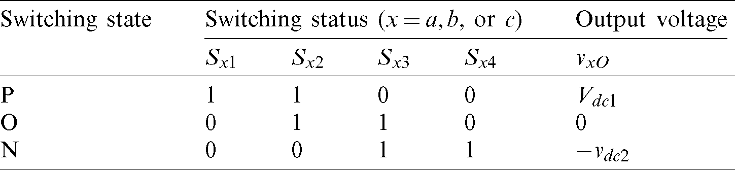
Fig. 2 shows the control system for the three-phase grid-tied T-type topology for the PV systems. The phase locked loop (PLL) is firstly employed to provide the grid synchronization function for the inverter. The maximum power point tracking (MPPT) block maximizes the extracted power from the PV systems at the various operating solar irradiance and ambient temperature. The MPPT controller generates the reference dc-link voltage for the inverter, which is responsible for generating the d-axis reference current. The d-q reference frame is utilized in this paper for performing the inverter control. The q-axis reference current is determined according to the required reactive power injection by the inverter. Two differ proportional-integral (PI) decoupled controllers are used for performing the d-q-axis current control.
Figure 2: The control structure of the grid-tied PV inverter
3 Post-Fault Analysis of T-Type Inverter
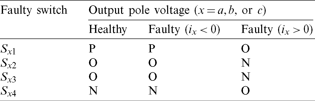
In case of open circuit fault condition, some switching states will be impossible and freewheeling diodes results in different states at the output depending on the current direction and the faulty switch location. Tab. 2 shows the healthy and faulty output states of the inverter at different fault locations. It can be seen that when Sx1 is open circuited, the output voltage state will remain the same at negative output grid current due to the freewheeling diode path. Whereas, at positive output current and faulty switch, the current direction will go through other freewheeling path in the neutral point switches. The same analysis can be made for the other faulty conditions. The change of the switching states at faulty condition results in the distortion of the output pole voltages, output grid currents, and dc-link capacitor voltages. The distortion is dependent on the state of the pole voltage and the direction of the grid current. In the following subsections, the analysis of the effects of different switches faults on the behavior of grid currents and the dc-link capacitor voltages are analyzed in more details for designing the proposed fault detection method.
Table 2: The effect of different faults and current direction on the states of output pole voltages
3.1 Analysis of the Output Grid Currents at Faulty Conditions
The inverter is controlled to generate a sinusoidal output currents in the normal case. At the faulty case, the path is determined by the location of faulty switch, the output current polarity, and the gating pulse. The inverter output states at faulty switch Sx1 is shown in Fig. 3a at positive polarity of output current, and in Fig. 3b for negative output current polarity. At negative output current, the path is determined by the freewheeling diode Dx1 of the switch at both the healthy and faulty cases and the output voltage will remain at P state without changes. Whereas, at positive current polarity, the output current will pass through the switch Sx2 and diode Dx3 and the pole voltage will change to state O. Similar analysis can be made for the other faulty switch cases. In case of switch Sx2 open circuit fault, the negative grid current will pass through diode Dx2. If the grid current is positive, the new path will be through diode Dx4 and the pole voltage will take the state N. In case of switch Sx3 open circuit fault, the negative grid current will pass through diode Dx3. If the grid current is positive, the new path will be through diode Dx1 and the pole voltage will take the state P. In case of switch Sx4 open circuit fault, the negative grid current will pass through diode Dx4. If the grid current is positive, the new path will be through switch Sx3 and diode Dx2 and the pole voltage will take the state O. The performance of the output current of the inverter at the various faulty switches is shown in Fig. 4. Tab. 2 summarizes the output state changes at different healthy and faulty conditions.
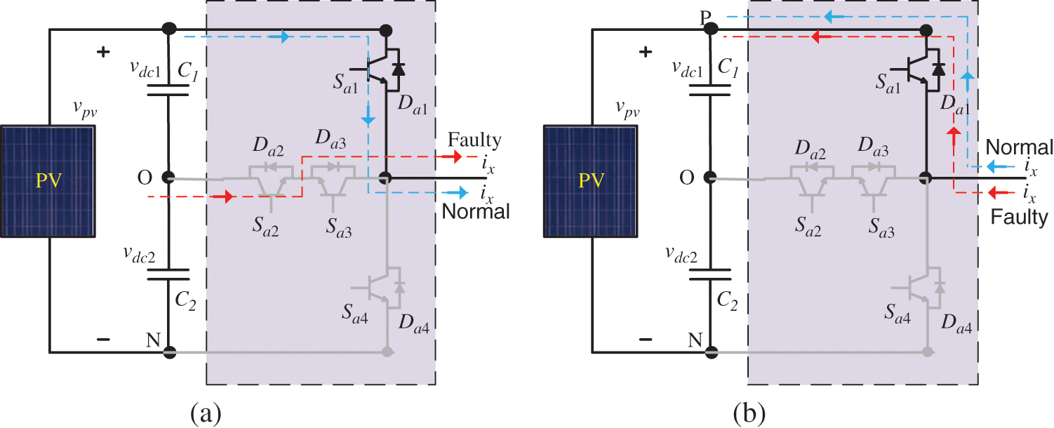
Figure 3: Current paths at normal and faulty conditions in the power switch Sa1. (a) Positive grid current (b) Negative grid current
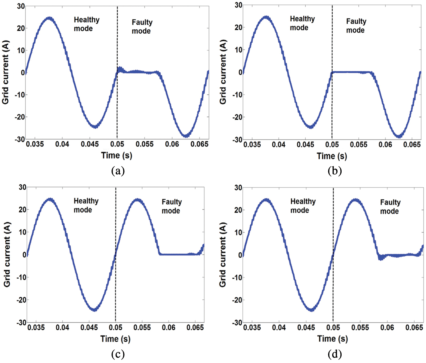
Figure 4: The behavior of grid current in different faulty modes. (a) Sa1 fault (b) Sa2 fault (c) Sa3 fault (d) Sa4 fault
3.2 Analysis of the dc-Link Capacitor Voltages at Faulty Conditions
The two capacitor voltages are highly influenced by the faulty switch and the applied switching states of phases a, b, and c. Fig. 5 shows the effect of different switching states on the dc-link capacitor voltages. The space vectors of the inverter output are categorized according to their magnitude into zero voltage, small voltage, medium voltage, and large voltage vectors. The neutral point (NP) is left unconnected in the large and zero voltage vectors, so they do not affect the NP voltage. On the other hand, medium-voltage vectors has a connection to NP, so they affect NP voltage. The NP voltage will increase or decrease depending on the current direction of its connected phase. In small voltage vectors, one or two of the three phases are connected to the NP, so they affect the NP voltage. The P-type small-voltage vectors helps to discharge the upper capacitor, and hence the NP voltage is increased. Conversely, the N-type small-voltage vectors discharges the lower capacitor that results in decreasing the NP voltage. More details about the NP voltage analysis with space vectors can be found in [15,37].
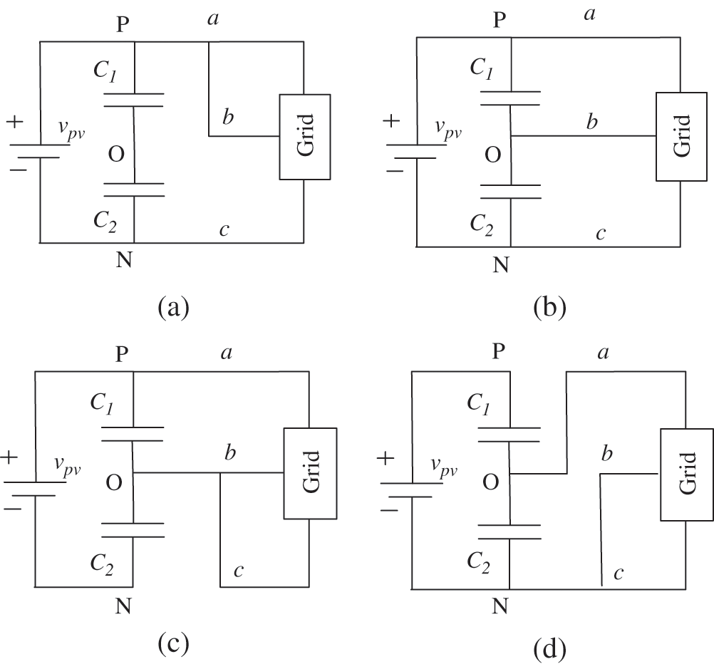
Figure 5: The effect of different switching space vectors on dc-link capacitors voltages. (a) PPN large voltage vector (b) PON medium voltage vector (c) POO P-type small voltage vector (d) ONN N-type small voltage vector
The two dc-link capacitors are expected to have equal voltages at healthy condition. When open circuit fault occurs, a change will occur in the output pole voltage state and hence the output space vectors, as described before in Tab. 3. In case switch Sx1 fault, the P state will be replaced with O. Consequently, some regions of the discharging of the upper capacitor will be replaced with lower capacitor discharging, and hence the upper capacitor will be higher than the lower capacitor voltage. A similar analysis can be made for other types of faults. Fig. 6 shows the two dc-link capacitor voltages at different types of faults.
Table 3: The rules of the fuzzy logic in the proposed method
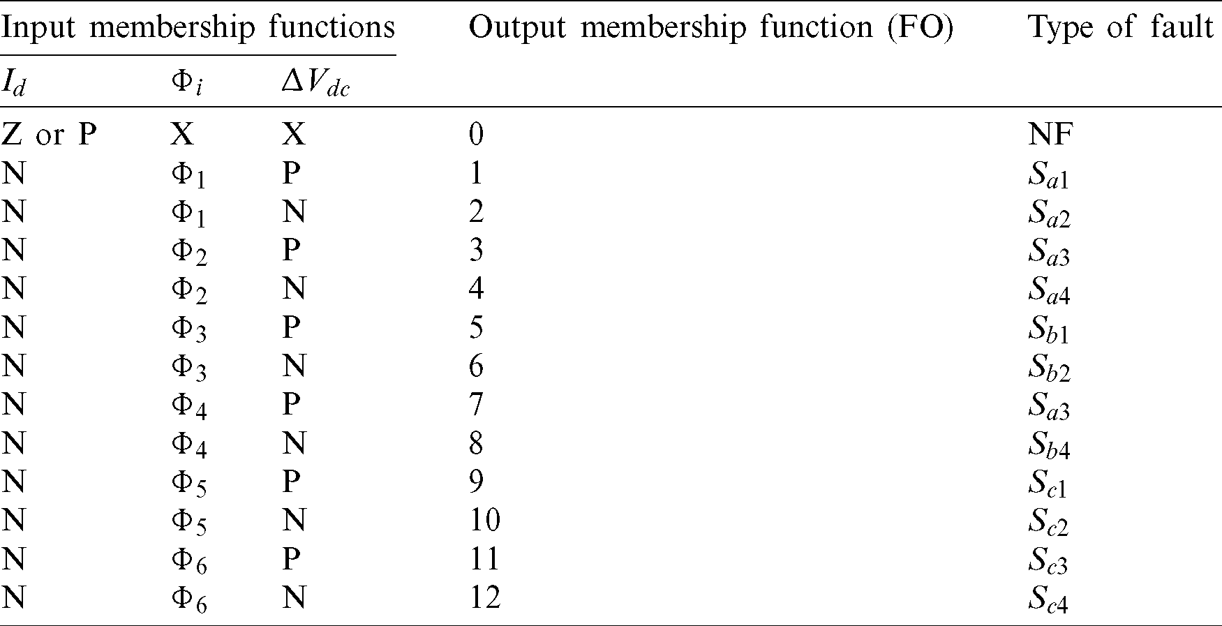
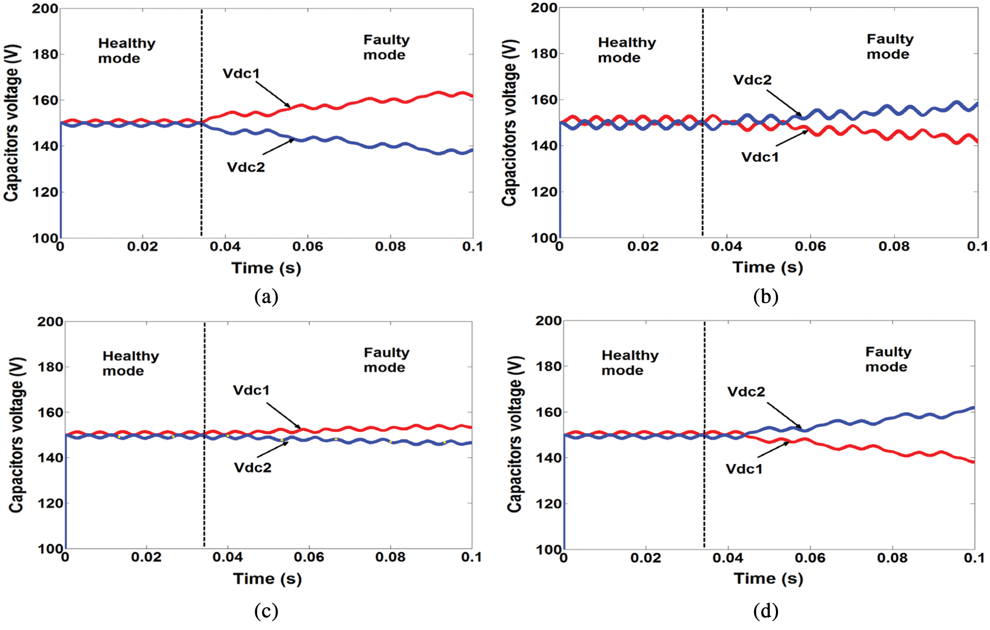
Figure 6: The behavior of dc-link capacitor voltages at different faults. (a) Sa1 fault (b) Sa2 fault (c) Sa3 fault (d) Sa4 fault
4 The Proposed Fault Detection Method
The operation of grid-tied PV inverter systems is subjected to several varying parameters. The output power/voltage/current are highly fluctuating with the operating solar irradiance and ambient temperature. In addition, the electrical networks are weak grids, and the grid side impedance is changing with the different operating points. Therefore, the behavior of the grid-tied PV systems is difficult to be expected by mathematical modelling due to the continuously varying grid side. This in turn imposes several challenges to the fault detection as the consequences of open circuit faults are nonlinear. Fig. 7 shows the nonlinear behavior of the grid connected systems at faulty condition with uncertainty in the grid-side impedance. The aforementioned analysis of the inverter system performance under different fault types is employed for designing the proposed fuzzy logic detection technique. The grid current and dc-link capacitor voltages are the selected parameters to extract the fuzzy rules. This is advantageous due to using the already available measurements for the control purposes without requiring additional measurements.
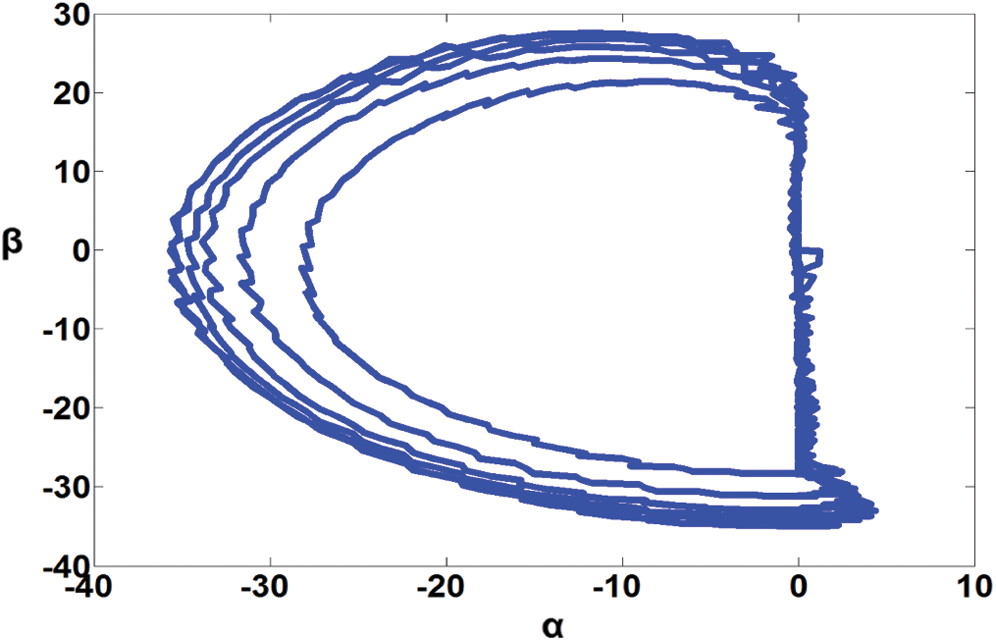
Figure 7: Nonlinear behavior in the trajectory of the grid currents in  -
- plane at Sx1 fault
Firstly, trajectory of the measured grid currents is made in the  -
- plane. The resultant phasor current of the three phase system (
 ) represents the sum of the current trajectory divided by number of data points. This trajectory is represented by a circle, which is centered in the origin at healthy case. Hence, the magnitude of the resultant will be zero at healthy condition. Whereas, the trajectory takes the shape of half-circle at any faulty switch condition with particular angle, which is dependent on the location of the faulty switch. Consequently, the resultant phasor current will have a magnitude that determines the occurrence of faulty condition when its magnitude exceeds some predefined threshold value. From another side, the angle of the resultant phasor current is dependent on the phase leg location of the faulty switch, which can give partial information about the location of the faulty switch. Fig. 8 summarizes the various trajectories of the three-phase output grid currents in the
  -
- plane for the various fault conditions. The resultant will be compared with a threshold value Ith and the difference Id will be employed for distinguishing between healthy and faulty switch conditions.
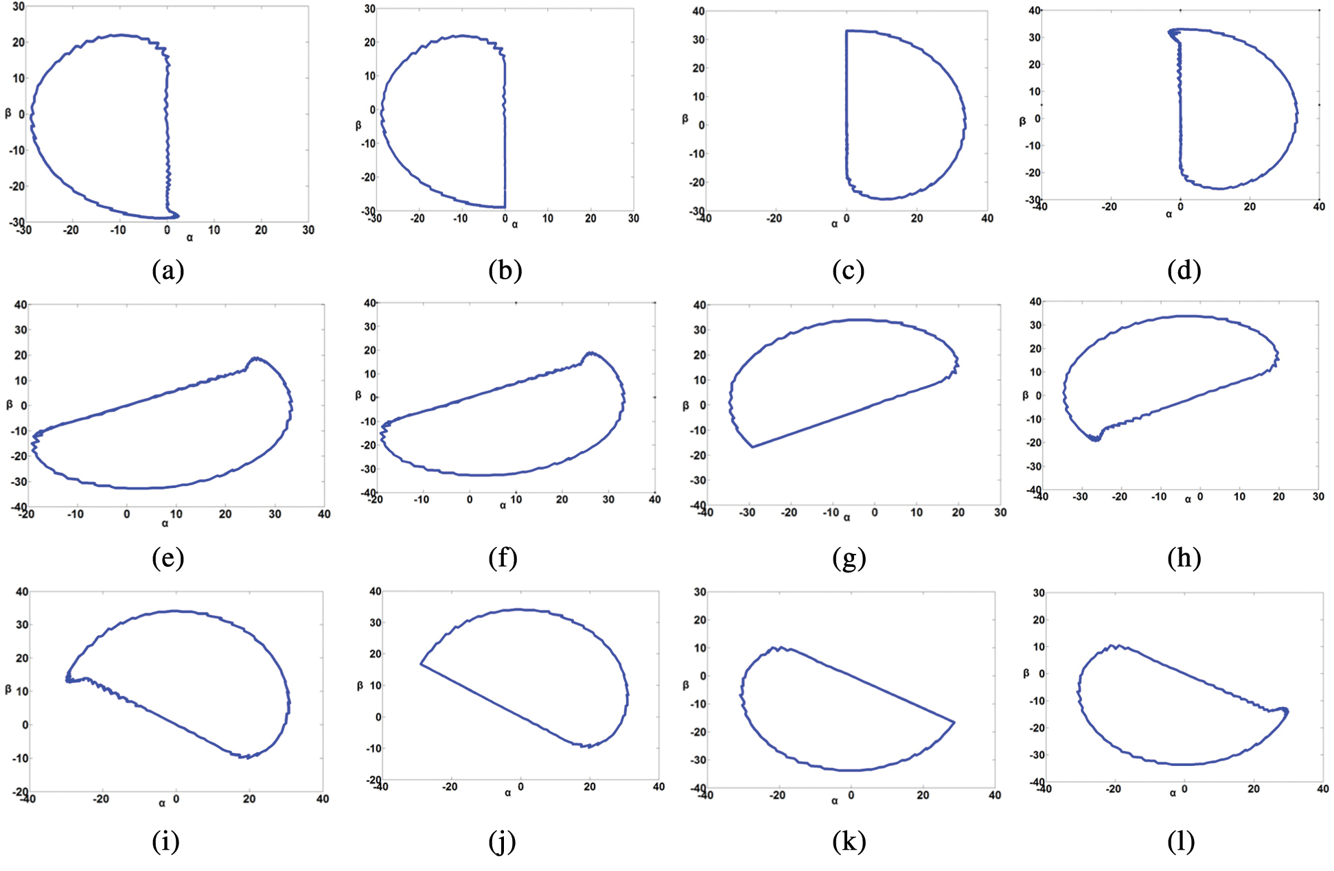
Figure 8: Trajectory of grid currents in  -
- plane in different faulty conditions. (a) Sa1 fault (b) Sa2 fault (c) Sa3 fault (d) Sa4 fault (e) Sb1 fault (f) Sb2 fault (g) Sb3 fault (h) Sb4 fault (i) Sc1 fault (j) Sc2 fault (k) Sc3 fault (l) Sc4 fault
The various faults result in different performance of the dc-link capacitor voltage related to the increase/decrease with respect to each others. Therefore, the difference between the two capacitors voltage ( ) is used in addition to current trajectory amplitude and angle to design the fuzzy rules to properly detect the location of the faulty switch. There will be three input membership functions and one output membership function to define the fault occurrence and fault switch location. The input and output membership functions of the proposed fuzzy logic fault detection method are shown in Fig. 9. Tab. 3 summarize the fuzzy bases of input and output functions to locate the fault. Where, Z denotes to zero, P to positive, N to negative, X to do not matter, and NF to no fault conditions in Tab. 3. The various rules are defined according to the response of the current trajectory and the difference between the capacitor voltages. The Mamdani fuzzy logic set is employed for implementing the proposed method. The defuzzification is performed by using Max-Min composition and the centroid of area method.
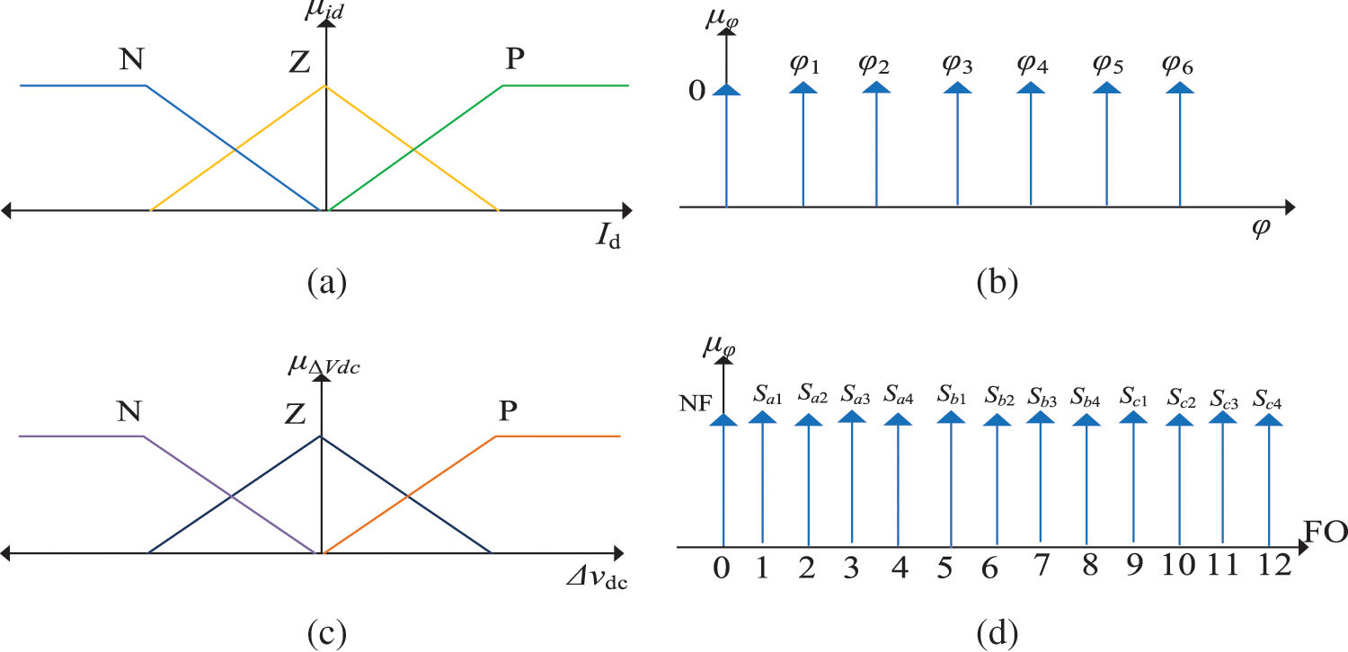
Figure 9: The input and output membership functions of the proposed fuzzy logic. (a)  (b)
(b)  (c)
(c)  (d)
(d) 
Additionally, the failure of power switches and/or diodes in the neutral point clamped topology results in the distortion of the inverter output current and unbalance of dc-link capacitor voltages. Therefore, the proposed method can be also applied to the neutral point clamped topology with the same aforementioned analysis and design method. The output signal of the proposed fault detection method is fed into fault tolerant control systems to take the proper post-fault action. Hence, continuous operation of PV inverter systems can be maintained with the help of the proposed fault detection method.
To test the feasibility and effectiveness of the proposed fault detection method, a test case study has been designed and simulated using MATLAB/SIMULINK platform. Tab. 4 summarizes the PV inverter parameters for the studied system. The open-circuit faulty condition is emulated by disconnecting the gating pulses from the power switches. Fig. 10 shows the performance of the output pole voltage at faulty switch of Sa1. It can be seen that the output pole voltage of phase a is distorted in the positive half-cycle of the output voltage. The output state P cannot be generated during this fault and the output state O is generated instead. Whereas, the other two pole voltages of phase b, and c are generated properly. It can be seen also due to the lag power factor of the inverter, some part of the positive pole voltage is not affected due to the freewheeling diode of the switch Sa1.
Table 4: The system parameters for the simulated case study
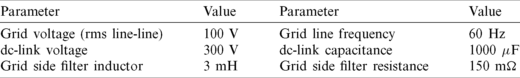
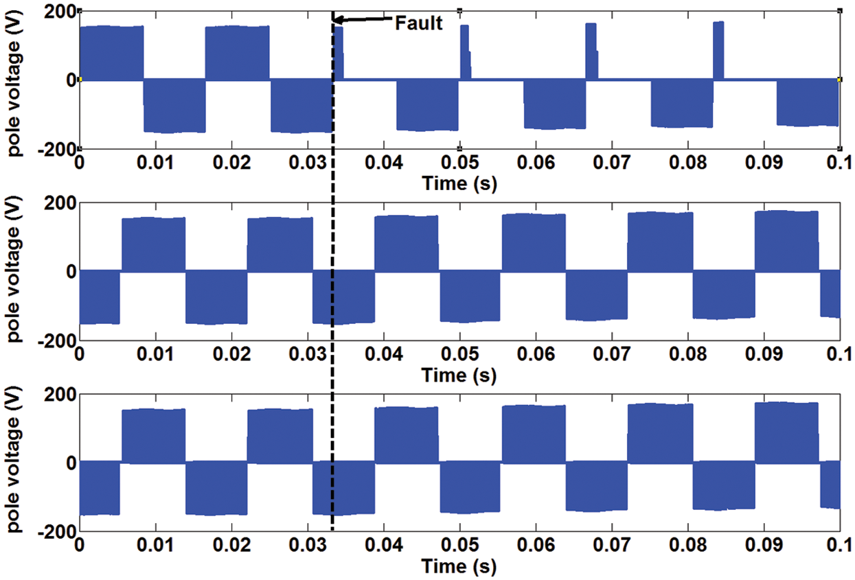
Figure 10: The simulation results of the output pole voltage at fault location in switch Sa1
The performance of the proposed fault detection method at faulty switch Sa1 is shown in Fig. 11. The output currents of the PV inverter are distorted at the faulty condition. This is a direct result from the distortion of the output pole voltage of phase leg a. The positive half-cycle of the current is eliminated due to the fault. In the proposed method, the output currents and the dc-link capacitor voltages are employed to generate the various membership inputs to the proposed fuzzy logic based fault detection method. The fuzzy logic output of the proposed method is shown in the figure. It refers to output 1 faulty condition, which denotes to the faulty switch Sa1 as described in the design of the proposed method in Tab. 3. Moreover, the output of the fuzzy logic is maintained at 0 output at no fault condition, which shows the ability of the proposed method to distinguish between the healthy and faulty conditions.
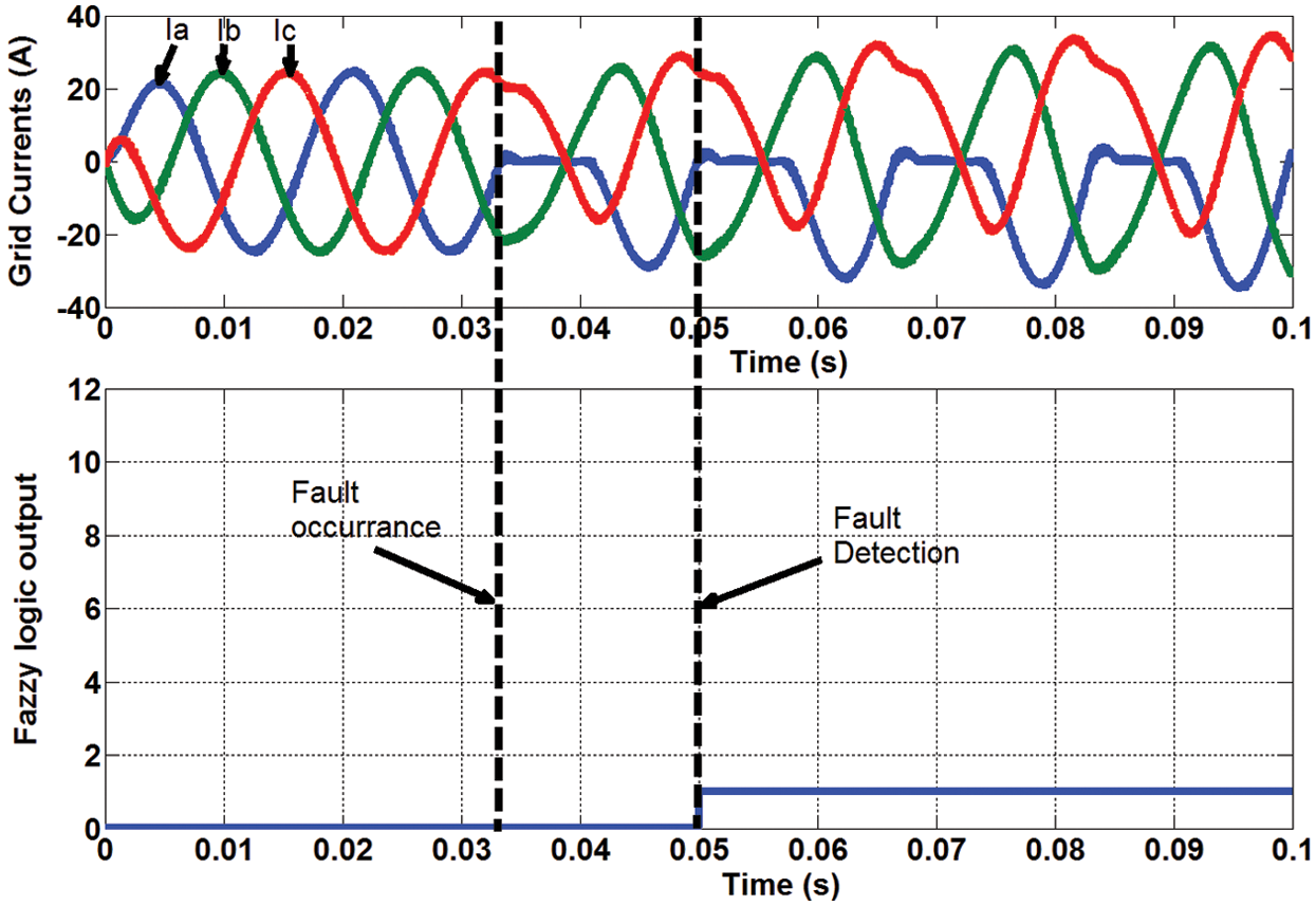
Figure 11: The simulation results of the proposed method performance at fault location in switch Sa1
The performance of the proposed method at faulty condition of Sa2 is shown in Fig. 12. It can be seen that the output current is distorted in the positive half-cycle of phase leg a. To determine the difference among the faulty case of Sa1 and Sa2, the sensed dc-link capacitor voltages are employed as inputs for the proposed method. As shown in the analysis in Fig. 6, the two faults has different effects on the dc-link capacitor voltages. The output of the proposed detection method is 2 in this case, which belongs to the faulty Sa2 condition. Therefore, the proposed method can determine the faulty condition with determining the faulty switch location. Moreover, the proposed method can detect the various faults within only a single line period.
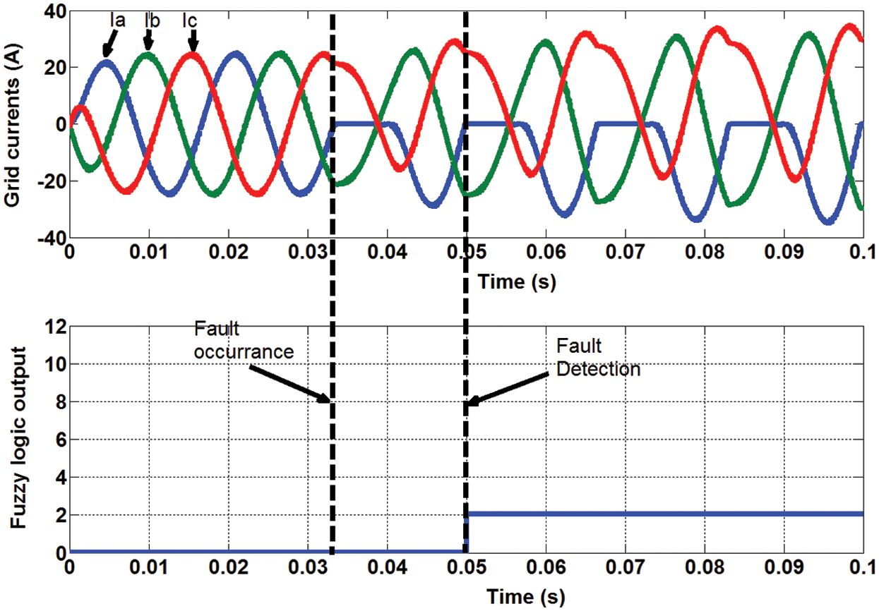
Figure 12: The simulation results of the proposed method performance at fault location in switch Sa2
Fig. 13 shows the performance of the proposed detection method at faulty switch of Sa3. The inverter operation is affected by this faulty case, and the negative half-cycle of the output current is eliminated. The current trajectory is estimated in this type of fault, and the amplitude and phase angle are fed into the proposed method. With employing the difference between capacitor voltages as input to the proposed method, the results shows the effectiveness of the proposed method to locate the faulty case and the faulty switch location. The output of the proposed fuzzy logic method denotes to the output of 3, which belongs to the switch Sa3 faulty case. It is clear the ability of the proposed fault diagnosis algorithm to detect and locate the fault within one fundamental period at various types and location of faults.
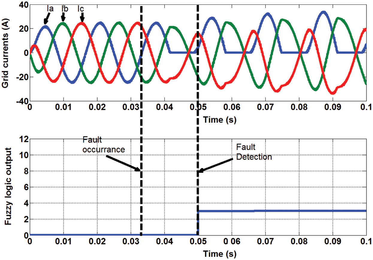
Figure 13: The simulation results of the proposed method performance at fault location in switch Sa3
An efficient fuzzy logic-based open circuit fault detection and identification method has been proposed in this paper for grid-tied PV inverters. The proposed method can deal successfully with the nonlinearities of the grid-tied PV systems and the utility grid impedance uncertainties, especially during the faults conditions. Additionally, the advantages of the proposed method are the simple implementation, no need for complex mathematical modelling, no need for large training data, and without requiring additional measurements and/or circuits. The analysis, design, and implementation of the proposed detection method are presented for the widely-used three-phase T-type three-level PV inverter topology. The performance of the measured output current and dc-link capacitor voltages are analyzed at healthy and faulty conditions for designing the fuzzy bases and for extracting the rules of the proposed fuzzy logic detection method. Furthermore, the proposed detection algorithm employs the already available measurements for the control purposed of the PV inverter. The results of the tested case study verify the superiority of the proposed detection method for detecting the various faulty conditions, and identifying the location of the faulty switch accurately.
Funding Statement: This project was supported by the Deanship of Scientific Research at Prince Sattam Bin Abdulaziz University under the research project No. 2020/01/11742.
Conflicts of Interest: The authors declare that they have no conflicts of interest to report regarding the present study.
1. E. M. Ahmed, M. Aly, A. Elmelegi, A. G. Alharbi and Z. M. Ali. (2019). “Multifunctional distributed MPPT controller for 3P4W grid-connected PV systems in distribution network with unbalanced loads,” Energies, vol. 12, no. 24, pp. 4799. [Google Scholar]
2. A. Elmelegi, M. Aly, E. M. Ahmed and A. G. Alharbi. (2019). “A simplified phase-shift PWM-based feedforward distributed MPPT method for grid-connected cascaded PV inverters,” Solar Energy, vol. 187, pp. 1–12. [Google Scholar]
3. S. M. Said, M. Aly, B. Hartmann, A. G. Alharbi and E. M. Ahmed. (2019). “SMES-based fuzzy logic approach for enhancing the reliability of microgrids equipped with PV generators,” IEEE Access, vol. 7, pp. 92059–92069. [Google Scholar]
4. M. Aly, E. M. Ahmed and M. Shoyama. (2018). “A new single phase five-level inverter topology for single and multiple switches fault tolerance,” IEEE Transactions on Power Electronics, vol. 33, no. 11, pp. 9198–9208. [Google Scholar]
5. M. Aly, E. M. Ahmed and M. Shoyama. (2017). “Thermal and reliability assessment for wind energy systems with DSTATCOM functionality in resilient microgrids,” IEEE Transactions on Sustainable Energy, vol. 8, no. 3, pp. 953–965. [Google Scholar]
6. K. Ma, D. Zhou and F. Blaabjerg. (2015). “Evaluation and design tools for the reliability of wind power converter system,” Journal of Power Electronics, vol. 15, no. 5, pp. 1149–1157. [Google Scholar]
7. M. Aly, E. Ahmed and M. Shoyama. (2017). “Developing new lifetime prolongation SVM algorithm for multilevel inverters with thermally-aged power devices,” IET Power Electronics, vol. 10, no. 15, pp. 2248–2256. [Google Scholar]
8. J. Rodriguez, J. S. Lai and F. Z. Peng. (2002). “Multilevel inverters: A survey of topologies, controls, and applications,” IEEE Transactions on Industrial Electronics, vol. 49, no. 4, pp. 724–738. [Google Scholar]
9. M. Aly, G. M. Dousoky and M. Shoyama. (2015). “Design and validation of SVPWM algorithm for thermal protection of T-type three-level inverters,” in 2015 IEEE Int. Telecommunications Energy Conf., Osaka, Japan, pp. 1074–1079. [Google Scholar]
10. M. Aly, G. M. Dousoky and M. Shoyama. (2016). “An overheating-tolerant space vector modulation algorithm for multilevel inverters,” IEEJ Transactions on Electrical and Electronic Engineering, vol. 11, no. S2, pp. S75–S83. [Google Scholar]
11. M. Aly, E. M. Ahmed and M. Shoyama. (2017). “A new real-time perfect condition monitoring for high-power converters,” in 2017 IEEE 3rd Int. Future Energy Electronics Conf. and ECCE Asia, Kaohsiung, Taiwan, pp. 1473–1477. [Google Scholar]
12. K. Ma, M. Liserre and F. Blaabjerg. (2014). “Operating and loading conditions of a three-level neutral-point-clamped wind power converter under various grid faults,” IEEE Transactions on Industry Applications, vol. 50, no. 1, pp. 520–530. [Google Scholar]
13. U. M. Choi, F. Blaabjerg and K. B. Lee. (2015). “Reliability improvement of a T-type three-level inverter with fault-tolerant control strategy,” IEEE Transactions on Power Electronics, vol. 30, no. 5, pp. 2660–2673. [Google Scholar]
14. J.-H. Choi, S. Kim, D. S. Yoo and K. H. Kim. (2015). “A diagnostic method of simultaneous open-switch faults in inverter-fed linear induction motor drive for reliability enhancement,” IEEE Transactions on Industrial Electronics, vol. 62, no. 7, pp. 4065–4077. [Google Scholar]
15. U. M. Choi, K. B. Lee and F. Blaabjerg. (2014). “Diagnosis and tolerant strategy of an open-switch fault for T-type three-level inverter systems,” IEEE Transactions on Industry Applications, vol. 50, no. 1, pp. 495–508. [Google Scholar]
16. M. Trabelsi, M. Boussak and M. Benbouzid. (2017). “Multiple criteria for high performance real-time diagnostic of single and multiple open-switch faults in ac-motor drives: Application to IGBT-based voltage source inverter,” Electric Power System Research, vol. 144, pp. 136–149. [Google Scholar]
17. H. W. Sim, J. S. Lee and K. B. Lee. (2016). “Detecting open-switch faults: Using asymmetric zero-voltage switching states,” IEEE Industry Applications Magazine, vol. 22, no. 2, pp. 27–37. [Google Scholar]
18. S. Karimi, P. Poure and S. Saadate. (2009). “Fast power switch failure detection for fault tolerant voltage source inverters using FPGA,” IET Power Electronics, vol. 2, no. 4, pp. 346–354. [Google Scholar]
19. Z. Li, H. Ma, Z. Bai, Y. Wang and B. Wang. (2018). “Fast transistor open-circuit faults diagnosis in grid-tied three-phase VSIs based on average bridge arm pole-to-pole voltages and error-adaptive thresholds,” IEEE Transactions on Power Electronics, vol. 33, no. 9, pp. 8040–8051. [Google Scholar]
20. U. M. Choi, H. G. Jeong, K. B. Lee and F. Blaabjerg. (2012). “Method for detecting an open-switch fault in a grid-connected NPC inverter system,” IEEE Transactions on Power Electronics, vol. 27, no. 6, pp. 2726–2739. [Google Scholar]
21. H. W. Sim, J. S. Lee and K. B. Lee. (2014). “A detection method for an open-switch fault in cascaded H-bridge multilevel inverters,” in 2014 IEEE Energy Conversion Congress and Exposition, Pittsburgh, Pennsylvania, USA, pp. 2101–2106. [Google Scholar]
22. N. Raj, A. Anand, A. Riyas, G. Jagadanand and S. George. (2016). “A novel open-transistor fault detection method in symmetric cascaded H-bridge multilevel inverter,” in 2016 IEEE Int. Conf. on Power Electronics, Drives and Energy Systems, Trivandrum, India, pp. 1–6. [Google Scholar]
23. J. H. Lee, J. S. Lee and K. B. Lee. (2016). “A fault detection method in cascaded H-bridge multilevel inverter,” in 2016 IEEE Int. Conf. on Power and Energy, Melaka, Malaysia, pp. 473–478. [Google Scholar]
24. D. Xie and X. Ge. (2019). “A state estimator-based approach for open-circuit fault diagnosis in single-phase cascaded H-bridge rectifiers,” IEEE Transactions on Industry Applications, vol. 55, no. 2, pp. 1608–1618. [Google Scholar]
25. S. Khomfoi and L. M. Tolbert. (2007). “Fault diagnostic system for a multilevel inverter using a neural network,” IEEE Transactions on Power Electronics, vol. 22, no. 3, pp. 1062–1069. [Google Scholar]
26. S. Kiranyaz, A. Gastli, L. Ben-Brahim, N. Al-Emadi and M. Gabbouj. (2019). “Real-time fault detection and identification for MMC using 1-D convolutional neural networks,” IEEE Transactions on Industrial Electronics, vol. 66, no. 11, pp. 8760–8771. [Google Scholar]
27. F. Wu, J. Sun, D. Zhou, Y. Liu, T. Geng et al. (2020). , “Simplified fourier series based transistor open-circuit fault location method in voltage-source inverter fed induction motor,” IEEE Access, vol. 8, pp. 83953–83964. [Google Scholar]
28. I. Jlassi, J. O. Estima, S. K. El Khil, N. M. Bellaaj and A. J. M. Cardoso. (2017). “A robust observer-based method for IGBTs and current sensors fault diagnosis in voltage-source inverters of PMSM drives,” IEEE Transactions on Industry Applications, vol. 53, no. 3, pp. 2894–2905. [Google Scholar]
29. S. H. Kim, D. Y. Yoo, S. W. An, Y. S. Park, J. W. Lee et al. (2020). , “Fault detection method using a convolution neural network for hybrid active neutral-point clamped inverters,” IEEE Access, vol. 8, pp. 140632–140642. [Google Scholar]
30. X. Qu, B. Duan, Q. Yin, M. Shen and Y. Yan. (2018). “Deep convolution neural network based fault detection and identification for modular multilevel converters,” in 2018 IEEE Power & Energy Society General Meeting, Portland, Oregon, USA, pp. 1–5. [Google Scholar]
31. T. Wang, H. Xu, J. Han, E. Elbouchikhi and M. E. H. Benbouzid. (2015). “Cascaded H-bridge multilevel inverter system fault diagnosis using a PCA and multiclass relevance vector machine approach,” IEEE Transactions on Power Electronics, vol. 30, no. 12, pp. 7006–7018. [Google Scholar]
32. S. Khomfoi and L. M. Tolbert. (2007). “Fault diagnosis and reconfiguration for multilevel inverter drive using AI-based techniques,” IEEE Transactions on Industrial Electronics, vol. 54, no. 6, pp. 2954–2968. [Google Scholar]
33. R. Hari Kumar, V. P. Mini and N. Mayadevi. (2019). “Fuzzy intelligent system for detection of multiple switch open fault in induction motor drive system,” in 2019 IEEE 4th Int. Conf. on Condition Assessment Techniques in Electrical Systems, Chennai, India, pp. 1–5. [Google Scholar]
34. F. Zidani, D. Diallo, M. E. H. Benbouzid and R. Nait-Said. (2008). “A fuzzy-based approach for the diagnosis of fault modes in a voltage-fed PWM inverter induction motor drive,” IEEE Transactions on Industrial Electronics, vol. 55, no. 2, pp. 586–593. [Google Scholar]
35. D. Zhou and Y. Tang. (2019). “A model predictive control-based open-circuit fault diagnosis and tolerant scheme of three-phase AC-DC rectifiers,” IEEE Journal of Emerging and Selected Topics in Power Electronics, vol. 7, no. 4, pp. 2158–2169. [Google Scholar]
36. M. Chai, N. B. Y. Gorla and S. K. Panda. (2020). “Fault detection and localization for cascaded H-bridge multilevel converter with model predictive control,” IEEE Transactions on Power Electronics, vol. 35, no. 10, pp. 10109–10120. [Google Scholar]
37. U. M. Choi, H. H. Lee and K. B. Lee. (2013). “Simple neutral-point voltage control for three-level inverters using a discontinuous pulse width modulation,” IEEE Transactions on Energy Conversion, vol. 28, no. 2, pp. 434–443. [Google Scholar]
 | This work is licensed under a Creative Commons Attribution 4.0 International License, which permits unrestricted use, distribution, and reproduction in any medium, provided the original work is properly cited. |