DOI:10.32604/cmc.2021.015673
| Computers, Materials & Continua DOI:10.32604/cmc.2021.015673 | |
| Article |
Improved Hybrid Beamforming for mmWave Multi-User Massive MIMO
1Department of Information and Communication Engineering and Convergence Engineering for Intelligent Drone, Sejong University, Seoul, 05006, Korea
2Department of Electrical Engineering, Sejong University, Seoul, 05006, Korea
*Corresponding Author: Hyoung-Kyu Song. Email: songhk@sejong.ac.kr
Received: 15 November 2020; Accepted: 24 December 2020
Abstract: Massive multiple input multiple output (MIMO) has become essential for the increase of capacity as the millimeter-wave (mmWave) communication is considered. Also, hybrid beamforming systems have been studied since full-digital beamforming is impractical due to high cost and power consumption of the radio frequency (RF) chains. This paper proposes a hybrid beamforming scheme to improve the spectral efficiency for multi-user MIMO (MU-MIMO) systems. In a frequency selective fading environment, hybrid beamforming schemes suffer from performance degradation since the analog precoder performs the same precoding for all subcarriers. To mitigate performance degradation, this paper uses the average channel covariance matrix for all subcarriers and considers an iterative algorithm to design analog precoder using approximation techniques. The analog precoder is iteratively updated for each column until it converges. The proposed scheme can reduce errors in the approximating process of the overall spectral efficiency. This scheme can be applied to fully-connected and partially-connected structures. The simulation results show that spectral efficiency performance for the proposed scheme is better than the conventional schemes. The proposed scheme can achieve similar performance with full-digital beamforming by using a sufficiently large number of RF chains. Also, this paper shows that the proposed scheme outperforms other schemes in the frequency selective fading environment. This performance improvement can be achieved in both structures.
Keywords: Hybrid precoding; massive MIMO; MU-MIMO; mmwave; frequency selective fading
Massive MIMO is the key solution in future 5G wireless networks to increase system capacity and data rates [1,2]. The short wavelength of the mmWave systems allows more antenna elements to be packed in the same physical dimension, thus enabling the implementation of a large-scale array. Large-scale array antennas can provide significant beamforming gains to combat the path loss and to achieve spectral efficiency via spatial multiplexing. However, it requires a large number of RF chains. A large number of RF chains render the conventional full-digital beamforming schemes impractical, due to the associated high cost and energy consumption [3,4]. To alleviate this problem, hybrid beamforming schemes have been proposed where only a limited number of RF chains can drive large-scale antenna array. Hybrid beamforming structure is consisted of a phase-shifters (PSs) based analog precoder in RF domain and low-dimensional digital precoder in baseband. Hybrid precoding algorithms for single-user MIMO (SU-MIMO) systems have been proposed in [5–7]. The orthogonal matching pursuit (OMP) was presented in [5] by exploiting the sparse nature of mmWave channels. The work in [6] sought to minimize the performance gap with the full-digital beamforming by employing an alternating minimization algorithm based on manifold optimization. Sohrabi et al. [7,8] proposed a heuristic hybrid precoding algorithm for SU-MIMO and multi-user multiple input single output (MU-MISO) system by optimizing analog precoder with fixed digital precoder in. Multi-user cases have been introduced in [7–13]. The authors in [10,11] considered MU-MIMO system, where analog precoder is designed such that the approximated upper-bound of spectral efficiency is maximized.
There are two structures of hybrid beamforming according to different mapping strategies from RF chains to antennas. Fully-connected structure can achieve high beamforming gain since each RF chain is connected to all antennas. However, this structure causes high hardware complexity and power consumption due to the large number of PS. To alleviate this problems, partially-connected structures were proposed in [10–15], where each RF chain is connected to only a subset of antennas.
One of the main challenges in hybrid beamforming design is to achieve a similar spectral efficiency with the performance of full-digital beamforming. However, there are hardware constraints that degrade performance in a hybrid beamforming system. The optimization of analog precoder is considered as very hard problem with satisfying hardware constraints. Also, the frequency selective fading channel is more challenging since analog precoder is designed equally for the entire band. Hybrid precoding algorithms for wideband systems are very important issue in mmWave communication. Recently, several works have been studied to alleviate the performance degradation from frequency selectivity in [8,12,16,17].
For the performance improvement, this paper proposes an iterative hybrid precoding scheme that can be applied to both fully-connected and partially-connected structures. The proposed scheme derives an approximated upper-bound of spectral efficiency which is used as the objective function of analog precoding matrix optimization. To obtain a solution, proposed scheme divides the problem into a series of convex sub-problems that are updated iteratively until convergence is achieved. Digital precoder eliminates the inter-user interference (IUI) by using conventional ZF precoding for the effective channel. The schemes in [7,10,11] have similar mathematical formulas and approximated method to design analog precoder in hybrid beamforming system. However, the methods in [10,11] have a large approximation error compared to the proposed scheme. The proposed scheme can reduce the approximation error by using the inequality of positive definite matrix in the process of obtaining the upper bound of spectral efficiency. And the similar mathematical formula in [7] was derived for SU-MIMO system in flat fading channel. Also, the scheme for MU-MIMO was proposed in [7]. The scheme in [7] can have a good performance in flat fading, but if the selectivity is increased, the performance is decreased considerably. This paper proposes a mathematical formula extended to the MU-MIMO system in a frequency selective fading environment. This paper shows improved spectral efficiency of the proposed scheme compared to conventional schemes in frequency selective fading channel.
This section expresses system model for conventional hybrid beamforming schemes. A block diagram of the system is given in Fig. 1. The left side represents the base station (BS) and the right side represents user terminals.
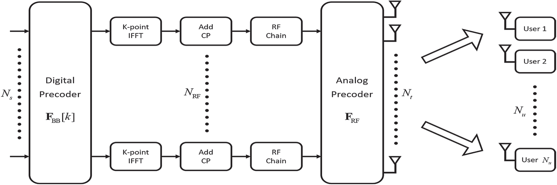
Figure 1: A block diagram of the massive MU-MIMO system with hybrid beamforming architecture
This paper considers mmWave multi-user massive MIMO hybrid beamforming system. Base station with Nt antennas and  RF chains sends Ns independent data streams. The total number of users with single-antenna is Nu. It is assumed that
 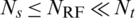 and Ns = Nu. And then the transmitted signals at each subcarrier
  can be written as follows:

where 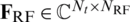 is analog precoder for all subcarriers,
 is digital precoder of the kth subcarrier for Nu users and
  is the data stream for the kth subcarrier with
  . Therefore, the received signal of user u at the kth subcarrier can be written as follows:

where  is channel matrix at the kth subcarrier, and
  represents the additive white Gaussian noise (AWGN).
2.2 Structure of Hybrid Beamforming
According to the mapping from RF chains to antennas, hybrid beamforming architectures can be categorized into fully-connected and partially-connected structures. Figs. 2a and 2b show hybrid beamforming structures for fully-connected and partially-connected, respectively.
In a fully-connected structure, each RF chain is connected to all antennas using a network of PSs. Then, fully-connected structure can be expressed as follows:

where  is the ith column vector with unit modulus elements.
Unlike the fully-connected structure, in a partially-connected structure, each of the  RF chain is connected to
  number of sub-arrays as shown in Fig. 2b. Therefore, analog precoder for partially-connected structure can be expressed as follows:
where each column vector  satisfies the constant modulus constraint.
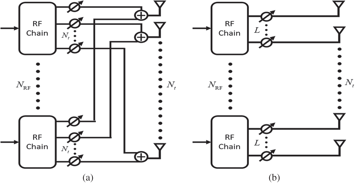
Figure 2: (a) Fully-connected structure, (b) partially-connected structure
MmWave propagation is expected to have limited scattering. In this paper, mmWave propagation environment is modeled as a geometric channel with Nc scattering clusters and Nsc scatterers within each cluster. Therefore, the channel vector for u user at subcarrier k is given as follows [8]:

where  is a normalization factor,
  is proportional to the phase shift in the cth cluster and
 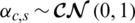 is the complex gain for the sth scatter in the cth cluster.
  represents the transmit antennas array response vector,
  is azimuth angle of departure (AOD). Then, the array response vector of the uniform linear array (ULA) with Nt transmit antennas is modeled as follows:

where d and  are the antenna spacing and signal wavelength.
In this paper, the perfect channel state information (CSI) is assumed.
This paper considers the problem of the hybrid beamforming design to maximize the overall spectral efficiency under a constant modulus constraint (7b) and transmit power constraint (7a) for each subcarrier. Then the objective function can be expressed as follows:

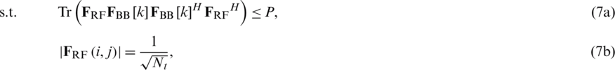
where 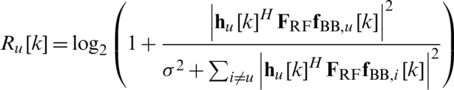 is spectral efficiency of user u at the kth subcarrier. P is maximal transmit power at the BS,
  is variance of the AWGN and
  is the
  th element of
  .
.
3 Hybrid Beamforming Scheme for Multi-User Massive MIMO System
In this section, the design of digital and analog precoders for multi-user massive MIMO systems is considered. Then, the comparison between conventional schemes and proposed scheme is described.
3.1 Design of Digital Precoder
In this paper, digital precoder is designed by using conventional ZF precoding to eliminate inter-user interference. The effective channel matrix for subcarrier k is denoted as 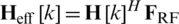 . For fixed analog precoder, normalized digital precoding matrix for subcarrier k is as follows:

where 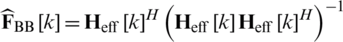 . Power constraint (7a) can be satisfied due to the normalized digital precoding matrix (8). Then, (7) can be approximated by using properties of ZF precoding in (8) as follows:
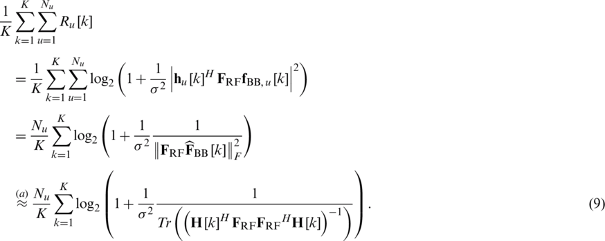
The proof of the  in (9) is provided in Appendix A. Finally, the objective function (7) can be restated as a problem that maximizes (9).
3.2.1 Fully-Connected Structure
This paper proposes a scheme to design an analog precoder to maximize (9). However, (9) is difficult to find an optimal solution since analog precoding matrix  exists inside the inverse matrix. To solve this problem, it has to be converted through approximation techniques. Then, Eq. (9) can be converted as follows:


where 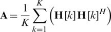 is the average channel covariance matrix for all subcarriers. The proof of (10) is given in Appendix B. Due to the constraint of the analog precoder, (10) is still difficult to solve. The objective function (10) needs to be manipulated for efficient optimization. Finally, (10) can be expressed by using the determinant property in [18]. It is shown in Appendix C as follows:

where  is positive semi-definite matrix,
  is the sub-matrix of
  that the lth column is removed, and
  is the lth column of
  . Since
  is independent of
  , objective function (10) can be converted into sub-objective function (12) for each column.


Then, the column iterative algorithm is used to maximize the sub-objective function (12). Each column of analog precoder is repeatedly updated to  until it converges. However, the components in analog precoder have to satisfy the constraint (12a). Since the analog precoder consists of PSs, the lth column of analog precoder can be expressed as follows:

The objective function (10) increases as the  is updated. Finally, proposed algorithm is converged. The proposed algorithm for design of hybrid precoders is summarized as follows:
Step 1: Input channel matrix  .
.
Step 2: Generate random initial matrix  that satisfies the constant modulus constraint.
Step 3: Calculate average channel covariance matrix for all subcarriers 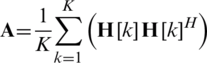 .
.
Step 4: Repeat the following process  times (
 ),
),
Calculate positive semi-definite matrix 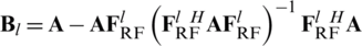 ,
,
Set 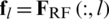 ,
,
Update lth column of analog precoder 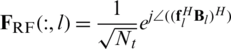 .
.
Step 5: Go to Step 4 until  converges.
Step 6: Repeat the following process K times ( ),
),
Calculate the digital precoder  for each subcarrier according to (8).
Step 7: Output analog and digital precoder  .
.
3.2.2 Partially-Connected Structure
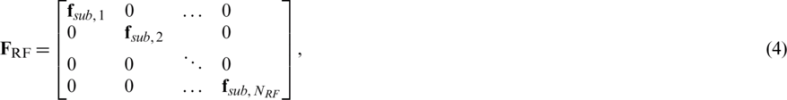
When partially-connected structures are considered, analog precoder  is represented as a block matrix consisting of vectors of length L as shown in (4). Consequently, the sub-objective function (12) can be expressed as follows:


where  is the lth column vector of
  as shown in (4),
  is the lth sub-block matrix of
  . It is given as follows:

Then, the lth column of analog precoder can be obtained through the same process as the fully-connected structure.  is as follows:

For the partially-connected structure, the precoder design is performed through a similar procedure based on the aforementioned algorithm.
3.2.3 Comparison with Conventional Schemes
This subsection compares the proposed scheme and the conventional schemes. Conventional schemes in [10,11] also use approximation techniques similar to Appendix B to obtain the upper bound of spectral efficiency. However, the approximation of conventional schemes is performed before  in Appendix B. This approach can lead to large approximation errors. Then, conventional schemes aim to maximize (17) by performing optimization.

The optimal solution to maximize (17) can be obtained through singular value decomposition (SVD) of the average channel covariance matrix for all subcarriers. However, due to constant modulus constraint (7b), analog precoder cannot use the optimal matrix. Therefore, analog precoder in [10] is designed by using phase of optimal matrix where optimal matrix is right singular matrix corresponding to the largest  singular values of
 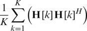 . In [11], the iterative method is proposed to maximize (17). This method considers the minimization of the off-diagonal components while the diagonal components of (17) are maximized. Conventional schemes show good performance, but there is a performance loss due to an approximation error. The performance comparison with the proposed scheme is represented in Section 4.
Simulation results are presented to evaluate the performance of the proposed scheme for multi-user hybrid beamforming systems. In this section, the proposed scheme is compared with full-digital beamforming and conventional hybrid beamforming schemes. All simulations are performed for the MU-MIMO hybrid beamforming systems. The simulated mmWave channel adopts Nc = 5 clusters and 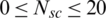 scatterers. The number of RF chains is
  .
.
Figs. 3 and 4 show the spectral efficiency of the hybrid beamforming schemes for the fully-connected and partially-connected structure, respectively. Figs. 3 and 4 consider Nt = 16 transmit antennas and Nu = 4 single-antenna users. In Fig. 3, proposed scheme can achieve similar performance with full-digital beamforming. Also, proposed scheme shows improved spectral efficiency performance compared to [10,11] since a difference in approximation error occurs. In flat fading environment, hybrid beamforming scheme in [7] shows near-optimal performance for MU-MIMO system. However, Fig. 3 shows that the scheme in [7] has a large performance degradation in a frequency selective fading environment. The scheme in [7] is implemented by using the average matrix of channels for all subcarriers. Fig. 4 shows the spectral efficiency performance of the partially-connected hybrid beamforming schemes. Each RF chain is connected to two transmit antennas where L = 2. As shown in Fig. 4, the performance of the partially-connected structure is degraded compared to the fully-connected structure since the beamforming gain is reduced. In this structure, proposed scheme has a slight improvement in spectral efficiency performance compared to other schemes.
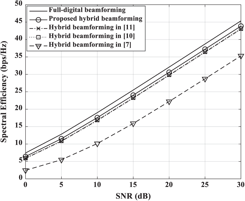
Figure 3: Spectral efficiency vs. SNR for fully-connected beamforming schemes in a 4 single-antenna user MIMO system with Nt = 16
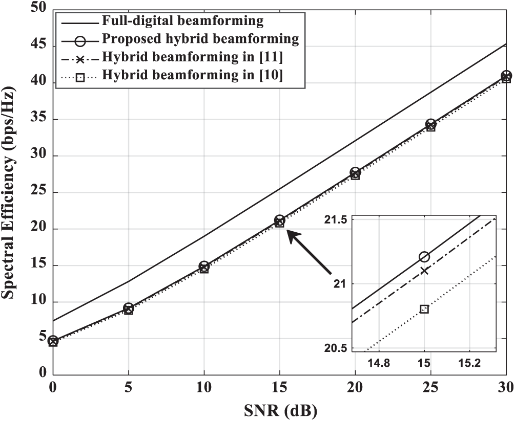
Figure 4: Spectral efficiency vs. SNR for partially-connected beamforming schemes in a 4 single-antenna user MIMO system with Nt = 16
Fig. 5 shows the spectral efficiency for number of clusters when Nt = 64 , Nu = 8 ,  dB. As the number of clusters increases, frequency selectivity increases. Frequency selective fading degrades the spectral efficiency of hybrid beamforming since analog precoder cannot be designed for each subcarrier. In Fig. 5, the performance of all schemes gradually converges as the number of clusters increases. The scheme in [7] designed for a flat fading environment suffers significant performance degradation due to frequency selective fading. As the cluster increases, the performance of proposed scheme is also degraded, but it is better than other schemes in the frequency selective fading environment.
Figure 5: Spectral efficiency vs. the number of clusters for fully-connected beamforming schemes in a 8 single-antenna user MIMO system where Nt = 64 ,  dB
dB
Fig. 6 shows the spectral efficiency for number of RF chains Nt = 64 , Nu = 8,  dB. In Fig. 6, full-digital beamforming represents the fixed performance at
  . It is shown that all schemes can achieve performance approaching full-digital beamforming as the number of RF chains increases. Also, proposed scheme can achieve near full-digital beamforming performance using RF chains of half the number of transmitting antennas. This is because the proposed scheme can obtain the large beamforming gain through the increase of the RF chain. Other schemes have less performance improvement as the RF chain increases compared to the proposed scheme. Especially, hybrid beamforming in [7] shows poor performance even if the number of RF chains increases where
  .
.
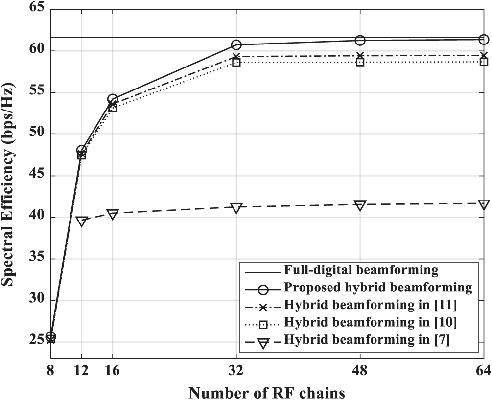
Figure 6: Spectral efficiency vs. the number of RF chains for fully-connected beamforming schemes in a 8 single-antenna user MIMO system where Nt = 64 , Nc = 5 ,  dB
dB
This paper proposes an enhanced hybrid beamforming method for multi-user massive MIMO systems. The proposed scheme can be applied to fully-connected and partially-connected structure. This scheme can improve performance by reducing approximation error in the process of approximating the system spectral efficiency. It is shown that the proposed scheme for both structures shows better performance compared to other schemes. Due to the limitations of the analog precoder, frequency selectivity causes significant performance degradation. Nevertheless, the proposed scheme achieves good performance in a frequency selective fading environment that the number of clusters increases. Also, the proposed scheme can achieve near full-digital beamforming performance using RF chains of half the number of transmitting antennas due to large beamforming gain.
Funding Statement: This work was supported in part by Institute for Information & communications Technology Promotion (IITP) grant funded by the Korea government (MSIT) (No. 2017-0-00217, Development of Immersive Signage Based on Variable Transparency and Multiple Layers), and in part by the Basic Science Research Program through the National Research Foundation of Korea (NRF) funded by the Ministry of Education under Grant 2020R1A6A1A03038540.
Conflicts of Interest: The authors declare that they have no conflicts of interest to report regarding the present study.
1. Z. Pi and F. Khan. (2011). “An introduction to millimeter-wave mobile broadband systems,” IEEE Communications Magazine, vol. 49, no. 6, pp. 101–107. [Google Scholar]
2. A. L. Swindlehurst, E. Ayanoglu, P. Heydari and F. Capolino. (2014). “Millimeter-wave massive MIMO: The next wireless revolution?,” IEEE Communications Magazine, vol. 52, no. 9, pp. 56–62. [Google Scholar]
3. E. Telatar. (1999). “Capacity of multi-antenna Gaussian channels,” European Transactions on Telecommunications, vol. 10, no. 6, pp. 585–595. [Google Scholar]
4. A. Wiesel, Y. C. Eldar and S. Shamai. (2008). “Zero-forcing precoding and generalized inverses,” IEEE Transactions on Signal Processing, vol. 56, no. 9, pp. 4409–4418. [Google Scholar]
5. O. E. Ayach, S. Rajagopal, S. Abu-Surra, Z. Pi and R. W. Heath. (2014). “Spatially sparse precoding in millimeter wave MIMO systems,” IEEE Transactions on Wireless Communications, vol. 13, no. 3, pp. 1499–1513. [Google Scholar]
6. X. Yu, J. Shen, J. Zhang and K. B. Letaief. (2016). “Alternating minimization algorithms for hybrid precoding in millimeter wave MIMO systems,” IEEE Journal of Selected Topics in Signal Processing, vol. 10, no. 3, pp. 485–500. [Google Scholar]
7. F. Sohrabi and W. Yu. (2016). “Hybrid digital and analog beamforming design for large-scale antenna arrays,” IEEE Journal of Selected Topics in Signal Processing, vol. 10, no. 3, pp. 501–513. [Google Scholar]
8. F. Sohrabi and W. Yu. (2017). “Hybrid analog and digital beamforming for mmwave OFDM large-scale antenna arrays,” IEEE Journal on Selected Areas in Communications, vol. 35, no. 7, pp. 1432–1443. [Google Scholar]
9. L. Liang, W. Xu and X. Dong. (2014). “Low-complexity hybrid precoding in massive multiuser MIMO systems,” IEEE Wireless Communications Letters, vol. 3, no. 6, pp. 653–656.
10. Y. Liu and J. Wang. (2020). “Low-complexity OFDM-based hybrid precoding for multiuser massive MIMO systems,” IEEE Wireless Communications Letters, vol. 9, no. 3, pp. 263–266. [Google Scholar]
11. S. Gherekhloo, K. Ardah and M. Haardt. (2020). “Hybrid beamforming design for downlink MU-MIMO-OFDM millimeter-wave systems,” in 2020 IEEE 11th Sensor Array and Multichannel Signal Processing Workshop, Hangzhou, China, pp. 1–5. [Google Scholar]
12. S. Lee, W. S. Lee, J. H. Ro, Y. H. You and H. K. Song. (2020). “Hybrid precoding technique with iterative algorithm for MIMO-OFDM system,” IEEE Access, vol. 8, pp. 171423–171434. [Google Scholar]
13. S. J. Shim, S. Lee, W. S. Lee, J. H. Ro, J. I. Baik et al. (2020). , “Advanced hybrid beamforming technique in MU-MIMO systems,” Applied Sciences, vol. 10, no. 17, pp. 5961. [Google Scholar]
14. Z. Xu, S. Han, Z. Pan and I. Chih-Lin. (2015). “Alternating beamforming methods for hybrid analog and digital MIMO transmission,” in 2015 IEEE Int. Conf. on Communications, London, pp. 1595–1600.
15. A. Li and C. Masouros. (2017). “Hybrid precoding and combining design for millimeter-wave multi-user MIMO based on SVD,” in 2017 IEEE Int. Conf. on Communications, Paris, pp. 1–6. [Google Scholar]
16. L. Kong, S. Han and C. Yang. (2015). “Hybrid precoder for massive MIMO systems with coverage constraint,” in 2015 IEEE/CIC Int. Conf. on Communications in China - Workshops, Shenzhen, pp. 38–43. [Google Scholar]
17. A. Alkhateeb and R. W. Heath. (2016). “Frequency selective hybrid precoding for limited feedback millimeter wave systems,” IEEE Transactions on Communications, vol. 64, no. 5, pp. 1801–1818. [Google Scholar]
18. Z. Pi. (2012). “Optimal transmitter beamforming with per-antenna power constraints,” in 2012 IEEE Int. Conf. on Communications, Ottawa, ON, pp. 3779–3784. [Google Scholar]
Appendix A. The proof of (9)
The term  in
in  of (9) can be approximated as follows:

where the analog precoder typically satisfies 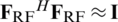 when number of transmit antennas Nt is sufficiently large [7].
Appendix B. The proof of (10)
Eq. (9) can be approximated as follows:

where  is based on Jensen’s inequality,
  and
and  are based on inequality
 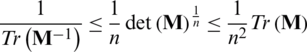 for a positive definite matrix
  . The approximation error of (19) is reduced by using property of
  . Consequently, the objective function is transformed into a problem that maximizes (10).
Appendix C. The proof of (11)
Eq. (10) can be expressed as follows:
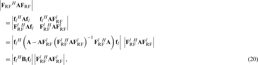
where (20) can be obtained by using property of determinant  . Then,
  is used to maximize spectral efficiency through the column iterative algorithm.
 | This work is licensed under a Creative Commons Attribution 4.0 International License, which permits unrestricted use, distribution, and reproduction in any medium, provided the original work is properly cited. |