DOI:10.32604/cmc.2021.015843
| Computers, Materials & Continua DOI:10.32604/cmc.2021.015843 | |
| Article |
Resonator Rectenna Design Based on Metamaterials for Low-RF Energy Harvesting
1Department of Electronics and Telecommunication Engineering, Faculty of Engineering, Rajamangala University of Technology Thanyaburi (RMUTT), Pathumthani, 12110, Thailand
2Department of Telecommunications Engineering, Faculty of Engineering and Architecture, Rajamangala University of Technology Isan, Nakhon Ratchasima, 30000, Thailand
3School of Telecommunication Engineering, Suranaree University of Technology, Nakhonratchasima, 30000, Thailand
*Corresponding Author: Amnoiy Ruengwaree. Email: amnoiy.r@en.rmutt.ac.th
Received: 10 December 2020; Accepted: 19 February 2021
Abstract: In this paper, the design of a resonator rectenna, based on metamaterials and capable of harvesting radio-frequency energy at 2.45 GHz to power any low-power devices, is presented. The proposed design uses a simple and inexpensive circuit consisting of a microstrip patch antenna with a mushroom-like electromagnetic band gap (EBG), partially reflective surface (PRS) structure, rectifier circuit, voltage multiplier circuit, and 2.45 GHz Wi-Fi module. The mushroom-like EBG sheet was fabricated on an FR4 substrate surrounding the conventional patch antenna to suppress surface waves so as to enhance the antenna performance. Furthermore, the antenna performance was improved more by utilizing the slotted I-shaped structure as a superstrate called a PRS surface. The enhancement occurred via the reflection of the transmitted power. The proposed rectenna achieved a maximum directive gain of 11.62 dBi covering the industrial, scientific, and medical radio band of 2.40–2.48 GHz. A Wi-Fi 4231 access point transmitted signals in the 2.45 GHz band. The rectenna, located 45
Keywords: Metamaterials; energy harvesting; rectenna; Wi-Fi; partially reflective surface; EBG
Energy is one of the factors that affects human life and helps humans live comfortably. However, energy loss is a significant problem and has a severe impact on the economic and social development of many countries [1]. Today, humans have access to alternative energy sources in various forms, such as water power [2], biomass [3], wind power [4], and solar energy [5]. Another exciting energy source is that generated when an antenna is used as a frequency receiver with a rectifier to convert AC to DC power [6,7]. Radio-frequency (RF) waves are generally spread throughout all regions of a country and is continually used in the form of electromagnetic waves, such as waves from FM radio, digital television [8], mobile phones [9], and Wi-Fi wireless transmission systems [10]. Several researchers have been interested in improving rectenna system efficiency, as shown in Fig. 1. The development process of such a system can be divided into two main parts.
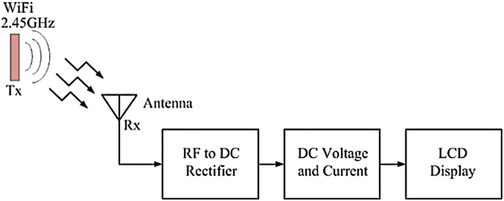
Figure 1: Process of ambient radio-frequency energy harvesting
The first part is the antenna, whereby most researchers have designed the antenna structure with a directional radiation pattern. The advantage of such a radiation pattern is that it can directly receive all of the energy in one direction at the front of the antenna [11]. In collecting energy, antennas with omnidirectional and bidirectional radiation patterns are significantly less effective [12], meaning that the energy obtained is split into several directions.
Therefore, relevant research has focused on combining an antenna with metamaterial of the EBG, which may improve the efficiency of antenna gain. An EBG metamaterial sheet has a multitude of structures according to mathematical shapes, such as rectangles, circles [13], triangles [14], I shapes [15], hexagons, Y shapes, and plus-sign shapes [16]. From this point of view, many researchers have established new structures. Examples of additional research that has been developed include following. (1) The mushroom-like EBG sheet for the installation in an antenna is applied in a square multiple-input–multiple-output (MIMO) system with a combination element that increases from 5.3 to 8.3 dB, a 63.85% rise [17]. (2) A complementary split-ring resonator antenna combined with a square grid structure in a Doppler radar system increased the gain up to 11.3 dB [18]. (3) The gains of a triangular antenna for wireless communication at the low-frequency band of 3.5 GHz and the high frequency band of 5.8 GHz are usually 1.95 and 2.16 dBi, respectively. This gain could be adjusted with an artificial magnetic conductor, which increased the triangular antenna gains to 9.37 and 6.63 dBi, respectively [19]. (4) A rectangular microstrip antenna of 7.45 GHz frequency increased the amplification to 12.31 dBi when combined with a circularly polarized (CP) plate [20]. (5) Researchers developed a structure with metamaterials laid in more than three layers and three dimensions that is called an I-shaped antenna; it is used in 5G applications at the 28 GHz frequency band. When tuned with a dual-band slotted printed circular patch, the maximum gain was 8 dB [21]. (6) A horn antenna used in 5G applications at a low frequency of 2 GHz and a high frequency of 3.5 GHz when tuned with negative-refractive-index metamaterial (NRIM) achieved maximum gains of 8.1 and 8.93 dB, respectively [22]. (7) A 9.5–13 GHz rectangle microstrip antenna, tuned with chessboard polarization conversion metasurface, had a maximum gain of 13.4 dB [23]. (8) A 37.5 GHz rectangle microstrip antenna, tuned with a printed ridge gap waveguide, had a maximum gain of 23.5 dB [24]. (9) The efficiency of a rotated Y-shaped antenna, including a mushroom-like EBG, with a directional radiation pattern, was improved from 89% to 94% by using a slotted EBG ground plane. The antenna gain increased to 8.91 dB at 38.06 GHz for a 5G cellular communication system [25]. (10) The gain increment was further studied using a 3.6 GHz microstrip patch antenna to install a
The second development part of an antenna system is focused on electronics circuit design rather than on the antenna structure. A full-wave rectifier circuit and a seven-times-voltage-boosting circuit has been designed. In this design, the system efficiency increases by 18.6% at −50 dBm. The advantage of this approach is that it can increase system efficiency by not requiring the receiver antenna to be 100% energized from the transmitted antenna [28]. This means integrating antennas in one structure with rectifier circuits, which reduce cable losses. The reduction of losses can improve energy converter efficiency by up to 83% at −15 dBm [29]. A wideband stacked patch antenna [30] is composed of a double layer of a substrate to expand bandwidth with parasitic circular patches to increase the directional gain to 6.7 dB. The antenna was designed to connect to a HSMS-2850 rectifier circuit diode. The measured peak efficiency was 63% with an input power of 0 dB. The advantage of a wideband stacked patch antenna is its low profile. However, the gain is low, resulting in a need for high input power. A bridge rectifier circuit design with a harmonic rejection filter was fabricated on a FR4 printed circuit board (PCB) and an interdigital capacitor capable of boosting the power conversion efficiency to 78.7% at 20 dBm with a rectangular double-layer antenna with a gain of 7.3 dB [31]. An antenna designed with a dipole antenna structure using a vapor-conduction technique combined with a coplanar strip-line to help adjust the impedance to suit energy harvesting had an output gain of 8.6 dB. Moreover, an AC-to-DC power converter is essentially a half-wave rectifier.
The DC-bandpass filter used in the present work consists of a Schottky HSMS-2852 high-frequency diode together with a capacitor. This filter acts to protect the power from the microwave to the reflected load, which can convert 83% of the power at −15 dBm [32]. A monopole antenna with square grooving helps adjusts the impedance match between the antenna and the full-wave rectifier circuit to transmit maximum energy. This achieved a gain of 5.6 dB. An output power converter of up to 68% at 5 dBm [33,34] was investigated in a study of a square
In this research, the two-part development of an RF energy harvesting system from the points of view of its advantages and disadvantages is proposed. The first part is focused on a directional pattern microstrip antenna [11] with an uncomplicated structure that was easy to adjust and combine with mushroom-like EBG metamaterial [16]. Square structure with a hybrid rectenna [36,37] techniques were applied to increase the gain of the receiver. The second part is to design the RF conversion circuit utilizing a full-wave rectifier circuit [28] combined with a voltage multiplier circuit to increase the voltage. This system uses the designed rectenna to receive energy at a frequency of 2.45 GHz, which is the most widely applied frequency in wireless communication in Thailand. Analysis of the antenna structure and voltage boost circuit design are discussed in Section 2. The effect of antenna design parameters and equipment on the voltage multiplier circuit is discussed in the Section 3. The comparative results of measurement and simulation are discussed in Section 4 regarding the reflective coefficients, electric field plane (E-plane), magnetic field plane (H-plane), antenna gain, and energy capture. Discussion and comparison with previous works are presented in Section 5. Conclusions are drawn in Section 6.
2 Antenna Structural Design and Rectifier Circuits
The microstrip antenna structure designed in the present work is a basic rectangle shape, as shown in Fig. 2a, which had the advantage of having an uncomplicated structure. It was easy to design with a few fine-tuning points. The electromagnetic wave was spread in a specific direction to cover the area as needed [11]. The antenna structure was designed and fabricated on a PCB made of FR4 substrate. The advantages of this PCB are the following. The structure is strong and not easily broken; it has the form of a thin sheet and is easily accessible in Thailand. It is generally used to design, develop, and build antennas [11,12]. PCB FR4 substrate maintains constant electrical conductivity throughout the sheet. Therefore, the measurement results were close to actual simulation results. The selected PCB FR4 substrate has a dielectric constant (
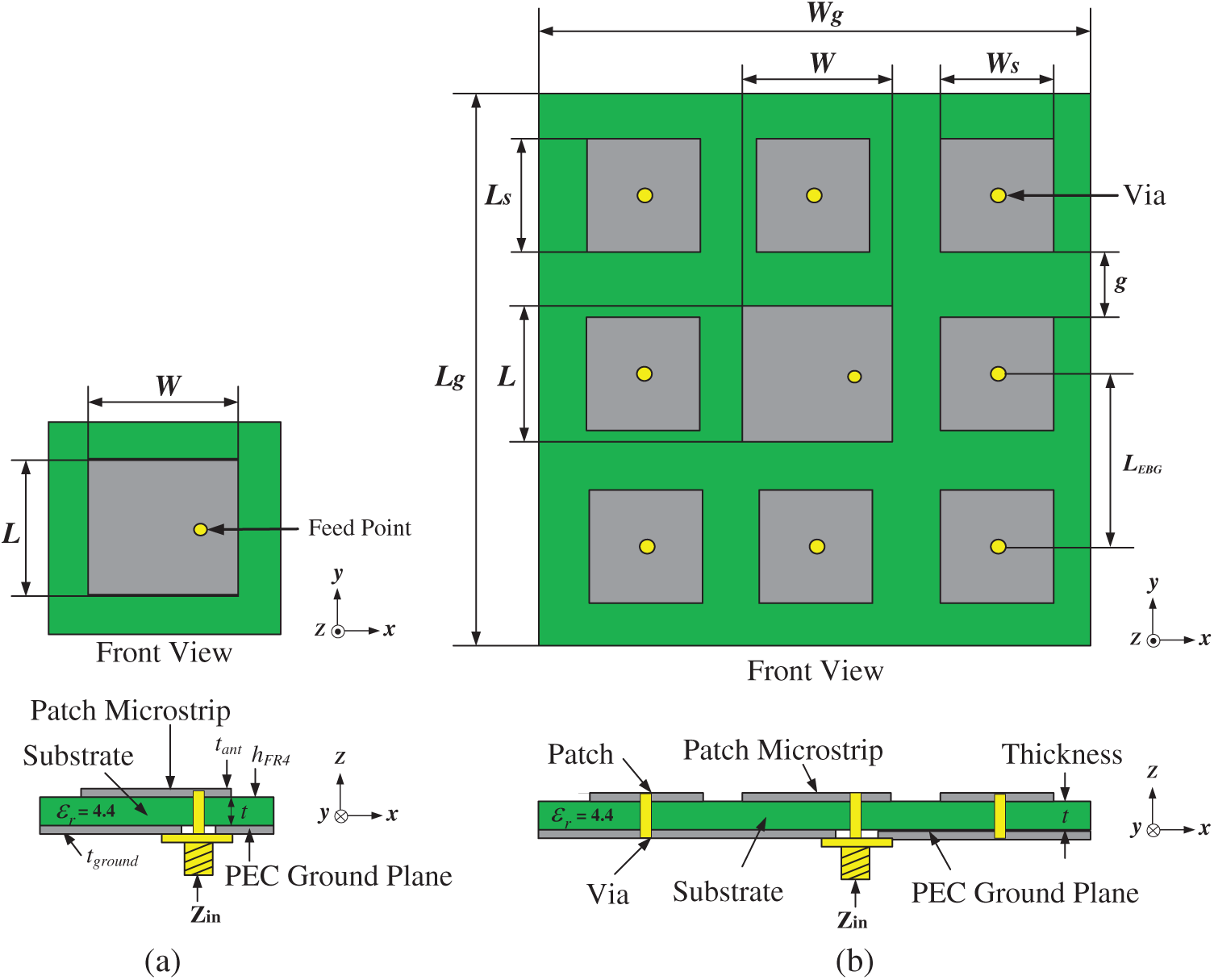
Figure 2: (a) The microstrip antenna structure based on rectangle shape (b) the g-gap space of the EBG structure
Metamaterial with an I-shaped slot structure was chosen to improve the structure of the antenna to increase the gain, as shown in Fig. 3a. The main advantage of this metamaterial structural design is simply to tune the resonance frequency. The unit cell (I-shaped slot) on the metamaterial measured
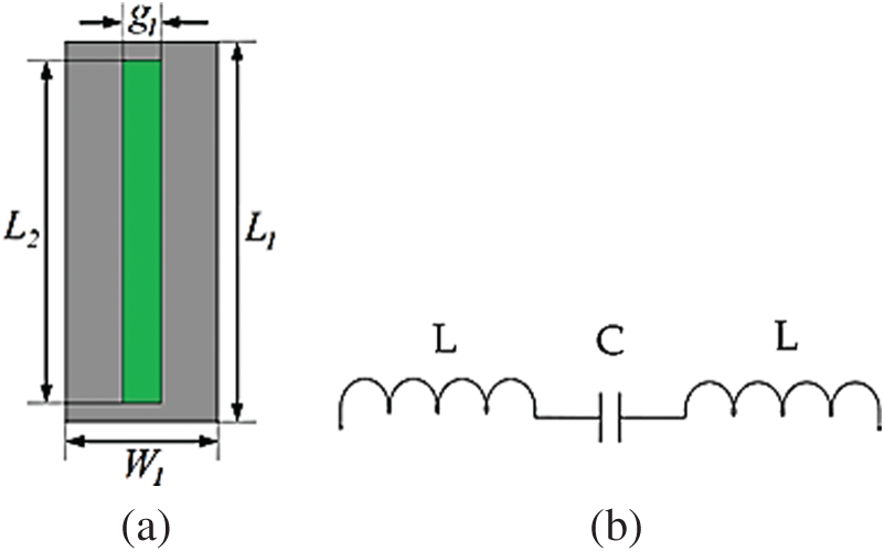
Figure 3: (a) Unit cell of I-shaped slot and (b) equivalent circuit in LC model
The structural design of the metal sheet was done on FR4 substrate. After structural adjustment, the width parameter of the metamaterial W1 was 15.30 mm (
Both L1 and L2 values had features approaching Mu- and Epsilon-Near-Zero (MENZ), i.e., MENZ material. MENZ is classified into two types. The first type is a negative value approaching zero, which allows the wave to propagate through the metamaterial structure. The second type is the positive value approaching zero, in which the metamaterial acts as the reflecting surface. In this case, the conditions of permittivity and permeability are positive values that approach zero.
Consequently, this metamaterial structure served as a reflecting surface that partly reflected the waves and partly transmitted waves through it. The metamaterial was designed to be a two-dimensional (2D) wave band gap by combining the antenna structure, as shown in Fig. 4. The height (h) between the radiator and metamaterial sheet can be calculated by Eq. (6):
where
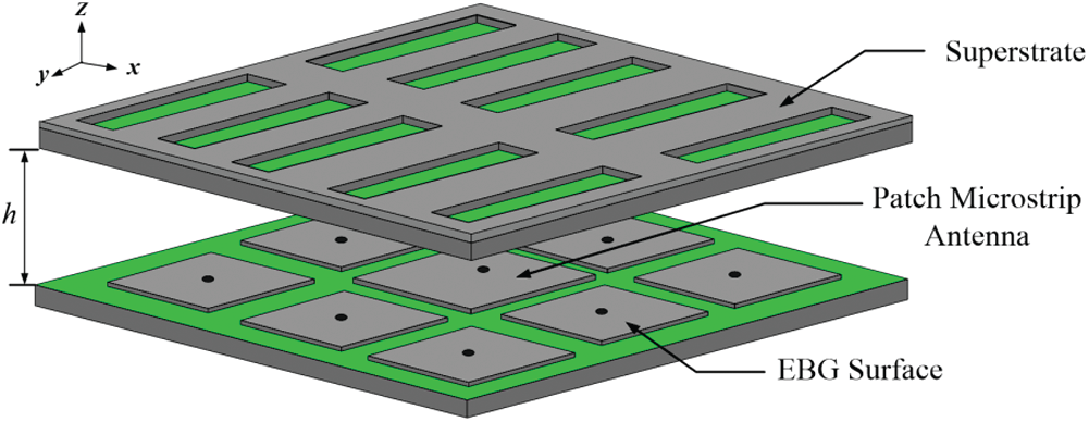
Figure 4: Prototype antenna structure
The electrical energy stored from the RF signal of the frequency band of 2.45 GHz is the AC. The full-wave rectifier circuit converts AC to DC, which, in conjunction with the Cockcroft Walton voltage multiplier circuit, increased the voltage. Diode HSMS-2850 [32] is a well-known diode used in voltage multiplier circuits of high-frequency energy-storage systems in which the diodes are attached in bulk to increase the voltage, as shown in Fig. 5. A microcontroller (PIC16F877A) was used as the processing unit to measure and display the rectenna power and voltage values, as shown in Fig. 6a, and a C language program was used to control the LCD screen display (
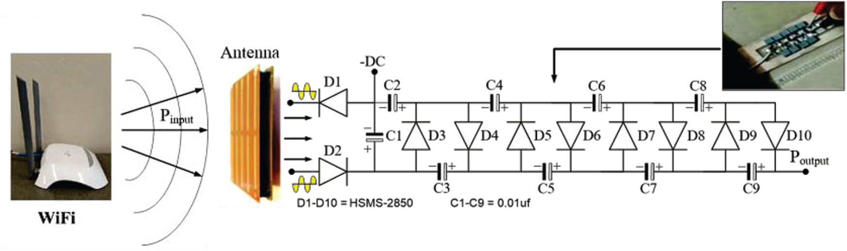
Figure 5: Connection of prototype antenna to rectifier and Cockcroft Walton voltage multiplier circuit
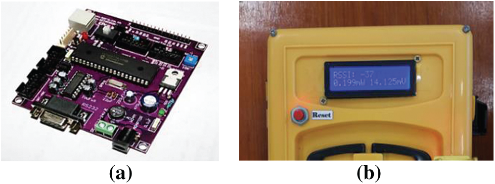
Figure 6: Rectenna power and voltage meter. (a) PIC16F877A microcontroller, (b) voltage multiplier circuit and LCD
3.1 Simulation of Antenna Design
First, the design parameters of a rectangular microstrip antenna at 2.45 GHz were calculated using Eqs. (1) and (2), as defined in Fig. 2a. It was found that the width (W) = 37.54 mm and length (L) = 28.93 mm had S11 equal to −12.65 dB, as shown in Fig. 7a. The simulation results of impedance and gain were
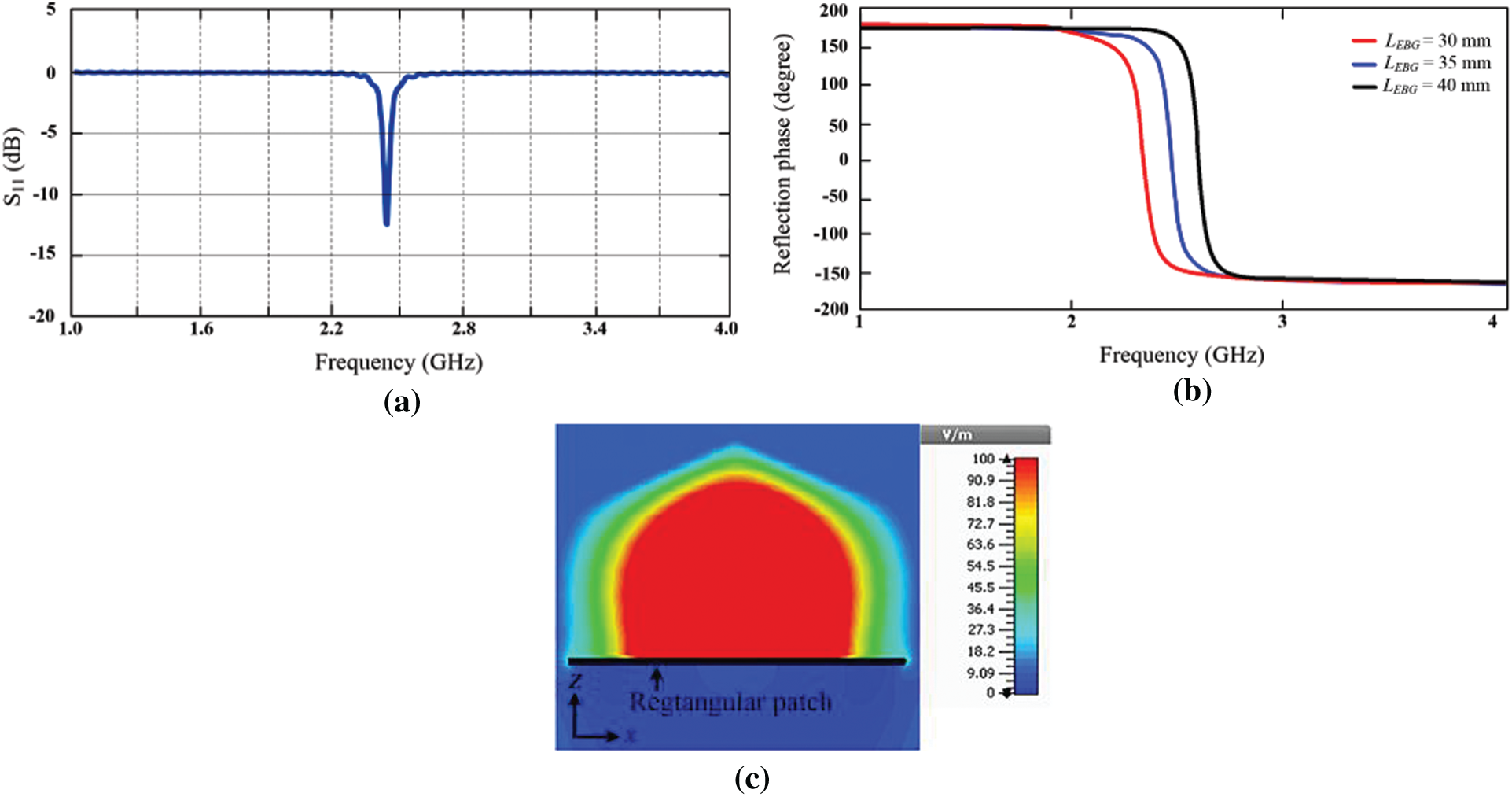
Figure 7: Simulation results of prototype antenna upon addition of eight mushroom-like EBG patches. (a) Reflection coefficient, (b) reflection phase, (c) electromagnetic near-field distribution over prototype antenna
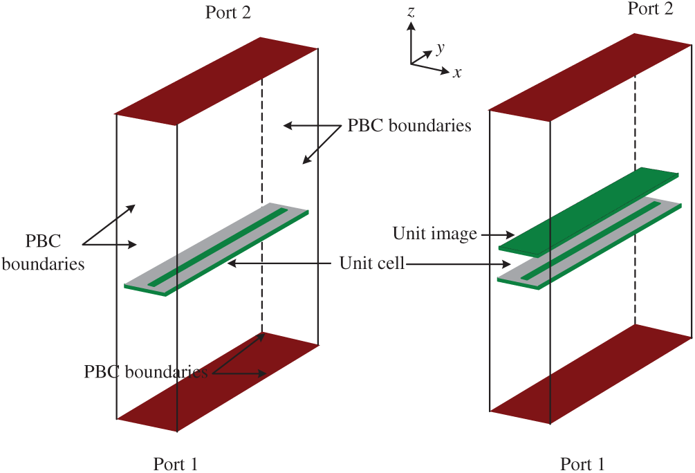
Figure 8: Unit-cell model for slot-shaped metamaterial
The simulation model of a single unit cell for the slot-shaped metamaterial is shown in Fig. 8. The permeability and permittivity both had a positive value approaching zero, MENZ, with the characteristic that allows waves to propagate; thus, as shown in Fig. 9, this medium acted as a surface that partially reflected the waves and partially transmitted the waves. This type of material provides a 2D electromagnetic frequency gap.
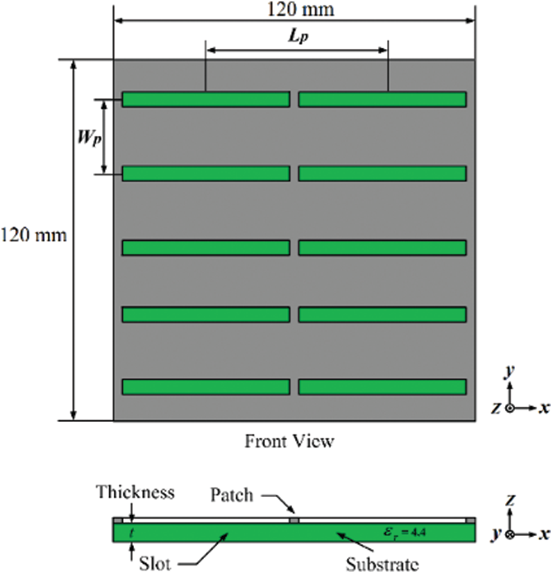
Figure 9: Multiple-cell model for slot-shaped metamaterial
From the design and simulation of the sub-structure sheet structure, as shown in Fig. 2a, the radiator matrix (
The simulation results for the permittivity (
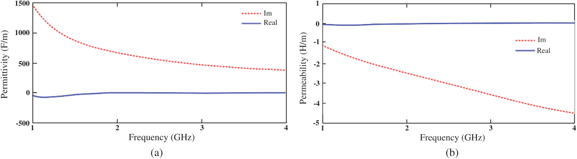
Figure 10: Simulated results of slot-shaped unit. (a) Permittivity (
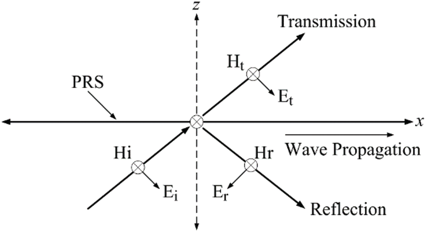
Figure 11: Electromagnetic propagation when passing through a medium
A. TE polarization mode
Fig. 12a depicts the TE polarization mode. The metamaterial setup based on a slot is depicted along the y axis, so the electromagnetic waves propagate in the x direction. The electric fields of the rectangular microstrip antenna propagate along the y axis. Therefore, the TE polarization mode can have more magnetic fields of transmitted waves than reflected waves, as shown in Fig. 13a.
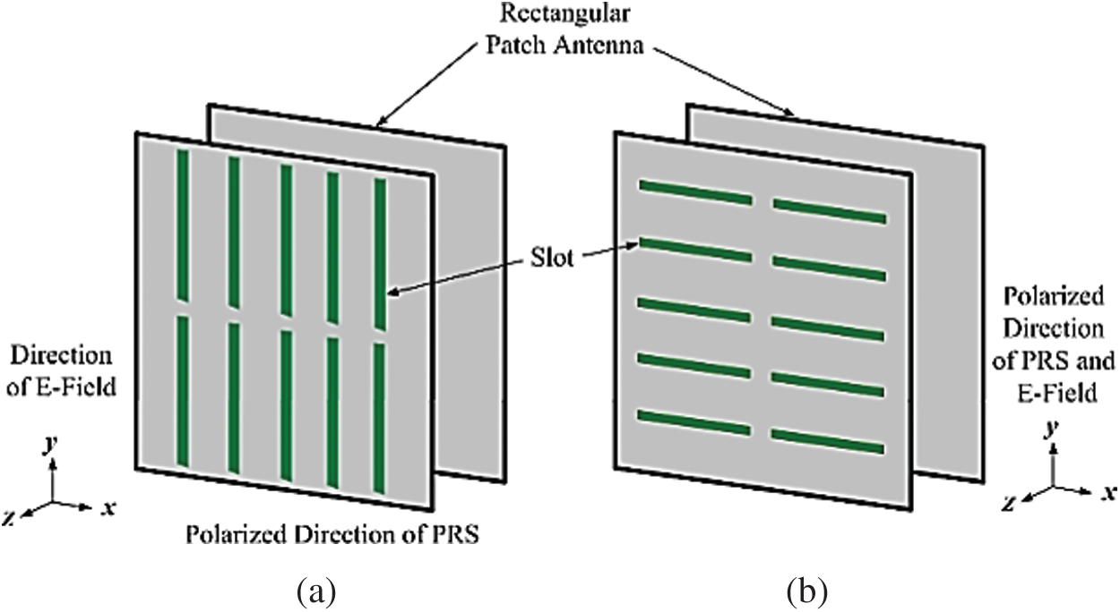
Figure 12: Geometries of resonator antenna. (a) TE, (b) TM
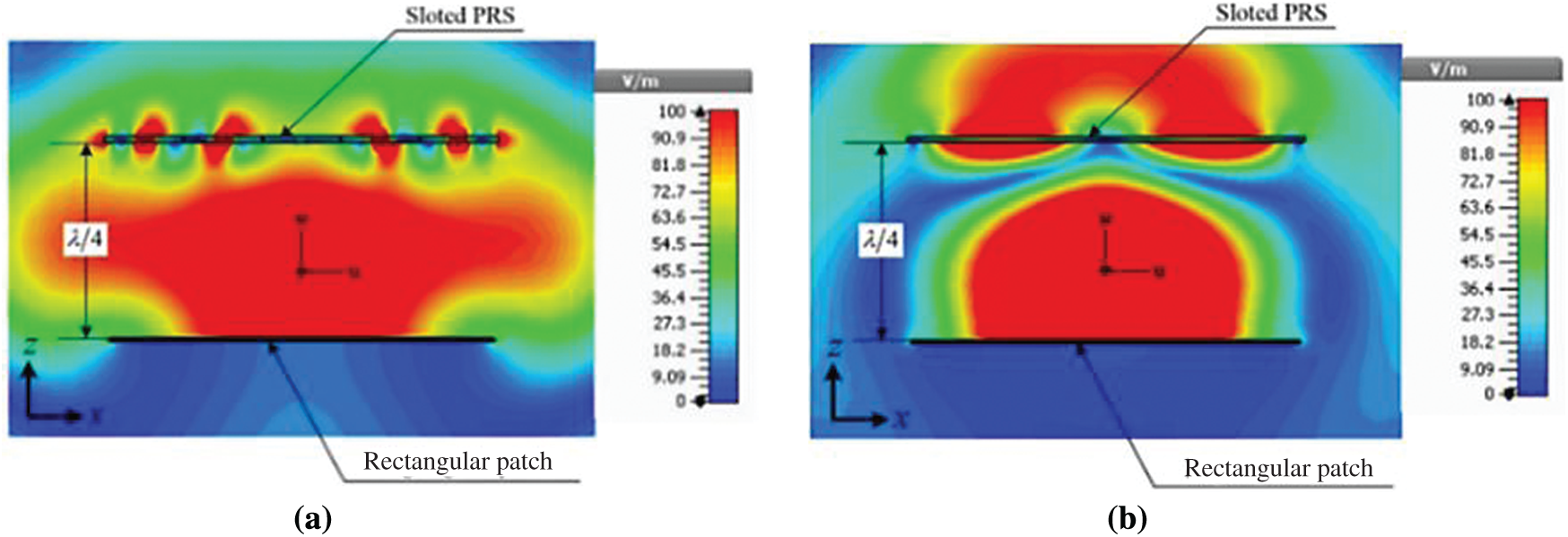
Figure 13: Electric field intensity propagation passing through the medium near-field distributions of proposed TE and TM modes. (a) TE mode, (b) TM mode
B. TM polarization mode
The metamaterial setup based on the slot-shaped structure is along the x axis, so the electromagnetic waves propagate in the y direction. Furthermore, the electric fields of a primary radiator propagate along the y axis. Consequently, the PRS polarization direction has only electric fields in the TM polarization mode, as displayed in Fig. 12b. In this case, the propagation of the transmitted waves can be less than that of the reflected waves, as shown in Fig. 13b.
From the theory explained above, the wave propagation is obstructed by the metamaterials based on the PRS slot-shaped structure along the x and y directions in the TE and TM polarization modes, respectively.
In TE mode, the slot-shaped metamaterials act as the rectangular microstrip superstrate installed on an antenna with a quarter-wavelength dimension in the medium for radiating in phase. Fig. 13a illustrates the near-field distribution of the proposed TE mode. It can be seen that the spread of waves radiating through a slot-shaped superstrate is small. The red area shows the maximum electric field strength from the rectangular patch antenna that could reach only marginally to the top of the metamaterial plate surface due to the impedance mismatch between the antenna and metal plate mounted along the cross-section. The yellow, green, blue, and dark blue areas show the decreasing electric field intensity.
However, as shown in Fig. 13b, the wave propagation of the TM mode can be seen to be radiating very well. It was found that the maximum electric field strength could be exported from the antenna through the top of the metal sheet in the same direction due to the excellent impedance between the antenna and metal plate in the same horizontal direction. c, f,
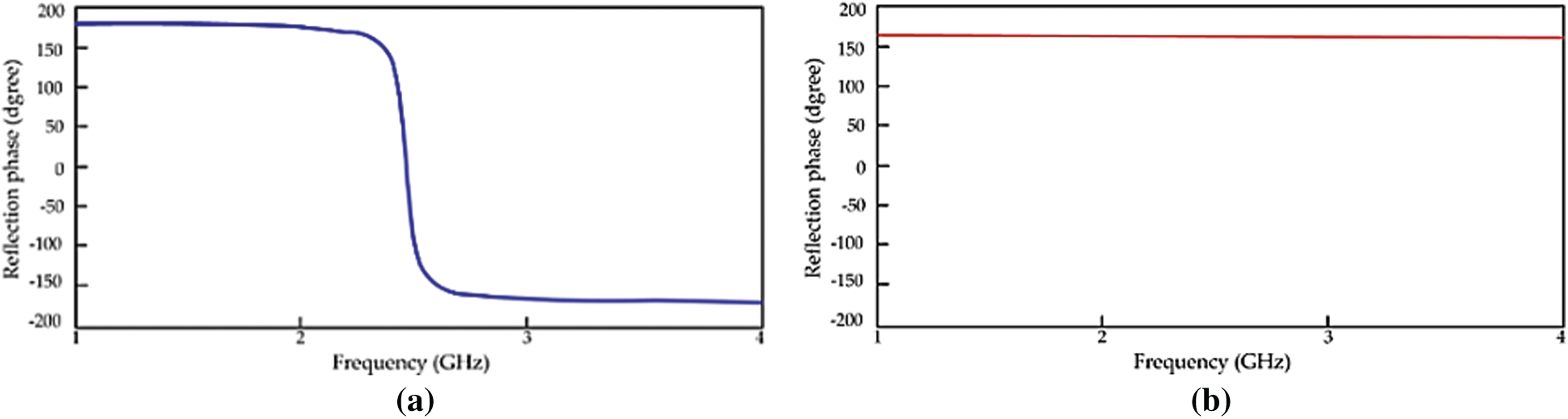
Figure 14: Simulation results of reflection phases of metamaterials. (a) Reflection phase of EBG at 2.45 GHz, (b) reflection phase of PRS at 2.45 GHz
Simulation results of the proposed microstrip antenna gain with the EBG and metamaterial sheet are shown upon changing the distance between
Table 1: Simulation gain results of proposed antenna

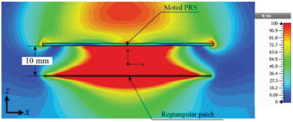
Figure 15: Near-field distributions
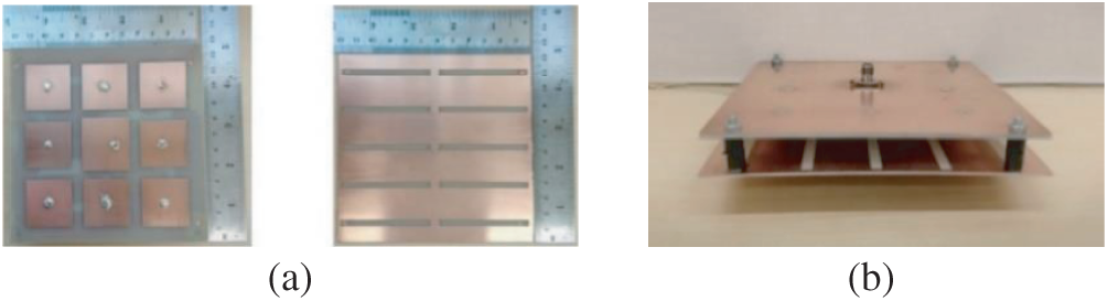
Figure 16: Photographs of proposed antenna. (a) Rectangular microstrip antenna with EBG surface and PRS (b) resonator antenna
Table 2: Parameters of proposed antenna
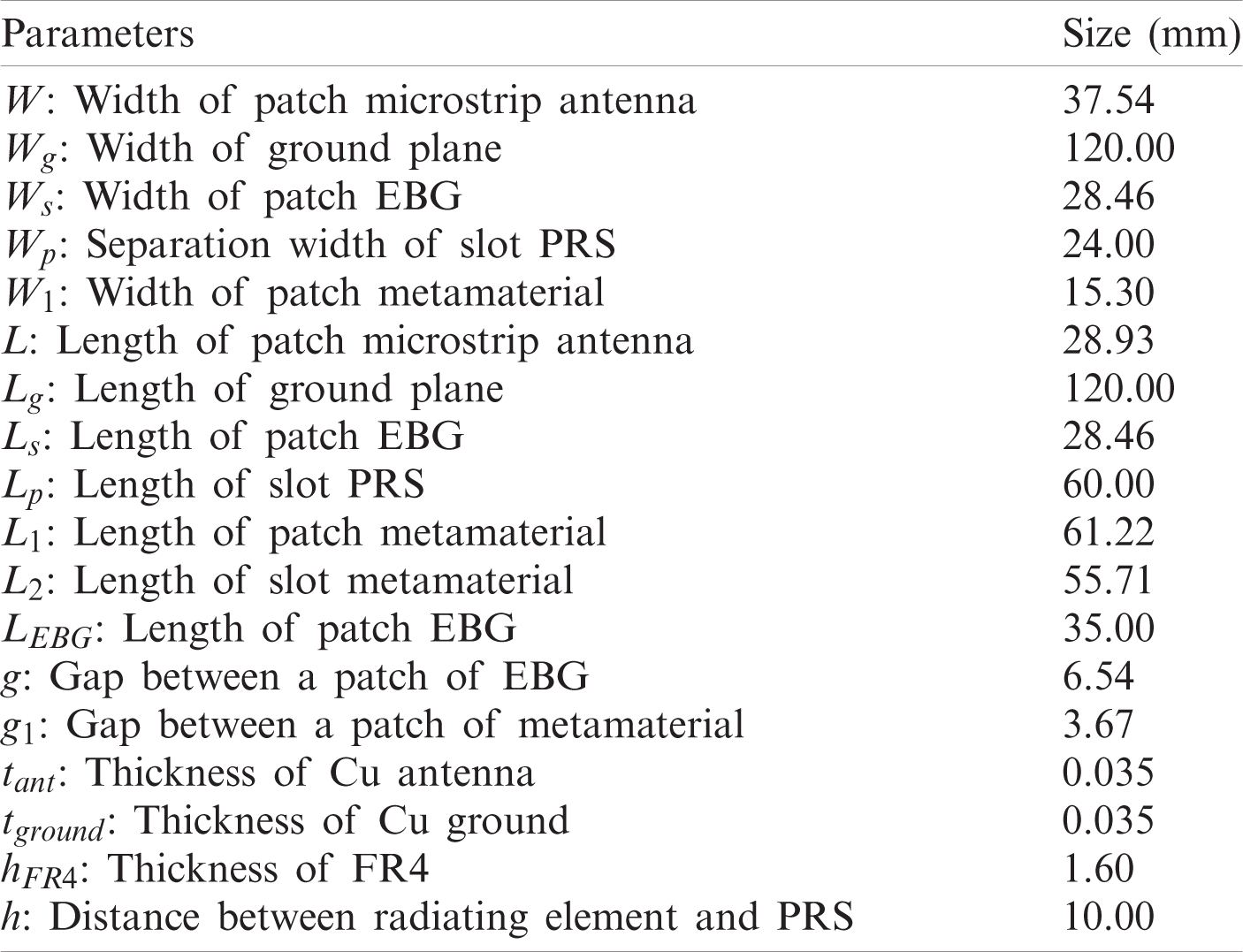
The rectangular microstrip antenna prototype is surrounded by a mushroom-liked EBG, which was fabricated using two sides of FR4 sheet with a dielectric constant of 4.3, as shown in Fig. 16a. In addition, the PRS superstrate was located above the radiating element with a spacing of approximately 10 mm, as shown in Fig. 16b. When S11 is analyzed as shown in Fig. 17, Tab. 3 illustrates the simulated and measured results for the proposed antenna. The input impedances of simulation and measurement results were close to 50
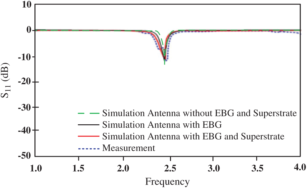
Figure 17: Simulated and measured S11 (dB)
Table 3: Simulated and measured results for antenna based on S11 and voltage standing wave ratio (VSWR)

A microstrip antenna was reconstructed from a conventional patch using an EBG surface placed on a similar rectangular patch to improve directional gain from 7.21 to 8.08 dB. Subsequently, when the directional antenna was applied to the resonator antenna by adding the PRS superstrate, the maximum gain increased to 11.97 dB. When the proposed antenna was compared with the patch microstrip antenna, the directional gain efficiency was enhanced to 39.76%. The 3D perspective of the radiation pattern with maximum gain is shown in Fig. 18.
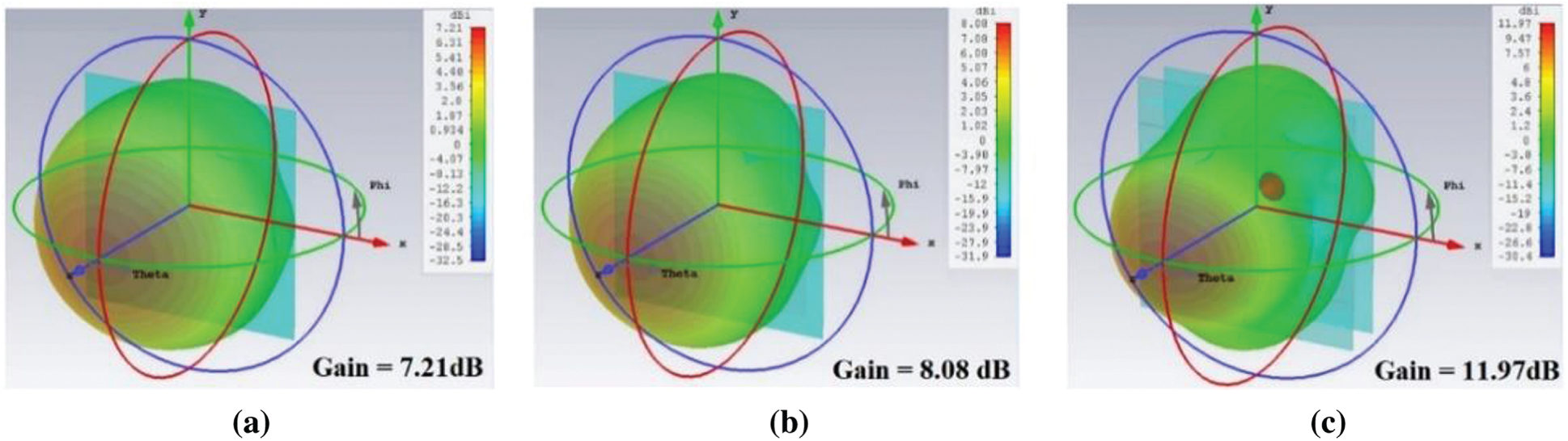
Figure 18: 3D perspectives of radiation pattern with maximum gain: (a) Patch microstrip antenna, (b) patch microstrip antenna surrounded with EBG, and (c) proposed antenna
The results of comparing the measured and simulated gains of the microstrip antenna in Fig. 16 are shown in Tab. 4. These results tend to be in the same direction with the maximum gain of 11.97 dB. The efficiency was increased by 39.76%.
Table 4: Comparison of measured and simulated gains of various antenna types

The radiation pattern in the E- and H-planes at a frequency of 2.45 GHz are plotted in Fig. 19. The characteristic of the radiated energy patterns is that of a directional radiation pattern. However, a back lobe perhaps appeared because the resonator antenna reflected and forwarded high-power waves. The half-power beamwidth in the E- and H-planes were 54.6
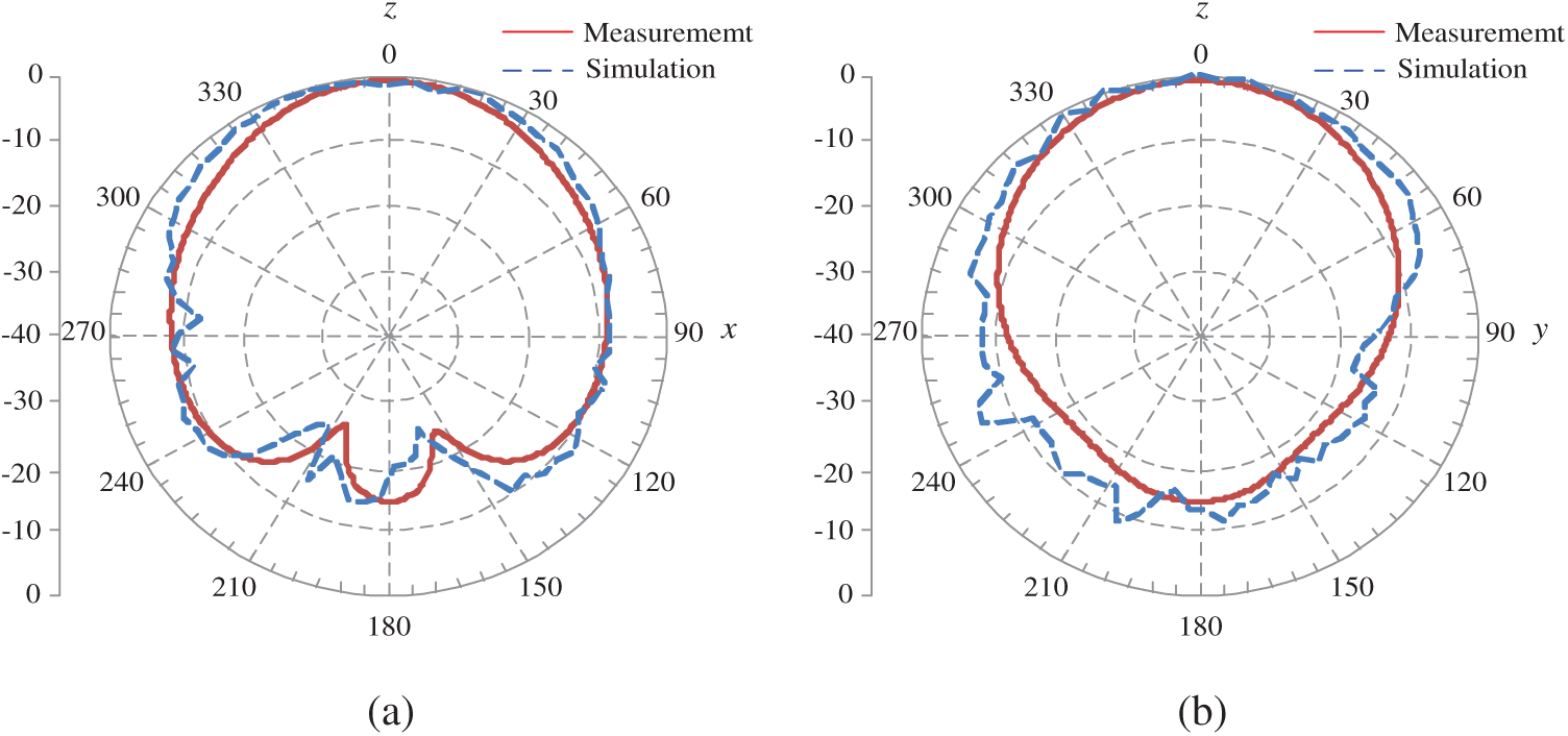
Figure 19: Simulated and measured radiation patterns. (a) E-plane, (b) H-plane
The DC energy-harvesting measurement from connecting the prototype antenna with the rectifier and voltage multiplier circuits is shown as a block diagram in Fig. 20. The experiment was done with voltage multiplier circuits of 6, 8, 10, and 12 times, tested at 0.6 m, which was the best distance for receiving maximum voltage. It was found from the experimental results that a multiplier circuit of 8 times yielded better performance than that of 6, 10, or 12 times, as shown in Tab. 5.
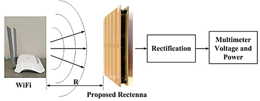
Figure 20: Block diagram of ambient RF energy harvesting
Table 5: Energy-harvesting measurement results

4 Rectenna System Measurement Results
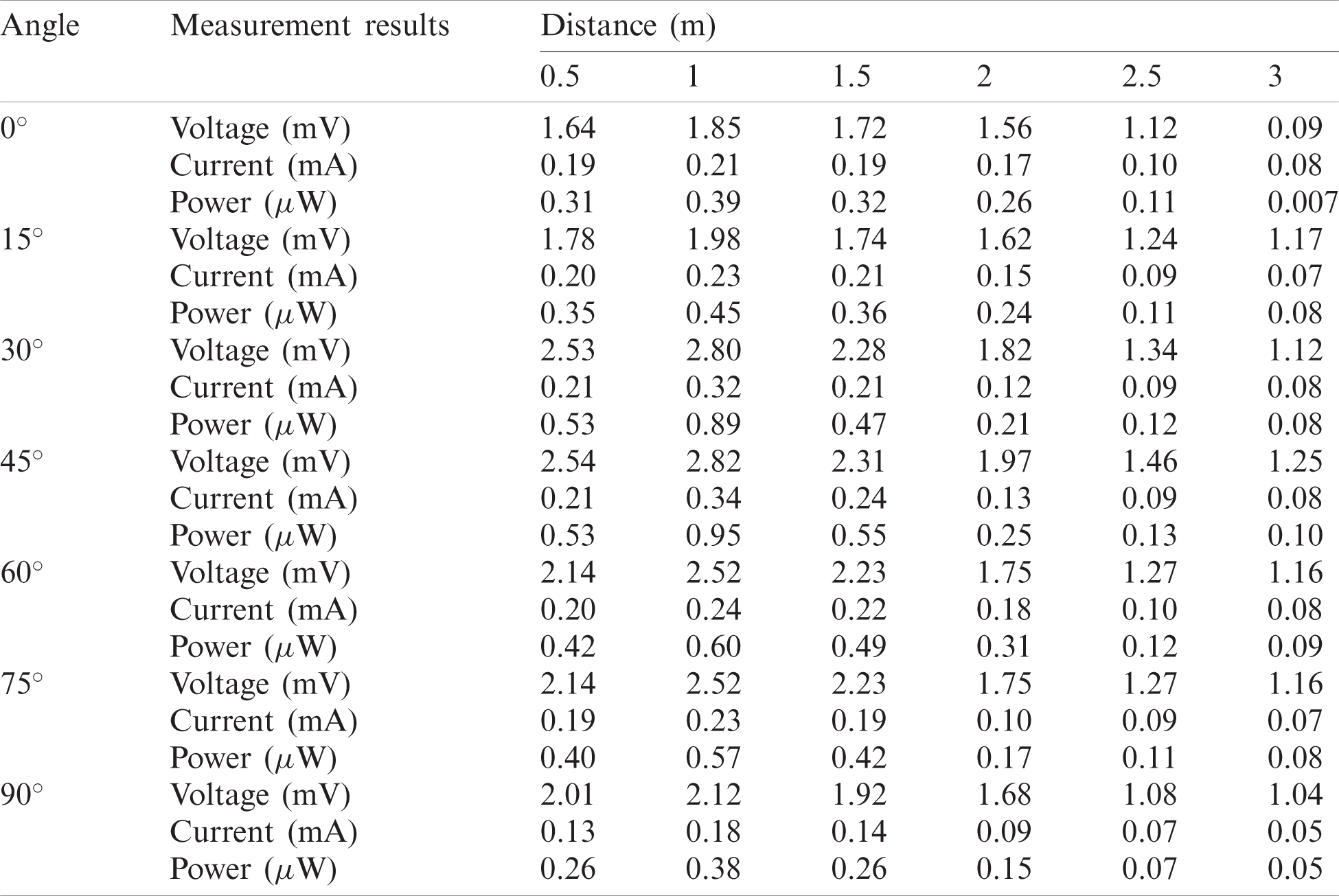
Experiments were carried out on two parameters for receiving maximum energy: signal receiving distance and direction angle of the Wi-Fi spot and rectenna response. The signal receiving distances were 0.5, 1, 1.5, 2, 2.5, and 3 m, and the direction angles of the Wi-Fi spit and rectenna response were 0
Table 6: Energy harvesting measurement results
The design and construction of a rectenna system using a directional microstrip antenna with an integrated magnetic stripe design (EBG) plate with a multiple voltage circuit were presented. The antenna designed in the present work was compared with those designed in previous works as follows.
In [29], an uncomplicated antenna with a gain of 8.6 dBi for low-energy harvesting at the 2.45 GHz frequency band was designed. The rectenna in [30] consisted of an antenna with a directional gain of 6.7 dB at 2.45 GHz. A rectifier circuit with a HSMS2850 diode achieved low-energy harvesting with an efficiency of 63% when the input power was 0 dBm. The designed antenna matched the rectifying circuit and eliminated unwanted harmonics, resulting in an 83% efficiency when using a 1400-
A rectifier circuit with four switch diodes and an interdigital capacitor was designed to increase the DC output voltage in another antenna [31] that operated at the 2.45-GHz frequency band to reduce high harmonic values and had a gain of 7.13 dB, resulting in an efficiency of 78.7% when using 4 k
Another antenna was designed using square-shaped tuning techniques to tune the impedance bandwidth and increase the maximum gain to 5.6 dB [32]. This antenna is compact, measuring
In [33], frequency-selective-surface (FSS) sheet structure techniques were used for RF energy harvesting with a geometric shape consisting of a sequence of unit cells. The gain was 9.4 dB when connected with a full-wave rectifier circuit that could convert power up to a conversion rate of 61% at a transmitted power of 15 dBm. The gain and transmitted power are both high, but the structure is complicated.
In [34], a square
The authors of [35] introduced a monopolar antenna using triangular grooving techniques on the ground plane and an I-shaped reflector in implementing the air-gap technique. A gain of 8.36 dB was obtained. Combined with a full-wave rectifier circuit, this antenna could convert power at a conversion rate of up to 40% at 0 dBm at a maximum voltage of 0.46 V and convert voltage up to 6 V when using signal power up to 30 dBm. The antenna structure is not complicated, but has low gain.
In the method proposed in the present paper, a low signal power on the input power of −30.04 dB was used, transmitted at a distance of 1 m with a higher efficiency of 95.88%, as shown in Tab. 7.
Table 7: Comparison of rectenna efficiencies

The method for designing the structure and energy-harvesting circuit for an antenna proposed this research increased the antenna gain, reduced the complexity of the antenna structure, and obtained efficiency with a multiple voltage circuit. The antenna structure is a rectangular directional microstrip that is combined with an EBG mushroom-shaped magnetic frequency gap that can control the radiation direction and a
Acknowledgement: The authors thank the Department of Telecommunications Engineering, Faculty of Engineering and Architecture, Rajamangala University of Technology Isan, Thailand, for equipment support and research funding. Moreover, they gratefully acknowledge the use of computer simulation software for supporting this research work sponsored by the School of Telecommunication Engineering, Suranaree University of Technology, Nakhon Ratchasima, Thailand.
Funding Statement: This work is supported by the Rajamangala University of Technology Thanyaburi research and development fund.
Conflicts of Interest: The authors declare that they have no conflicts of interest to report regarding the present study.
1. M. H. Nehrir, C. Wang, K. Strunz, H. Aki, R. Ramakumar et al., “A review of hybrid renewable/alternative energy systems for electric power generation: Configurations, control, and applications,” IEEE Transactions on Sustainable Energy, vol. 2, no. 4, pp. 392–403, 2011. [Google Scholar]
2. T. H. Oh, S. Y. Pang and S. C. Chua, “Energy policy and alternative energy in Malaysia: Issues and challenges for sustainable growth,” Renewable and Sustainable Energy Reviews, vol. 14, no. 4, pp. 1241–1252, 2010. [Google Scholar]
3. P. McKendry, “Energy production from biomass (part 1Overview of biomass,” Bioresource Technology, vol. 83, no. 1, pp. 37–46, 2002. [Google Scholar]
4. M. S. Dresselhaus and I. L. Thomas, “Alternative energy technologies,” Nature, vol. 414, no. 6861, pp. 332–337, 2001. [Google Scholar]
5. V. Devabhaktuni, M. Alam, S. S. S. R. Depuru, R. C. Green II, D. Nims et al., “Solar energy: Trends and enabling technologies,” Renewable and Sustainable Energy Reviews, vol. 19, no. 8, pp. 555–564, 2013. [Google Scholar]
6. X. Lu, P. Wang, D. Niyato, D. I. Kim and Z. Han, “Wireless networks with RF energy harvesting: A contemporary survey,” IEEE Communications Surveys & Tutorials, vol. 17, no. 2, pp. 757–789, 2014. [Google Scholar]
7. M. Piñuela, P. D. Mitcheson and S. Lucyszyn, “Ambient RF energy harvesting in urban and semi-urban environments,” IEEE Transactions on Microwave Theory and Techniques, vol. 61, no. 7, pp. 2715–2726, 2013. [Google Scholar]
8. F. Iwanda, Z. Zulfi and Y. Wahyu, “Rectifying antenna (rectenna) untuk sinyal tv uhf 470–806 Mhz,” eProceedings of Engineering, vol. 5, no. 3, pp. 5483–5490, 2018. [Google Scholar]
9. R. K. Sidhu, J. S. Ubhi and A. Aggarwal, “A survey study of different RF energy sources for RF energy harvesting,” in Int. Conf. on Automation, Computational and Technology Management, Amity University, London, United Kingdom, pp. 530–533, 2019. [Google Scholar]
10. M. Hasan, M. Rahman, M. R. I. Faruque, M. T. Islam and M. U. Khandaker, “Electrically compact SRR-loaded metamaterial inspired quad band antenna for bluetooth/WiFi/WLAN/WiMAX system,” Electronics, vol. 8, no. 7, pp. 790, 2019. [Google Scholar]
11. C. A. Balanis, “Antenna theory and design,” NY, USA: John Willey & Sons, 1997. [Google Scholar]
12. W. Naktong, P. Boonmaitree, S. Kornsing, E. Khoomwong and A. Ruengwaree, “CPW-fed rectangular aperture antenna with two-step ground-plane tuning for UWB applications,” RMUTI Journal Science and Technology, vol. 7, no. 2, pp. 50–66, 2014. [Google Scholar]
13. W. Naktong, N. Fhafhiem, A. Innok and A. Ruengwaree, “Study of rectanna using directive antenna at frequency of 2.45 GHz,” in 10th South East Asian Technical University Consortium Symp., Tokyo, Japan, 2016. [Google Scholar]
14. E. K. I. Hamad and A. Abdelaziz, “Metamaterial superstrate microstrip patch antenna for 5G wireless communication based on the theory of characteristic modes,” Journal of Electrical Engineering, vol. 70, no. 3, pp. 187–197, 2019. [Google Scholar]
15. A. Lalbakhsh, M. U. Afzal, K. P. Esselle, S. L. Smith and B. A. Zeb, “Single-dielectric wideband partially reflecting surface with variable reflection components for realization of a compact high-gain resonant cavity antenna,” IEEE Transactions on Antennas and Propagation, vol. 67, no. 3, pp. 1916–1921, 2019. [Google Scholar]
16. B. A. Munk, “Frequency selective surfaces: Theory and design,” NY, USA: John Wiley & Sons, 2005. [Google Scholar]
17. S. Luo, Y. Li, Y. Xia and L. Zhang, “A low mutual coupling antenna array with gain enhancement using metamaterial loading and neutralization line structure,” Applied Computational Electromagnetics Society Journal, vol. 34, no. 3, pp. 411–419, 2019. [Google Scholar]
18. H. Ö. Yılmaz and F. Yaman, “Meta-material antenna designs for a 5.8 GHz doppler radar,” IEEE Transactions on Instrumentation and Measurement, vol. 69, no. 4, pp. 1775–1782, 2019. [Google Scholar]
19. M. E. Atrash, M. A. Abdalla and H. M. Elhennawy, “A wearable dual-band low profile high gain low SAR antenna AMC-backed for WBAN applications,” IEEE Transactions on Antennas and Propagation, vol. 67, no. 10, pp. 6378–6388, 2019. [Google Scholar]
20. P. K. T. Rajanna, K. Rudramuni and K. Kandasamy, “A high-gain circularly polarized antenna using zero-index metamaterial,” IEEE Antennas and Wireless Propagation Letters, vol. 18, no. 6, pp. 1129–1133, 2019. [Google Scholar]
21. B. Hasan and K. Raza, “Dual band slotted printed circular patch antenna with superstrate and EBG structure for 5G applications,” Mehran University Research Journal of Engineering and Technology, vol. 38, no. 1, pp. 227–238, 2019. [Google Scholar]
22. W. Brown, J. Mims and N. Heenan, “An experimental microwave-powered helicopter,” in 1958 IRE Int. Convention Record, New York, NY, USA, pp. 225–235, 1966. [Google Scholar]
23. Q. Chen and H. Zhang, “High-gain circularly polarized fabry-pérot patch array antenna with wideband low-radar-cross-section property,” IEEE Access, vol. 7, pp. 8885–8889, 2019. [Google Scholar]
24. X. Jiang, F. Jia, Y. Cao, P. Huang, J. Yu et al., “Ka-band
25. J. Khan, D. A. Sehrai, M. A. Khan, H. A. Khan, S. Ahmad et al., “Design and performance comparison of rotated y-shaped antenna using different metamaterial surfaces for 5G mobile devices,” Computers, Materials & Continua, vol. 60, no. 2, pp. 409–420, 2019. [Google Scholar]
26. D. A. Sehrai, F. Muhammad, S. H. Kiani, Z. H. Abbas, M. Tufail et al., “Gain-enhanced metamaterial based antenna for 5G communication standards,” Computers, Materials & Continua, vol. 64, no. 3, pp. 1587–1599, 2020. [Google Scholar]
27. S. H. Kiani, A. Altaf, M. Abdullah, F. Muhammad, N. Shoaib et al., “Eight element side edged framed MIMO antenna array for future 5G smartphones,” Micromachines, vol. 11, no. 11, pp. 1–13, 2020. [Google Scholar]
28. E. A. Kadir, A. P. Hu, M. Biglari-Abhari and K. C. Aw, “Indoor WiFi energy harvester with multiple antenna for low-power wireless applications,” in 2014 IEEE 23rd Int. Symp. on Industrial Electronics, Istanbul, Turkey, pp. 526–530, 2014. [Google Scholar]
29. H. Sun, Y. X. Guo, M. He and Z. Zhong, “Design of a high-efficiency 2.45-GHz rectenna for low-input-power energy harvesting,” IEEE Antennas and Wireless Propagation Letters, vol. 11, pp. 929–932, 2012. [Google Scholar]
30. Y. Huang, N. Shinohara and H. Toromura, “A wideband rectenna for 2.4 GHz-band RF energy harvesting,” in IEEE Wireless Power Transfer, Aveiro, Portugal, pp. 1–3, 2016. [Google Scholar]
31. S. Ahmed, Z. Zakaria, M. N. Husain and A. Alhegazi, “Design of rectifying circuit and harmonic suppression antenna for RF energy harvesting,” Journal of Telecommunication, Electronic and Computer Engineering, vol. 9, no. 2–13, pp. 63–67, 2017. [Google Scholar]
32. Q. Awais, Y. Jin, H. T. Chattha, M. Jamil, H. Qiang et al., “A compact rectenna system with high conversion efficiency for wireless energy harvesting,” Journal of Telecommunication, Electronic and Computer Engineering, vol. 9, no. 2–13, pp. 63–67, 2017. [Google Scholar]
33. F. Erkmen, T. S. Almoneef and O. M. Ramahi, “Scalable electromagnetic energy harvesting using frequency-selective surfaces,” IEEE Transactions on Microwave Theory and Techniques, vol. 6, no. 5, pp. 2433–2441, 2018. [Google Scholar]
34. X. Li, L. Yang and L. Huang, “Novel design of 2.45-GHz rectenna element and array for wireless power transmission,” IEEE Access, vol. 7, pp. 28356–28362, 2019. [Google Scholar]
35. M. A. M. Said, Z. Zakaria, M. N. Husain, M. H. Misran and F. S. M. Noor, “2.45 GHz rectenna with high gain for RF energy harvesting,” Telkomnika, vol. 17, no. 1, pp. 384–391, 2019. [Google Scholar]
36. S. Ahmed, M. N. Husain, Z. Zakaria, M. S. I. M. Zin and A. Alhegazi, “Rectenna designs for RF energy harvesting system: A review,” International Journal on Communications Antenna and Propagation, vol. 6, no. 2, pp. 82–91, 2016. [Google Scholar]
37. W. Hong, Y. Cao, L. Deng, S. Li, M. Li et al., “A circular polarized rectenna with out-of-band suppression for microwave power transmission,” International Journal of Antennas and Propagation, vol. 2016, pp. 1–7, 2016. [Google Scholar]
38. N. Fhafhiem, P. Krachodnok and R. Wongsan, “Curved strip dipole antenna on EBG reflector plane for RFID applications,” Wseas Transactions on Communications, vol. 9, pp. 374–383, 2010. [Google Scholar]
 | This work is licensed under a Creative Commons Attribution 4.0 International License, which permits unrestricted use, distribution, and reproduction in any medium, provided the original work is properly cited. |