DOI:10.32604/cmc.2021.016922
| Computers, Materials & Continua DOI:10.32604/cmc.2021.016922 | |
| Article |
System Performance of Wireless Sensor Network Using LoRa–Zigbee Hybrid Communication
1Faculty of Electrical and Electronic Engineering, Duy Tan University, Da Nang, 550000, Vietnam; Institute of Research and Development, Duy Tan University, Da Nang, 550000, Vietnam
2Graduate School, Duy Tan University, Da Nang 550000, Vietnam; Faculty of Information Technology, Duy Tan University, Da Nang, Vietnam
3Department of Basic Science, College of Science and Theoretical Studies, Saudi Electronic University, Jeddah Campus, KSA
*Corresponding Author: Anand Nayyar. Email: anandnayyar@duytan.edu.vn
Received: 15 January 2021; Accepted: 17 February 2021
Abstract: Wireless sensor network (WSN) is considered as the fastest growing technology pattern in recent years because of its applicability in varied domains. Many sensor nodes with different sensing functionalities are deployed in the monitoring area to collect suitable data and transmit it to the gateway. Ensuring communications in heterogeneous WSNs, is a critical issue that needs to be studied. In this research paper, we study the system performance of a heterogeneous WSN using LoRa–Zigbee hybrid communication. Specifically, two Zigbee sensor clusters and two LoRa sensor clusters are used and combined with two Zigbee-to-LoRa converters to communicate in a network managed by a LoRa gateway. The overall system integrates many different sensors in terms of types, communication protocols, and accuracy, which can be used in many applications in realistic environments such as on land, under water, or in the air. In addition to this, a synchronous management software on ThingSpeak Web server and Blynk app is designed. In the proposed system, the token ring protocol in Zigbee network and polling mechanism in LoRa network is used. The system can operate with a packet loss rate of less than 0.5% when the communication range of the Zigbee network is 630 m, and the communication range of the LoRa network is 3.7 km. On the basis of the digital results collected on the management software, this study proves tremendous improvements in the system performance.
Keywords: Wireless sensor network; Zigbee; LoRa; communication protocol; converter; packet loss
In recent years, wireless sensor networks (WSNs) are attracting much attention from academia as well as industry. WSN has been widely applied in many industries and fields, such as environmental monitoring [1], industrial Internet of Things (IoT), contact tracing [2], health monitoring, and intelligent transport [3,4]. These systems require a large number of sensors to be distributed in an area to collect environmental parameters and communicate with the sink node or the central station via wireless link.
Numerous studies often hypothesize that all sensor nodes in WSNs are homogeneous [5,6], but such networks do not actually exist. Even industrial-designed homogeneous sensors have many different capacities in terms of initial energy level and energy degradation rate [7,8]. Furthermore, large WSNs often deploy several different types of sensors and protocols to work together, forming heterogeneous WSNs [9,10]. Hence, the assurance of Quality of Service (QoS) and resource optimization in heterogeneous WSNs brings a number of challenges [11].
Solutions focus on designing hardware and software systems in WSNs synchronously by using techniques such as clustering, radio optimization, data reduction, sleep or wake-up methods, energy efficient routing protocols, and energy harvesting [12]. Many communication protocols for WSNs are developed, such as Bluetooth, Wi-Fi, BLE, Zigbee, LoRa, NB-IoT, and LTE-M [13]. In particular, with their outstanding technical advantages, Zigbee and LoRa are currently being used more commonly in WSNs.
ZigBee technology is high-level communication built based on 802.15.4 standard using low-power radio signals with a shortwave frequency of Institute of Electrical and Electronics Engineers (IEEE) [14–17]. Zigbee provides star, tree, and mesh topologies. WSN often uses mesh topology because it allows for continuous communication and can redefine the network configuration when packet transmits from one node to other. Each node in the mesh can connect and route traffic with neighboring nodes [18].
A ZigBee network consists of up to three types of devices [14], as follows:
✓Zigbee Coordinator (ZC): It is the original device capable of deciding the network structure, defining the addressing method, and keeping the address stable. Every network has only one coordinator. It is also the only component that can communicate with other networks.
✓Zigbee Router (ZR): It has the functions of intermediate routing to transmit data; detect and map surrounding nodes; and monitor, control, and collect data like a normal node. Routers usually work on active mode to communicate with other parts of the network.
✓Zigbee End Device (ZED): The nodes in ZED only communicate with the ZC coordinator or ZR near it. They are considered the endpoint of the network and are only responsible for operating/reading information from the physical components. ZED has a simple construction and is usually in sleep mode to save energy. The nodes are only “awakened” when they need to receive or send a particular message.
Short for “long range,” LoRa is the new IoT communication technology that runs on top of the LoRaWAN network protocol. LoRa technique is based on chirp spread spectrum technology, which can connect to sensors more than 15–30 miles away in rural areas [19–21]. The LoRa data are hashed with high-frequency pulses to produce a signal with a frequency range higher than that of the original data (i.e., chipped). The high-frequency signal is then encoded in chirp signal chains, which are sinusoidal signals whose frequency changes over time. The two types of chirp signals are up-chirp and down-chirp. The frequency of up-chirp increases with time, whereas that of down-chirp decreases with time. According to the principle of encoding, bit 1 uses up-chirp, and bit 0 uses down-chirp before transmitting to the antenna for sending. This principle helps reduce the complexity and accuracy of the receiver circuit and outperform traditional modulation schemes, such as frequency shift keying [20,22]. Moreover, LoRa has many advantages such as frequency-free operation and easy installment. It can also be deployed on a large scale owing to its simple architecture and integrated with two security layers: one at the network layer and the other at the application layer with AES encryption. Using the LoRa technique can solve the problem of coverage expansion of WSNs [23,24].
In this study, we investigate a heterogeneous WSN based on Zigbee and LoRa communication, in which the sensors are classified to the cluster network. We also use the LoRa-Wi-Fi gateway to transfer data to the server. Our system ensures compatibility with existing Zigbee systems and integrates LoRa to solve coverage expansion in heterogeneous WSN at no extra cost.
The main contribution of the work are as follows:
✓Heterogeneous WSN based on Zigbee and LoRa communication is proposed, which contains four clusters: two Zigbee clusters, one underwater LoRa cluster, and one agricultural LoRa cluster. The system can connect to a variety of sensors such as temperature/humidity, light intensity, GAS, turbidity, and pH sensors that are very flexible in installation.
✓Token ring protocol in Zigbee network and polling mechanism in LoRa for heterogeneous WSN is proposed to decrease the packet loss rate to < 0.5%.
✓Software system being proposed for monitoring parameters on web and smartphone.
This paper is organized as follows. Section 2 highlights literature review. Section 3, entails the description regarding hardware and software used for proposed system. Section 4 gives detailed description regarding system performance. Section 5 concludes the paper with future scope.
In this section, we present studies related to Zigbee and LoRa communication.
Abraham et al. [9] proposed air quality monitoring models based on WSNs using Zigbee. In particular, the hardware model is deployed indoor with six measurement nodes that simultaneously communicate with one another using Zigbee network based on Arduino and XBee transmission modules. The parameters are collected, sent to the base station and stored at the server, and presented in visual graphs. However, the work does not focus on system protocol, and it is designed in the form of a circuit board made up of pairing discrete modules, which are not according to industry standards. It also leads to a problem when adjusting the sensor and is challenging to apply in practice.
The same problem was encountered by Ma et al. [10]. Specifically, they applied WSN in agriculture to save water consumption. The sensor nodes collect energy and transmit to the central data processing station via Zigbee. The central station makes the appropriate irrigation decisions and ensure water saving as much as possible. However, the system uses AC–DC adapter power to operate under AC power conditions, which is not feasible in practice.
Ulusar et al. [11] proposed examining the system performance of Zigbee D2D in terms of received signal strength indicator (RSSI) and time of flight (ToF). The system consists of one transmit node and one receiver node that communicate with each other via handshake protocol. The local node sends a command to the remote node and requires the sensing data. When the local node receives the requested information, it computes the ToF and returns an ACK message to indicate that the communication is finished. The proposed system model is simple and, hence, does not highlight the advantages of Zigbee Mesh network.
Bianchi et al. [13] proposed RSSI-based indoor localization and identification for ZigBee WSN in smart homes. The system is designed in the form of a wearable module, including an 89C51 microcontroller that communicates with the CC2531 SoC module. The system operates under a 3V PIN source and can communicate with five different types of sensors, which are pressure sensor, passive infrared sensor, temperature or humidity sensor, distance sensor, and magnetic contactor. This work focuses on hardware design, but software optimization is also essential.
Liu et al. [15] proposed LoRa-based WSNs applied to agriculture. The work describes how to design network nodes that employ many sensor modules and show the result in server websites. However, the system uses only solar power, which limits the system’s uptime when it is dark or there is not enough light. Furthermore, non-industry standard boards can be energy consuming and challenging to calibrate.
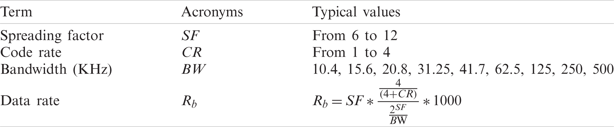
Augustin et al. [20] provided the LoRa network architecture for communication protocols, LoRa, and LoRaWAN frames. The relationship between the main parameters controlling the system at the physical layer, such as bandwidth (BW), spreading factor (SF), and code rate (CR), is also presented. From there, the authors provided a formula for calculating the duration of a symbol (TS) and bit rate (Rb). Finally, they proposed a test model of a LoRa network with many different test scenarios and compared it with an ALOHA network.
González et al. [21] proposed LoRa sensor network for monitoring air quality or detecting gas leakage events. The sensing board developed includes a connector for the LoRa32 development board, sensor BME680 from Bosch GmbH, and a micro-SD card socket. The system can work continuously in industrial environments and achieve high performance.
Through the above literature review, it is observed that many problems still need to be solved to increase the performance of WSNs. A solution that combines wireless communication techniques in the same network is proposed [25,26]. A combined network of Zigbee and LoRa is proposed in the first Global Power, Energy, and Communications Conference 2019 (IEEE GPECOM2019) in Cappadocia, Turkey, which was held in June 2019. Specifically, the combination of these two networks makes use of the available resources of the Zigbee network and expands the coverage of the network using LoRaWAN. Ali et al. [25] proposed a WSN model based on a combination of Zigbee and LoRa. The system uses STM32 as the central processor, with the SX1278 module for LoRa communication and the XBee Pro module for Zigbee communication.
The aforementioned studies show that the interoperability between IoT wireless communication techniques remains quite limited. To our knowledge, there is no complete solution with Zigbee and LoRa for heterogeneous WSN. This is the driving force for us to develop a system that combines these wireless communication technologies in a heterogeneous WSN system.
In this section, a heterogeneous WSN based on Zigbee–LoRa communication is proposed. It is a robust, low-power, and scalable network for multiple functions, i.e., monitoring of environmental parameters on the ground, under water, and in the air. This WSN is physically deployed by four main elements: the Zigbee sensor cluster, the LoRa sensor cluster, the Zigbee-to-LoRa converter, and the gateway. Moreover, the network uses the ThingSpeak and Blynk cloud server for the storing of sensor data and the processing and visualization of the data.
Fig. 1 depicts the proposed system. The system has two Zigbee sensor clusters that consists of a set of Zigbee sensor nodes for air monitoring function. Nodes can communicate with each other via Zigbee-to-LoRa converter in the 2.4 GHz band with fast data transmission in a short distance. There are two types of LoRa sensor cluster, one for underwater monitoring and another for agriculture monitoring. LoRa sensor clusters include LoRa sensor nodes that communicate in 433 MHz bands with slow data rate in very long-distance transmission. The Zigbee-to-LoRa converter is used to convert the Zigbee signal to LoRa and is located near the Zigbee cluster. The indoor LoRa gateway is placed in an accessible Internet location. If a Wi-Fi connection is available, then this gateway will automatically connect to the ThingSpeak and Blynk cloud server to forward the uplink and downlink data sent from the clusters to the server and vice versa. We easily extend the system with 32 Zigbee sensor nodes and 64 LoRa sensor nodes with such a structure.

Figure 1: System model
This section presents the hardware design and technical working of the proposed system. Fig. 2 shows the schematic and PCB of the Zigbee node, which is responsible for monitoring air quality using MQ4 and MQ7 sensors. We use two 18650 batteries for the linear voltage regulation for the circuit, and this architecture is used for all other modules in the system. The Atmega328P microprocessor (MCU) collects sensor data through the ADC AD7705 module via SPI protocol. AD7705 is a 16-bit high-resolution Delta-Sigma ADC unit. It is equipped with a 50/60 Hz noise filter, decimation filtering module, and quantization noise shaping to achieve high-quality antialiasing filtering. Environment parameters are displayed locally on the LCD

Figure 2: Schematic and PCB of Zigbee node
Fig. 3 shows the schematic and PCB of the LoRa node, that is responsible for monitoring the agricultural parameters. MCU uses one-wire protocol to connect with the temperature/humidity sensor DHT11, I2C protocol to connect with the light intensity sensor BH1750, and ADC protocol to connect with the soil humidity sensor. All these parameters are displayed on LCD

Figure 3: Schematic and PCB of LoRa node
Fig. 4 shows the schematic and PCB of the underwater LoRa node, which is responsible for monitoring the turbidity and pH sensor parameters. We use the ADC protocol to connect the MCU with SEN0189 and SEN0161 sensors from DFRobot. The data are displayed locally on the LCD
where v is the voltage received from the optical transistor.

Figure 4: Schematic and PCB of underwater node
When using the pH sensor SEN0161, we regularly need to clean the measurement electrode with deionized water and periodically calibrate the scale as follows:
✓Step 1: The calibration takes place in an environment of 25
Step 2: The sensor is connected to the LoRa node, and the sensing signal via Serial is observed. The pH probe is placed into distilled water. The pH value obtained on the Serial is compared with 7.00 to find the Offset_value.
✓Step 3: Using the Offset_value, the pH probe is put into the sample solution with a pH of 4.00. After the results stabilize after 1 min, and the potentiometer is adjusted to correct it to 4.00. The same process is performed for the pH 9.18 sample. After the calibration is completed, the pH sensor can be used.
Fig. 5 shows the schematic and PCB of the Zigbee-to-LoRa converter. This module can operate in two modes: the first mode is Zigbee to Zigbee, and the second mode is Zigbee to LoRa. We can use Zigbee to Zigbee mode to expand the Zigbee network. Equipping two Zigbee modules in the proposed design can increase insurance for the system. In case the first Zigbee module crashes, we can deal with it thanks to the Blynk Dashboard and immediately switch to a backup Zigbee module. In the proposed model, we set it to default mode 2, which is responsible for collecting data from the Zigbee cluster that it manages, and it forwards the data to the LoRa gateway. The software running on this one acts as a bridge between the Zigbee nodes and LoRa gateway. The active status of the Zigbee nodes is shown on LCD

Figure 5: Schematic and PCB of Zigbee-to-LoRa converter
Fig. 6 shows the LoRa gateway in our proposed system. Wi-Fi LoRa 32 is a perfect IoT dev board designed and assembled by Heltec Automation. This is a multifunction module that integrates many standard communication technologies today, such as LoRa, Wi-Fi, and BLE. The module also has a built-in Li-Po PIN power management module and a 0.96-inch
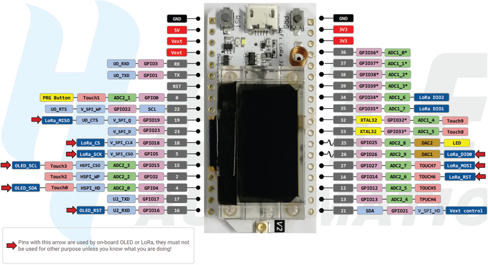
Figure 6: Wi-Fi LoRa 32 and pinout
Wi-Fi LoRa 32 uses dual-core 32-bit MCU and Ultra Low Power core ESP32 and LoRa node chip SX1276/SX1278 that are perfect for the LoRaWAN protocol. The ESP32 chip has a high level of low-power performance, including top-resolution clock-gate control, power-saving mode, and dynamic voltage management. Based on the LoRaWAN source code provided by Semtech, Wi-Fi LoRa 32 is made with many improvements to the low-power part of the code. Within one transmission cycle of the system, only a few milliseconds are working, and the rest of the time is in the deep sleep state.
In this section, we propose the algorithm for the WSN system based on the token ring in Zigbee network and polling mechanism in LoRa network. The program running on the proposed system is developed using C language in Arduino IDE.
Zigbee node is responsible for collecting LPG and CH4 concentration data in the air. In this model, two Zigbee clusters are configured for broadcast communication, so the Zigbee nodes have similar functions. We propose the token ring protocol, which uses a communication token flag. When the token flag is free (0), one Zigbee node can catch the transmission link and turn it into active status (1). After informing to other nodes the message “Pipe is Busy” and requiring them to wait, this node can communicate with the Zigbee-to-LoRa converter module. When the transmission is completed, this node informs the other nodes of the message “Pipe is Free” and resets token flag to zero. All the nodes will then transmit sensor information to the Zigbee-to-LoRa converter (see Fig. 7). To derive the most accurate sensor signals, we design the hardware using a 16-bit high-resolution Delta-Sigma ADC unit. A running average digital filter is also developed to average the measurements to eliminate hardware errors. We choose this filter because the 16-bit ADC module can measure signals with very high accuracy, and it is sensitive to noise. The averaging filter allows to store data samples in an array, update the array elements through each loop, and perform averaging to get accurate measurement values.

Figure 7: Flow chart of token ring protocol for Zigbee node
The technical working of Zigbee-to-LoRa converter is shown in Fig. 8. This converter transforms the Zigbee signal in a cluster that it manages into a LoRa signal and passes it to the LoRa gateway. It always listens to the Zigbee link. If a Zigbee node catches the token flag, then it establishes a link with that node and receives information from the sensor. When the communication process ends, the token flag is released. After the information is collected in the entire cluster, the converter waits for control signals from the LoRa gateway. If this command contains the right ID, then it will convert the collected data into LoRa form and pass the data to the gateway.
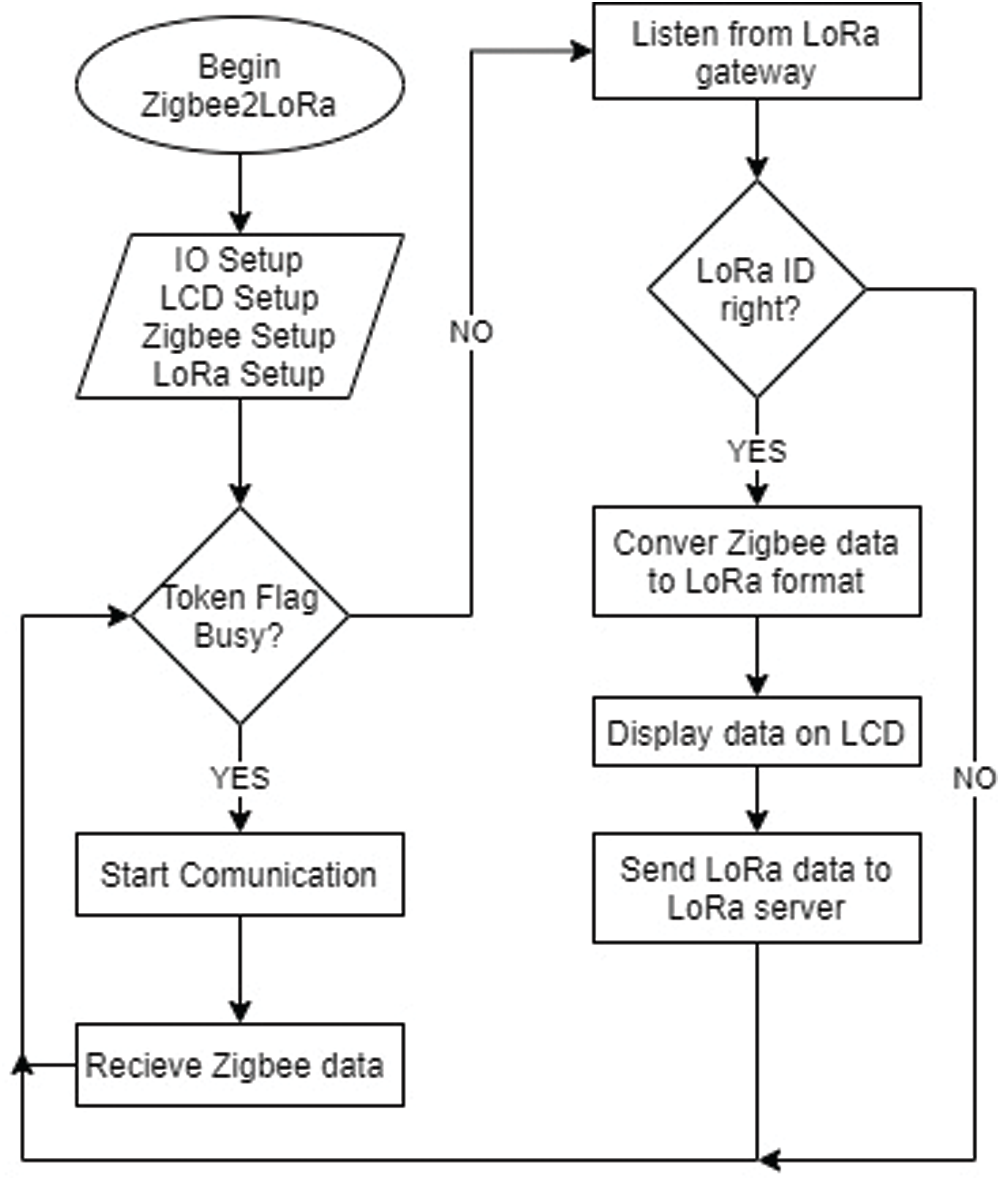
Figure 8: Flow chart of Zigbee-to-LoRa converter
Fig. 9 shows the flow chart of the software running on the agriculture LoRa node. In every 8-second cycle of collecting environmental data, this node goes into a deep sleep state and is only awakened by the timer interrupt. Environmental parameters including temperature, humidity, light intensity, and soil moisture are sent to the LoRa gateway. We use the checksum technique to ensure data integrity when communicating with the DHT11 sensor via the one-wire protocol as follows:
✓Byte 1: integer value of humidity (RH%)
✓Byte 2: decimal value of humidity (RH%)
✓Byte 3: integer value of temperature (T
Byte 4: decimal value of temperature (T
Byte 5: checksum. If Byte
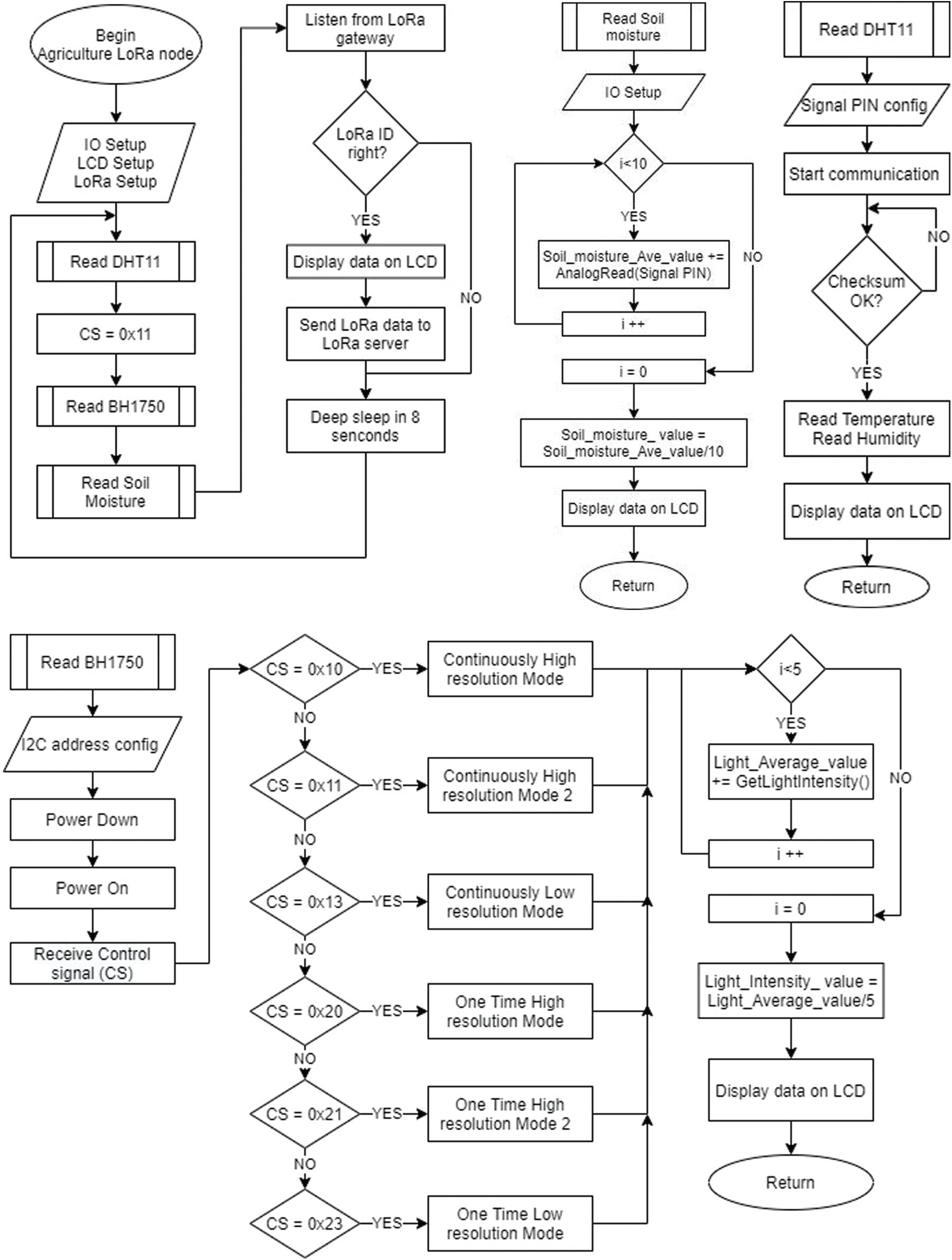
Figure 9: Flow chart of agricultural LoRa node
We use an averaged digital filter that smoothens the result measurements from light intensity and soil moisture. Specifically, we use a loop to collect between 5 and 10 samples of measurement data and average them. This operation helps the obtained data to be more stable and reliable. We use the control word
Fig. 10 shows the flow chart of the software running on the underwater LoRa node. Similar to other LoRa nodes, deep sleep and wake-up mechanisms are integrated into the software to ensure the node consumes as little energy as possible. This node collects underwater environmental parameters such as pH and turbidity and then sends these signals to the LoRa gateway. The turbidity sensor SEN0189 communicates with MCU via ADC process. We propose the recursive digital filters to increase the accuracy of the measurement. A recursive filter calculates a new, smoothed value (yn) by using the last smoothed value (yn −1) and a new measurement (xn), which is given as follows:
where w depicts the smoothing weighted factor.

Figure 10: Flow chart of underwater LoRa node
The weight is a value between 0% and 100%. When the weight is considerable (higher than 90%), the filter does not smooth the measurements very much but responds immediately to changes. If the weight is low (less than 10%), then the filter smooths the measurements significantly but does not respond quickly to changes. This filter does not need much memory (it only stores the last measurement), and we can modify the weight to control how much filtering is applied. It works well in battery-powered applications such as underwater environment because we do not need to make many measurements at once.
The pH sensor SEN0161 also communicates with MEC via ADC. We propose a two-step measurement procedure. In the first step, the system takes ten measurements and arranges them in order from big to small. In the second step, the system takes an average of six samples from the third sample to the eighth sample for more accurate measurements. The two most significant samples, i.e., first and second samples, and two smallest samples, i.e., ninth and tenth samples, are removed. The formula for converting the voltage value to the pH value is deduced from the experiment.
We utilize a synchronized 100 ms time slot for each measurement. For every 100 ms, we collect data of all sensors and forward the data to the Zigbee-to-LoRa converter. In case a node cannot provide the correct data in the time allowed, the preceding data sample is used instead.
LoRa gateway is responsible for collecting all the data of the system and sending the data to two Cloud servers: ThingSpeak and Blynk. The gateway uses a polling mechanism to request LoRa devices to send data back (see Fig. 11). The data are converted into a format following the MQTT protocol of ThingSpeak and Blynk’s Virtual Pin format for updating to the server.

Figure 11: Flow chart of the polling mechanism for LoRa gateway
In this section, we present the structure of the management software on the Blynk server [27,28] and ThingSpeak webserver [29–31], which are IoT analytics platform services that allow to aggregate, visualize, and investigate live data streams in the cloud.
Blynk is an application that runs on iOS and Android platforms to control and monitor devices via the Internet. Blynk supports various hardware like Arduino, Raspberry Pi, ESP8266 and many other popular hardware modules. Fig. 12 shows the Blynk Dashboard application smartphone interface that manages all the parameters in the system. The dashboard has three main function blocks, which are as follows:
✓Notification: The e-mail function allows the system to send collected sensor data to any e-mail. Typically, the system sets up e-mail to be sent at 0:00 daily. The e-mail content includes the ID of each node measured and all sensor parameters collected in real time. The Twitter function allows the system to post tweets describing system active status. The push notification function allows setting of alerts on smartphone. The report function allows to export information as real-time data stream.
✓Text display: This function allows to display system parameters in numerical format. Specifically, sensor parameters are shown on the screen, including temperature, light intensity, GAS, turbidity, humidity, and pH sensors and the cluster ID.
✓Graph display: This function includes two tabs. One tab shows the Zigbee cluster’s parameter graph, and the other tab shows the parameter graph for the LoRa cluster. It allows to display system parameters as real-time graphs. The real-time data can also be exported as a CSV file.

Figure 12: Blynk dashboard
Fig. 13 shows the structure of the ThingSpeak app. ThingSpeak is an open-source IoT application and API for storing and retrieving data using the HTTP and MQTT protocols over the Internet or the local area network. ThingSpeak enables creating sensor applications, logging and location tracking applications, and sensor networks with status updates to the server.
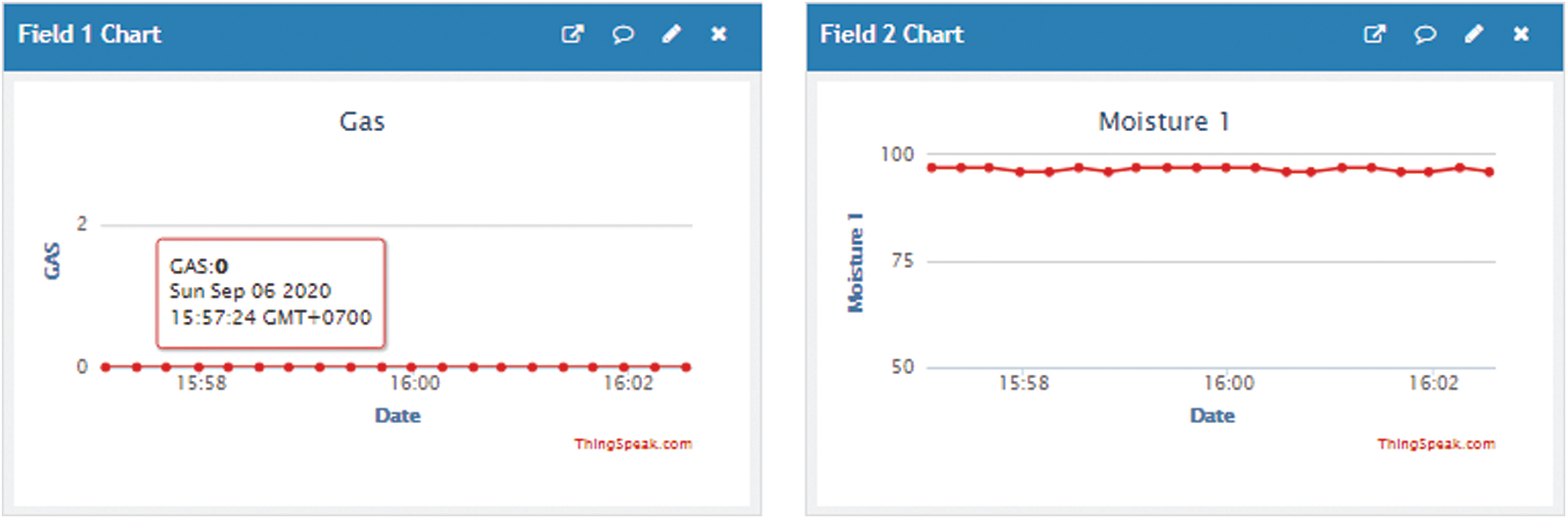
Figure 13: ThingSpeak app
ThingSpeak was initially launched by ioBridge in 2010 as a service to support IoT applications. ThingSpeak has integrated support from MathWorks’ MATLAB digital computing software that allows ThingSpeak users to analyze and visualize uploaded data with MATLAB without having to purchase a MATLAB license from MathWorks. Sensor data are displayed as a real-time graph.
This section explores three case studies, namely air quality monitoring, Agricultural monitoring, and Internet of Underwater Thing (IoUT) monitoring. In each case, we build management software, as shown in Fig. 14. In all three cases, we set up the Zigbee cluster to cover a radius of 100 m, whereas the LoRa cluster covers a 2 km range. The system operates under the token ring protocol in the Zigbee network and the polling mechanism in the LoRa network. The environment parameters are displayed on the Blynk interface and stored on the Blynk server. Users use the report function to download data in real time as CSV files.
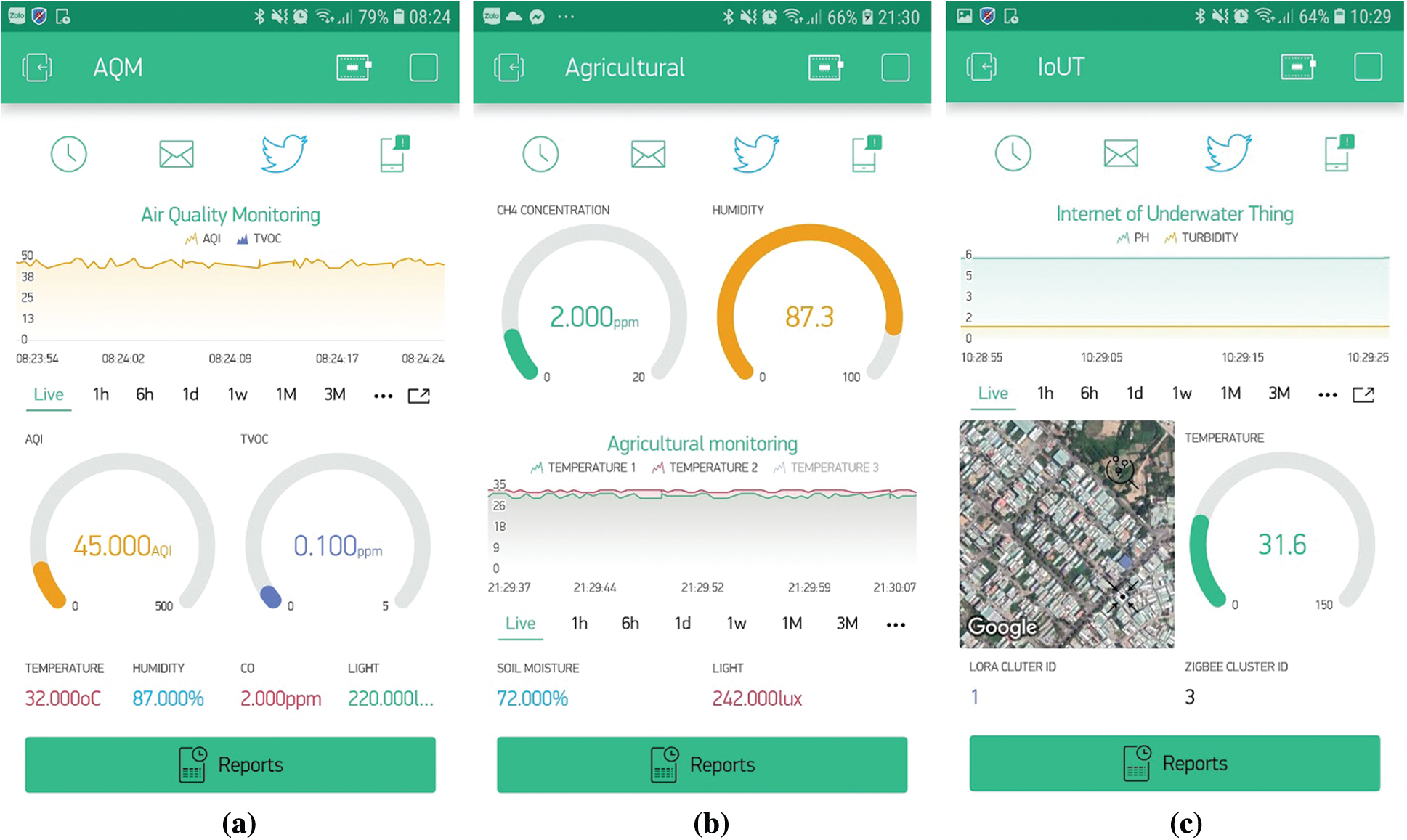
Figure 14: Blynk app: (a) Air quality monitoring, (b) IoUT monitoring, (c) agricultural monitoring
In this section, we evaluate system performance using the parameter of packet loss rate. The WSN system model based on Zigbee–LoRa is deployed to the real environment. The indoor LoRa gateway is located in a room connected to Wi-Fi, and the clusters and Zigbee-to-LoRa converter are located outdoors and moved to different locations. The system testing parameters are given in Tab. 1 [20].
In the first test scenario, we examine system performance in terms of packet loss. We set
Zigbee communication test phase: We fix the Zigbee-to-LoRa converter and LoRa gateway and set the position between them to 100 m. We also move the Zigbee cluster with increasing distance from 10 m to 5 km. Next, for each move, we set up the Zigbee cluster to send 1000 packets with ID number to the gateway. Finally, the Blynk interface is used for statistics on the number of packets received.
LoRa communication test phase: We fix the position of LoRa gateway and move the LoRa cluster with increasing distance from 10 m to 3 km. The next steps are the same as above.
Fig. 15 depicts the packet loss rate by a distance of Zigbee and LoRa communication. As expected, the larger the cluster distance, the higher the packet loss rate. In the proposed system, the optimal distance between the Zigbee cluster and Zigbee-to-LoRa converter is 630 m, and the optimal distance between the LoRa cluster and LoRa gateway is 3.7 km.
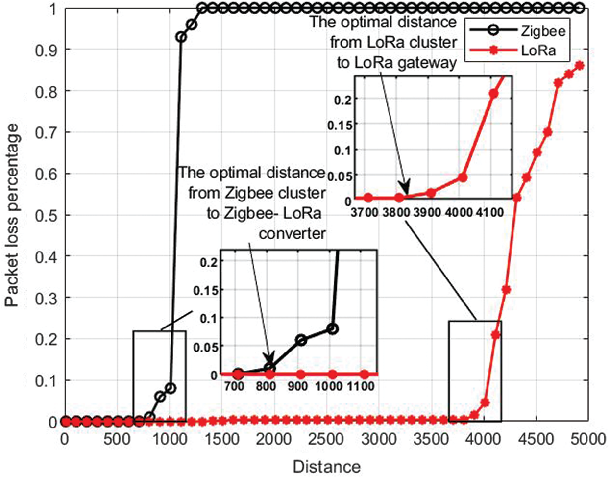
Figure 15: Packet loss rate by distance of Zigbee and LoRa communication
In the second test scenario, we evaluate system performance in terms of data transfer rate. We set the Zigbee-to-LoRa converter at a fixed location, that is, 500 m from the Zigbee cluster, and set all the LoRa clusters 2 km away from the LoRa gateway. This setup ensures the optimal communication distance for the proposed system. Next, we send 1000 packets with ID number at the cluster to the gateway and use Blynk for statistics.
Fig. 16 depicts the packet loss rate by bit rate (Rb). Using the formula for Rb given in Tab. 1, we set up different Rb to test the system with two schemes: using the proposed protocol, i.e., the token ring protocol combines the polling mechanism, and the protocol that directly transmits without feedback. In the case of using the proposed protocol, the packet loss rate is always < 0.5% when the Rb increases. The packet loss rate becomes very significant in the case when all clusters send broadcast in the system. This proves that the proposed protocol can improve the system performance.

Figure 16: Packet loss rate by bit rate of Zigbee and LoRa communication
This work presents the development of a Zigbee–LoRa-based, scalable, low-cost, and very low-power heterogeneous WSN for multiple functions in real time. The system contains two Zigbee clusters, two LoRa clusters managed by Zigbee-to-LoRa converters, and the LoRa gateway. In particular, Zigbee-to-LoRa converters are equipped with two Zigbee modules, providing better fault tolerance for the system. The system can communicate with many different types of sensors and be applied to various real environmental conditions. Management software built on ThingSpeak and Blynk provides an intuitive interactive environment. We propose a token ring protocol for the Zigbee cluster and the polling mechanism for the system’s LoRa cluster. The system’s data are synchronized to help the system achieve bit error rates lower than 0.5%. The experimental results demonstrate that the proposed protocol can improve system performance in terms of packet loss rate.
In future work, we will continue to improve the hardware system to enhance energy saving and increase transmission distance. We will also add functions of remote actuator control to the management software.
Funding Statement: The authors received no specific funding for this study.
Conflicts of Interest: The authors declare that they have no conflicts of interest to report regarding the present study.
1. A. Sampathkumar, S. Murugan, A. Elngar, L. Garg, R. Kanmani et al., “A novel scheme for an IoT-based weather monitoring system using a wireless sensor network,” in Integration of WSN and IoT for Smart Cities. Cham: Springer, pp. 181–191, 2020. [Google Scholar]
2. L. Garg, E. Chukwu, N. Nasser, C. Chakraborty and G. Garg, “Anonymity preserving IoT-based COVID-19 and other infectious disease contact tracing model,” IEEE Access, vol. 8, pp. 159402–159414, 2020. [Google Scholar]
3. L. K. Ketshabetswe, A. M. Zungeru, M. Mangwala, J. M. Chuma and B. Sigweni, “Communication protocols for wireless sensor networks: A survey and comparison,” Heliyon, vol. 5, no. 5, pp. e01591, 2019. [Google Scholar]
4. D. Kandris, C. Nakas, D. Vomvas and G. Koulouras, “Applications of wireless sensor networks: An up-to-date survey,” Applied System Innovation, vol. 3, no. 1, pp. 14–38, 2020. [Google Scholar]
5. M. Farsi, M. A. Elhosseini, M. Badawy, H. A. Ali and H. Z. Eldin, “Deployment techniques in wireless sensor networks, coverage and connectivity: A survey,” IEEE Access, vol. 7, pp. 28940–28954, 2019. [Google Scholar]
6. M. Jouhari, K. Ibrahimi, H. Tembine and J. Ben-Othman, “Underwater wireless sensor networks: A survey on enabling technologies, localization protocols, and internet of underwater things,” IEEE Access, vol. 7, pp. 96879–96899, 2019. [Google Scholar]
7. T. Rault, A. Bouabdallah and Y. Challal, “Energy efficiency in wireless sensor networks: A top-down survey,” Computer Networks, vol. 67, no. 12, pp. 104–122, 2014. [Google Scholar]
8. X. Feng, F. Yan and X. Liu, “Study of wireless communication technologies on internet of things for precision agriculture,” Wireless Personal Communications, vol. 108, no. 3, pp. 1785–1802, 2019. [Google Scholar]
9. S. Abraham and X. Li, “A cost-effective wireless sensor network system for indoor air quality monitoring applications,” FNC/MobiSPC, vol. 34, pp. 165–171, 2014. [Google Scholar]
10. W. Ma, Y. Wei, F. Sun and Y. Li, “Design and implementation of water saving irrigation system based on Zigbee sensor network,” IOP Conf. Series: Earth and Environmental Science, vol. 252, no. 5, pp. 52086, 2019. [Google Scholar]
11. U. D. Ulusar, G. Celik, E. Turk, F. Al-Turjman and H. Guvenc, “Practical performability assessment for ZigBee-based sensors in the IoT era,” in Performability in Internet of Things. Cham: Springer, pp. 21–31, 2019. [Google Scholar]
12. G. Sahitya, N. Balaji, C. D. Naidu and S. Abinaya, “Designing a wireless sensor network for precision agriculture using Zigbee,” in IEEE 7th Int. Advance Computing Conf., New York, US, IEEE, pp. 287–291, 2017. [Google Scholar]
13. V. Bianchi, P. Ciampolini and I. De Munari, “RSSI-based indoor localization and identification for Zigbee wireless sensor networks in smart homes,” IEEE Transactions on Instrumentation and Measurement, vol. 68, no. 2, pp. 566–575, 2018. [Google Scholar]
14. J. Jin, Y. Ma, Y. Zhang and Q. Huang, “Design and implementation of an agricultural IoT based on LoRa,” MATEC Web of Conf., vol. 189, no. 2, pp. 4011, 2018. [Google Scholar]
15. S. Liu, C. Xia and Z. Zhao, “A low-power real-time air quality monitoring system using LPWAN based on LoRa,” in 2016 13th IEEE Int. Conf. on Solid-State and Integrated Circuit Technology, New York, US, IEEE, pp. 379–381, 2016. [Google Scholar]
16. L. M. Fernández, J. Ramírez-Faz, M. Torres-Romero and R. López-Luque, “Proposal for the design of monitoring and operating irrigation networks based on IoT, cloud computing and free hardware technologies,” Sensors, vol. 19, no. 10, pp. 2318, 2019. [Google Scholar]
17. R. P Centelles, R. Meseguer, F. Freitag, L. Navarro, S. F. Ochoa, et al., “LoRaMoto: A communication system to provide safety awareness among civilians after an earthquake,” Future Generation Computer Systems, vol. 115, pp. 150–170, 2021. [Google Scholar]
18. A. Taha, M. F. Feteiha and W. Abdul, “Performance evaluation for LoRa transceiver,” International Journal of Computer Science and Software Engineering, vol. 8, no. 2, pp. 25–39, 2019. [Google Scholar]
19. P. Ragam and D. S. Nimaje, “Performance evaluation of LoRa LPWAN technology for IoT-based blast-induced ground vibration system,” Journal of Measurements in Engineering, vol. 7, no. 3, pp. 119–133, 2019. [Google Scholar]
20. A. Augustin, J. Yi, T. Clausen and W. M. Townsley, “A study of LoRa: Long range & low power networks for the internet of things,” Sensors, vol. 16, no. 9, pp. 1466, 2016. [Google Scholar]
21. E. González, J. C. Chafer, A. Romero, X. Vilanova, J. Mitrovics et al., “LoRa sensor network development for air quality monitoring or detecting gas leakage events,” Sensors, vol. 20, no. 21, pp. 6225, 2020. [Google Scholar]
22. A. Lavric and V. Popa, “Internet of things and LoRaTM low-power wide-area networks: A survey,” in Int. Symp. on Signals, Circuits and Systems, New York, US, IEEE, pp. 1–5, 2017. [Google Scholar]
23. M. L. Liya and M. Aswathy, “LoRa technology for internet of things (IoTA brief survey,” in Fourth Int. Conf. on IoT in Social, Mobile, Analytics and Cloud, New York, US, IEEE, pp. 8–13, 2020. [Google Scholar]
24. A. Raychowdhury and A. Pramanik, “Survey on LoRa technology: Solution for internet of things, intelligent systems,” in Technologies and Applications. Singapore: Springer, pp. 259–271, 2020. [Google Scholar]
25. A. I. Ali, S. Z. Partal, S. Kepke and H. P. Partal, “ZigBee and LoRa based wireless sensors for smart environment and IoT applications,” in 1st Global Power Energy and Communication Conf., New York, US, IEEE, pp. 19–23, 2019. [Google Scholar]
26. J. Shi, D. Mu and M. Sha, “LoRaBee: Cross-technology communication from LoRa to ZigBee via payload encoding,” in IEEE 27th Int. Conf. on Network Protocols, New York, US, IEEE, pp. 1–11, 2019. [Google Scholar]
27. P. Seneviratne, Hands-On Internet of Things with Blynk: Build on the Power of Blynk to Configure Smart Devices and Build Exciting IoT Projects. Birmingham, United Kingdom: Packt Publishing Ltd., 2018. [Google Scholar]
28. M. Sheth and P. Rupani, “Smart gardening automation using IoT with Blynk app,” in 3rd Int. Conf. on Trends in Electronics and Informatics, New York, US, IEEE, pp. 266–270, 2019. [Google Scholar]
29. L. D. Nardis, G. Caso and M. G. Benedetto, “ThingsLocate: A ThingSpeak-based indoor positioning platform for academic research on location-aware internet of things,” Technologies, vol. 7, no. 3, pp. 50, 2019. [Google Scholar]
30. M. A. Razali, M. Kassim, N. A. Sulaiman and S. Saaidin, “A ThingSpeak IoT on real time room condition monitoring system,” in IEEE Int. Conf. on Automatic Control and Intelligent Systems, New York, US, IEEE, pp. 206–211, 2020. [Google Scholar]
31. B. G. Rodríguez, J. S. Meneses and J. G. Rodriguez, “Implementation of a low-cost rain gauge with Arduino and Thingspeak,” in Int. Workshop on Soft Computing Models in Industrial and Environmental Applications, Cham, Springer, pp. 770–779, 2020. [Google Scholar]
 | This work is licensed under a Creative Commons Attribution 4.0 International License, which permits unrestricted use, distribution, and reproduction in any medium, provided the original work is properly cited. |