DOI:10.32604/cmc.2021.017008
| Computers, Materials & Continua DOI:10.32604/cmc.2021.017008 | |
| Article |
Improved Hybrid Precoding Technique with Low-Resolution for MIMO-OFDM System
1Department of Information and Communication Engineering, and Convergence for Intelligent Drone, Sejong University, Seoul, 05006, Korea
2Department of Computer Engineering, Sejong University, Seoul, 05006, Korea
*Corresponding Author: Hyoung-Kyu Song. Email: songhk@sejong.ac.kr
Received: 18 January 2021; Accepted: 20 February 2021
Abstract: This paper proposes an improved hybrid beamforming system based on multiple-input multiple-output orthogonal frequency division multiplexing (MIMO-OFDM) system. The proposed beamforming system improves energy efficiency compared to the conventional hybrid beamforming system. Both sub-connected and full-connected structure are considered to apply the proposed algorithm. In the conventional hybrid beamforming, the usage of radio frequency (RF) chains and phase shifter (PS) gives high power and hardware complexity. In this paper, the phase over sampling (POS) with switches (SW) is used in hybrid beamforming system to improve the energy efficiency. The POS-SW structure samples the value of analog beamformer to make lower resolution than conventional system. The number of output data in POS is decided by the resolution of POS system. The limited number of POS decides the resolution of antenna array and the values of POSs are designed from maximum and minimum phase angle antenna array. Energy efficiency without the phase shifter is high although channel capacity is nearly similar with conventional system. Also, the amplifier with POS-SW system is proposed to improve the BER performance. According to the data bits, the output signals of POS are decided. The system with 2, 3 and 4 bits is simulated to prove the proposed algorithm. In order to overcome the loss of low-resolution system, the amplifier with POS-SW system using channel information is proposed. The average sum-rate of 4 bits system shows the similar performance with the conventional hybrid beamforming system. This structure can play an important role by increasing the energy efficiency of the wireless communication system that many antennas are used. It is shown that the BER, average sum rate and energy efficiency of the proposed scheme are more improved than the conventional hybrid beamforming system.
Keywords: Hybrid beamforming; MIMO-OFDM system; analog precoding; POS-SW
Millimeter wave (mmWave) in wireless communication is a key feature in the fifth generation (5G) communication [1]. If high frequency band is used, the size of required antenna is decreased. The main components of hybrid beamforming are radio frequency (RF) chain and phase shifters (PSs). RF chain converts analog to digital data to transmit in low frequency and PSs control beam phase and amplitude to develop the shape of beam [2,3]. Digital beamforming system uses multiple RF chains with each antenna that requires high cost. But analog beamforming system consists of only one RF chain and multiple PSs that have an antenna array [4,5]. The main problem comes from the high-resolution phase constraints of the PSs. Hybrid beamforming has been proposed as a possible solution.
In mmWave communication system, conventional hybrid beamforming requires a large number of high-resolution PSs to construct analog beamformers to solve high power consumption and hardware complexity [6–9]. For limited technology of device, hybrid beamforming system has been studied to solve the issue in low-resolution PS system [10–12]. The 3-dimension (3D) beamforming is used for fully dynamic adaptation of the beamforming. The 3D beamforming based on 3D channel model is designed to support antenna configurations that are capable of adaptation in azimuth only. The hybrid beamforming is not limited to only mmWave band and can be used at other bands [13]. However, since the hybrid beamforming was originally developed to use the massive multiple-input multiple-output (MIMO) system, it is suited well in the mmWave band. For practical massive MIMO system, mmWave band is required for various reasons such as small antenna size and less RF chains, etc. Since massive MIMO systems require high data rate or reliability, many studies for the hybrid beamforming have been based on mmWave band.
The hybrid beamforming system has sub-connected or full-connected structure. In the sub-connected structure, each phase shifter is connected to each antenna array. On the other hand, in the full-connected structure, each phase shifter of RF chains is connected to one of antenna arrays. Also, the full-connected structure has higher hardware complexity and performance than sub-connected structure.
POS structure for hybrid beamforming system is proposed in [14]. In this paper, the proposed POS-SW system gives the higher energy efficiency than the conventional hybrid beamforming system. The number of output data in POS is decided by the resolution of POS system. Energy efficiency without the phase shifter is high although channel capacity is nearly similar with conventional system. Also, the amplifier with POS-SW system is proposed to surpass the conventional hybrid beamforming system with low-resolution.
In this paper, Section 2 shows the conventional hybrid beamforming system and Section 3 shows the proposed hybrid beamforming system with POS-SW. Section 4 shows the simulation results of proposed algorithm. Finally, Section 5 shows the conclusion of this paper.
2 Conventional Hybrid Beamforming in MIMO-OFDM System
2.1 Signal Model in Hybrid Beamforming
The Fig. 1 shows the multi-user OFDM-MIMO based on hybrid beamforming system, the digital precoding matrix at the k-th subcarrier,
where
where
where
And Ru[k] is the spectral efficiency of the k-th subcarrier as follows [7],
where

Figure 1: Multi-user MIMO-OFDM system based on hybrid beamforming
The channel model of the beamforming system uses 3D channel model [15] with zenith and azimuth angle on geometric stochastic model to determine accurate beamforming precoder. The Fig. 2 shows the angle of azimuth (
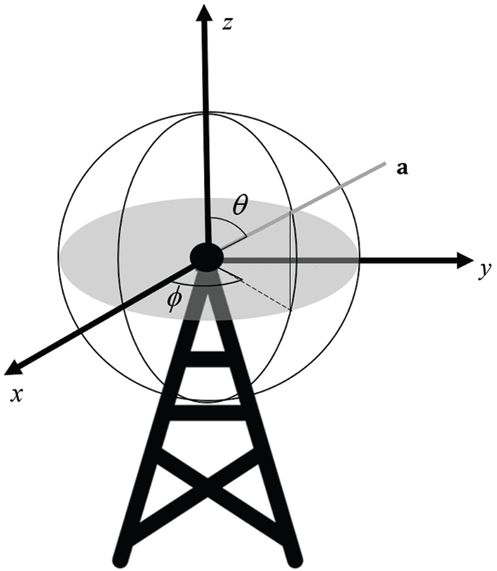
Figure 2: The zenith and azimuth angle of 3D channel model
Although the perfect channel information cannot be acquired, the perfect channel information is assumed to show the maximum performance of the proposed algorithm. If the specific technique for the channel estimation is used, the performance can be degradation. The multi-user channel model is composed of single-user channels as follows,
The 3D channel of the u -th user is suggested by the Saleh-Valenzuela model [16] as follows,
where
where
2.3 Energy Efficiency of PSs Network System
The energy efficiency (
where Pt is the transmitted energy, PRF is the energy consumption by RF chain and PPS is the energy consumed by PS. According to the number and the resolution of PSs, the power consumption and hardware complexity of the analog beamformer are increased. The adoption of a large-scale high-resolution PS network in existing solutions frustrates the real-world deployment of hybrid beamforming architectures in mmWave small cell networks. In real world, there are strict limitations on power consumption and hardware complexity in base stations and mobile devices.
3 Proposed Hybrid Beamforming System with POS-SW
To overcome hardware complexity of the conventional system, the POS-SW system is devised to reduce the resolution of the conventional hybrid beamforming system. The POS-SW is divided POS part and SW part in sub and full-connected structure.
Figs. 3 and 4 show the POS-SW system in sub and full-connected structure [8,19]. The RF chains and phase shifters are used in multi-user MIMO system with NT antenna array. The data streams are demodulated into sub-streams in encoder and each sub-stream is mapped to the phase shift keying (PSK) or quadrature amplitude modulation (QAM) symbol [20,21]. OFDM symbols with K sub-carriers are proceeded by inverse fast Fourier transform (IFFT) and combined with cyclic prefix (CP) before precoding in RF chain. In the analog precoding, the precoding matrix can be implemented by phase shifters with variable gain amplifiers. The two kinds of hybrid beamforming structures are considered in this paper.

Figure 3: The POS-SW system of sub-connected structure
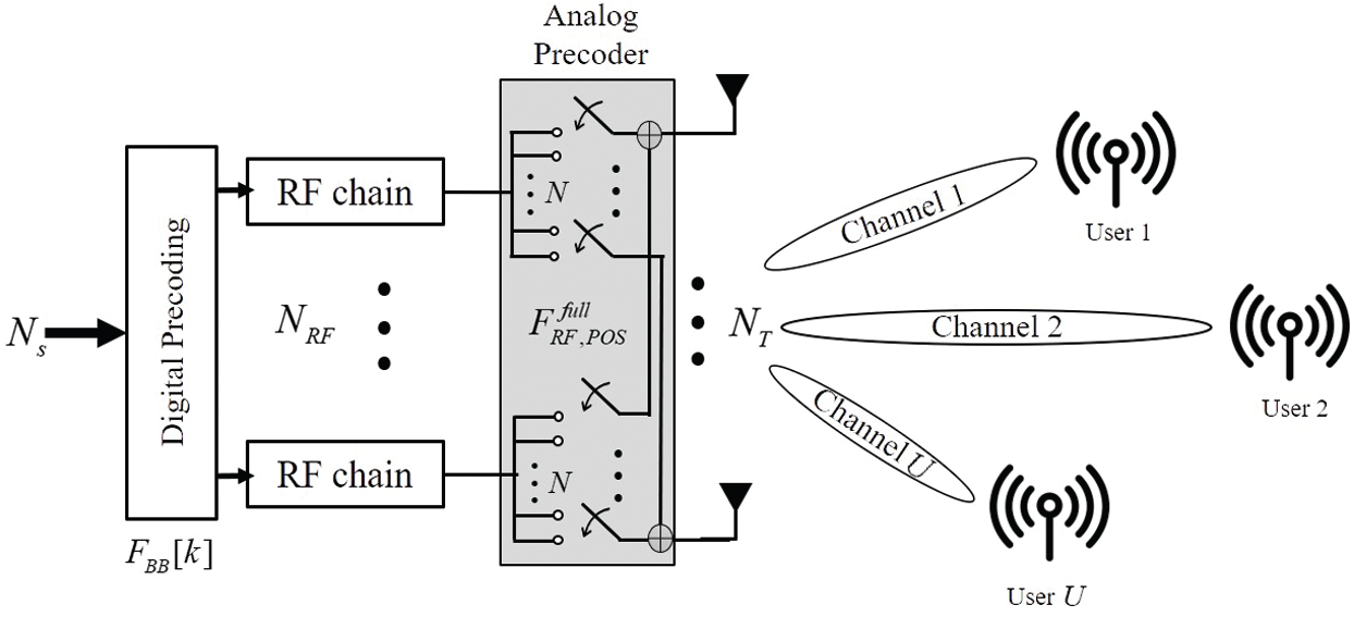
Figure 4: The POS-SW system of full-connected structure
The number of RF chains NRF and data streams Ns is same, i.e., NRF = Ns. The matrix of digital precoding in the k -th subcarrier,
where
Since each phase shifter in all RF chains is connected to one of antenna arrays in full-connected structure, the number of phase shifters,
where
3.2 Output Signals for Design of the Analog Precoder
Instead of the high-resolution PSs network in conventional beamforming system, each RF chain is connected to POS system which has output of N parallel signals with different phase. The N is the resolution of POS system. The N is changed according to the number of input signal bits. If 2 bits are used in POS system, the N = 22 output signals are consisted of the POS system in each RF chain. When the n bits are used, the resolution of N = 2n is applied. The output signals with N resolution are shown as follows,
where the vp, N is the N signals with expression of sequence. The elements of analog precoding matrix
The analog precoding matrix can be easily implemented by the parallel signals with vp, N. Each antenna is connected by a simple switch network. The Tab. 1 shows the sampling values according to the different resolutions.
Table 1: The sampling values according to the different resolutions

A detailed description of the iterative scheme at the k -th subcarrier is summarized as follows:
Data: Channel
Result:
(1) for k = 1:K
(2) initialize i = 0,
(3) While
(4)
(5)
(6) for
(7)
(8) end
(9) i = i + 1
(10)
(11) end
(12)
(13) end
(14)
(15) set vp, n according to resolution
(16)
The energy efficiency of proposed algorithm is different from the conventional system. The energy efficiency
where the PSW is the energy consumed by switches. The simple microstrip delay-lines can be utilized to realize the phase shifting stages. So, the energy consumption of POS part can be ignored. This scheme has significant advantage of low hardware complexity.
This POS-SW based hybrid beamforming architecture has low hardware complexity and power consumption. First, the variable gain amplifier (VGA) is used to provide different gain compensation for phases of each analog precoding matrix, which is connected with a different number of antennas. Because the limited number of resolutions N is employed, overall hardware complexity is low and power consumption is small. Moreover, each switch has low power consumption than PS of the conventional system. Second, the transmitter only needs the energy of POS part which has simpler hardware structure than conventional hybrid beamforming system. For example, POS with 2 bits can be easily realized by an inverter [22] and the POS with 4 bits can be implemented by using a sequence of phase-shifting stages [23].
The limited number of POS decides the resolution of antenna array and the values of POSs are designed from maximum and minimum phase angle antenna array. The proposed algorithm has high energy efficiency without phase shifter although channel capacity is nearly similar with conventional system.
3.3 The Amplifier with POS-SW System
The proposed POS-SW system has high energy efficiency with the loss of BER performance. The amplifier with POS-SW system is proposed to overcome the loss of performance. Fig. 5 shows the proposed amplifier with POS-SW system. The amplifier is connected to POS system to make strong norm of transmit signals.

Figure 5: The amplifier in POS-SW system of sub and full-connected structure
The transmit signal with amplifier gain g is calculated by the channel information as follows,
where g is the extra weight of transmit signal which is decided by the average of channel matrix
The amplifier gain g is calculated as follows,
The loss of BER exists in the low-resolutions system.
For evaluating the performance of the proposed algorithm, BER performances, average sum rate and energy efficiency are measured. The simulations in this proposed algorithm are performed in both sub-connected and full-connected structure of hybrid beamforming system. The simulation parameters in Tab. 2 are used. Both sub and full-connected structure use the same number of antenna. This paper uses the normal parameter in multi-user MIMO-OFDM wideband system [24]. The proposed algorithm can be applied with any generalization parameters. The antenna array in Eq. (7) is separated by a half wavelength distance with W = NT and H = 1. The minimum number of RF chain to receive the transmit signals in sub and full-connected structure has the same number of data streams. For measuring the energy efficiency, the power of three devices, PS, RF chain and switch are set. In the simulation, the power of phase shifter is 40 mW, RF chain is 300 mW and switch is 5 mW.
Table 2: Simulation parameters of the proposed POS-SW system

Figs. 6 and 7 show the energy efficiency between the proposed and conventional beamforming system in both two kinds of structure. Energy efficiency is calculated by Eq. (13) with the values in Tab. 2 in 30 dB SNR. The conventional system with infinite resolution of PSs networks in analog precoding uses modified PE-AltMin iterative algorithm. If different iterative algorithms are used for simulation, the performance shows the same tendency. Also, the conventional PSs network system picks all 64 points of FFT to make analog precoding matrixes. The conventional system with PSs network has high BER performance and average sum-rate. However, the PSs networks which estimate the phase in an infinite range consume a lot of energy. In the energy efficiency, the conventional system shows the lower performance than the proposed system.
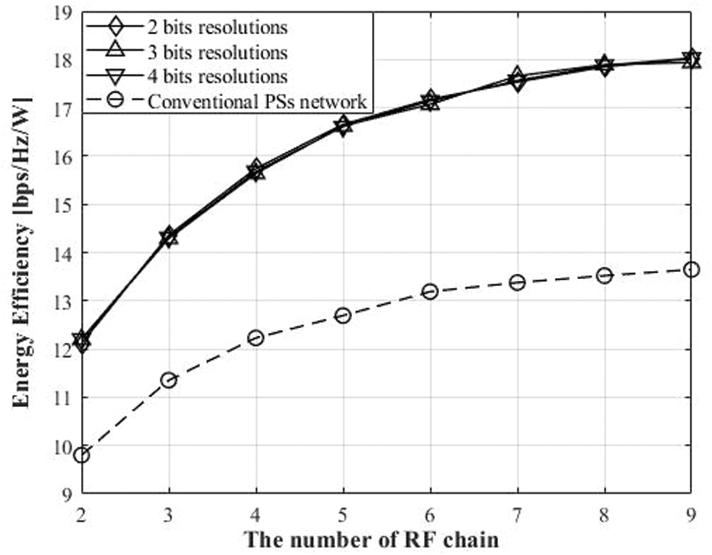
Figure 6: The energy efficiency of the POS-SW system with different resolutions and conventional system with infinite PSs in sub-connected structure

Figure 7: The energy efficiency of the POS-SW system with different resolutions and conventional system with infinite PSs in full-connected structure
The energy efficiency is improved when POS-SW systems with 2,3,4 bits are used. The similar performance is shown among the systems with three different bits. The high performance of energy efficiency gives advantage for designing the hybrid beamforming for wideband system. Specially, because of the frequency selectivity, path loss, delay spread, angle spread and the number of clusters, the large number of antenna array is required. The transmitter spends a lot of power consumption and cost in conventional system but the proposed POS-SW gives effective performance with high energy efficiency.
Fig. 8 shows the energy efficiency according to the different values of resolution in the proposed algorithm. The full-connected structure has higher performance than sub-connected structure. As the resolution increases, the number of POS values increases and improvement of performance is expected in both structures. The energy efficiency increases rapidly as the resolution of POS increases. However, as the resolution value increases, the width of the increase decreases after the resolution of 5 bits.
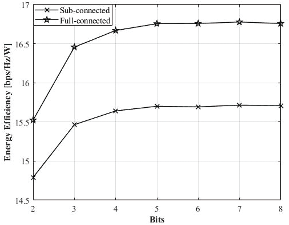
Figure 8: The energy efficiency of the POS-SW system with different resolutions
In this section, the simulation results of BER and average sum-rate are shown. Figs. 9 and 10 show the BER and the average sum-rate performance of sub-connected structure. And Figs. 11 and 12 show the BER and the average sum-rate performance of full-connected structure.

Figure 9: The BER performances of the POS-SW system with different resolutions and conventional system with high resolution PSs in sub-connected structure
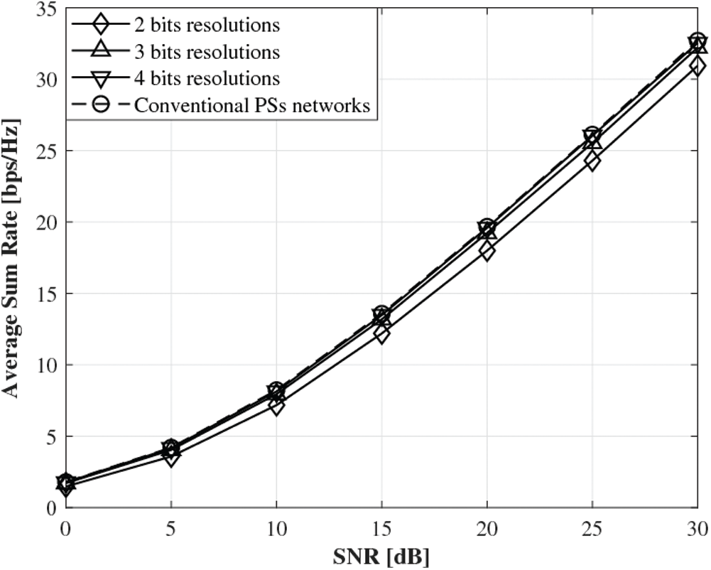
Figure 10: The average sum-rate performances of the POS-SW system with different resolutions and conventional system with high resolution PSs in sub-connected structure

Figure 11: The BER performances of the POS-SW system with different resolutions and conventional system with infinite PSs in full-connected structure

Figure 12: The average sum-rate performances of the POS-SW system with different resolutions and conventional system with infinite PSs in full-connected structure
The conventional hybrid beamforming system with PSs network has high resolution which uses the channel information. However, the proposed algorithm applies the low resolution POS-SW system to make low hardware complexity. In POS-SW system, the analog precoding matrix
4.3 BER Performance of the Amplifier POS-SW system
Figs. 9 and 11 show the BER performance of low-resolution system to make the higher performance of conventional system with high energy efficiency. Therefore this paper proposes amplifier model with POS-SW.
Figs. 13 and 14 show the BER performance using amplifier gain g in transmit signal as Eq. (16). The gain of amplifier g is decided by the channel information.
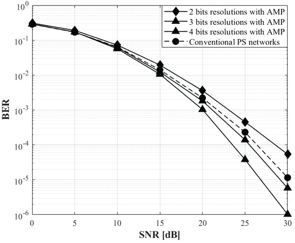
Figure 13: The BER performances of the amplifier with POS-SW in sub-connected structure
In Fig. 13, the improved performance is shown in the sub-connected structure. The POS system having 3 and 4 bits resolution with amplifier surpasses the performance of the conventional PS networks system with low-resolution. Moreover, Fig. 14 shows that the only 4 bits resolution with amplifier system overcomes the loss of the low-resolution system.
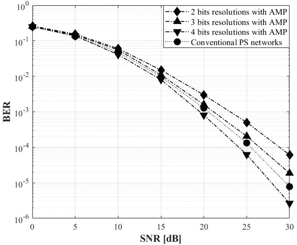
Figure 14: The BER performances of the amplifier with POS-SW in full-connected structure
In this paper, the advanced precoding technique is proposed to improve the energy efficiency. Both sub-connected and full-connected structure are considered to apply the proposed algorithm. The POS-SW system is proposed with low resolution of analog beamformer in the hybrid precoding technique for improving energy efficiency. The proposed POS-SW algorithm gives low hardware complexity and power consumption in wideband wireless communication system. According to the data bits, the output signals of POS are decided. The POS systems with the 2, 3 and 4 bits are simulated to prove the proposed algorithm. In order to overcome the loss of low-resolution system, the amplifier with POS-SW system using channel information is proposed. The trade-off is shown in the BER and average sum-rate performance. Specially, the average sum-rate of the system with 4 bits shows the similar performance with the conventional hybrid beamforming system
Funding Statement: This research was supported in part by Basic Science Research Program through the National Research Foundation of Korea (NRF) funded by the Ministry of Education (2020R1A6A1A03038540), and in part by R&D Program through the National Research Foundation of Korea (NRF) funded by the Ministry of Science and ICT (NRF-2020M3C1C1A02086427).
Conflicts of Interest: The authors declare that they have no conflicts of interest to report regarding the present study.
1. J. Zhang, E. Björnson, M. Matthaiou, D. W. K. Ng, H. Yang et al., “Prospective multiple antenna technologies for beyond 5G,” IEEE Journal on Selected Areas in Communications, vol. 38, no. 8, pp. 1637–1660, 2020. [Google Scholar]
2. E. Ali, M. Ismail, R. Nordin and N. F. Abdulah, “Beamforming techniques for massive MIMO systems in 5G: Overview, classification, and trends for future research,” Frontiers Inf Technol Electronic, vol. 18, pp. 753–772, 2017. [Google Scholar]
3. D. Zhu, B. Li and P. Liang, “A novel hybrid beamforming algorithm with unified analog beamforming by subspace construction based on partial CSI for massive MIMO-OFDM systems,” IEEE Transactions on Communications, vol. 65, no. 2, pp. 594–607, 2017. [Google Scholar]
4. J. Ro, W. Lee, J. Ha and H. Song, “An efficient precoding method for improved downlink massive MIMO system,” IEEE Access, vol. 7, pp. 112318–112326, 2019. [Google Scholar]
5. S. Lee, W. S. Lee, J. H. Ro, Y. H. You and H. K. Song, “Hybrid precoding technique with iterative algorithm for MIMO-OFDM system,” IEEE Access, vol. 8, pp. 171423–171434, 2020. [Google Scholar]
6. A. F. Molisch, V. V. Ratnam, S. Han, Z. Li, S. L. H. Nguyen et al., “Hybrid beamforming for massive MIMO: A survey,” IEEE Communications Magazine, vol. 55, no. 9, pp. 134–141, 2017. [Google Scholar]
7. O. E. Ayach, S. Rajagopal, S. Abu-Surra, Z. Pi and R. W. Heath, “Spatially sparse precoding in millimeter wave MIMO systems,” IEEE Transactions on Wireless Communications, vol. 13, no. 3, pp. 1499–1513, 2014. [Google Scholar]
8. C. Kim, T. Kim and J. Seol, “Multi-beam transmission diversity with hybrid beamforming for MIMO-OFDM systems,” in 2013 IEEE Globecom Workshops, Atlanta, GA, pp. 61–65, 2013. [Google Scholar]
9. X. Wei, Y. Jiang, Q. Liu and X. Wang, “Calibration of phase shifter network for hybrid beamforming in mmWave massive MIMO systems,” IEEE Transactions on Signal Processing, vol. 68, pp. 2302–2315, 2020. [Google Scholar]
10. F. Sohrabi and W. Yu, “Hybrid digital and analog beamforming design for large-scale MIMO systems,” in 2015 IEEE Int. Conf. on Acoustics, Speech and Signal Processing, Brisbane, QLD, pp. 2929–2933, 2015. [Google Scholar]
11. H. Li, M. Li, Q. Liu and A. L. Swindlehurst, “Dynamic hybrid beamforming with low-resolution PSs for wideband mmWave MIMO-OFDM systems,” IEEE Journal on Selected Areas in Communications, vol. 38, no. 9, pp. 2168–2181, 2020. [Google Scholar]
12. J. Mo, A. Alkhateeb, S. Abu-Surra and R. W. Heath, “Hybrid architectures with few-bit ADC receivers: Achievable rates and energy-rate tradeoffs,” IEEE Transactions on Wireless Communications, vol. 16, no. 4, pp. 2274–2287, 2017. [Google Scholar]
13. Y. Sun, Z. Gao, H. Wang, B. Shim, G. Gui et al., “Principal component analysis based broadband hybrid precoding for millimeter-wave massive MIMO systems,” IEEE Transactions on Wireless Communications, vol. 19, no. 10, pp. 6331–6346, 2020. [Google Scholar]
14. M. Li, Z. Wang, H. Li, Q. Liu and L. Zhou, “A Hardware-Efficient Hybrid Beamforming Solution for mmWave MIMO Systems,” IEEE Wireless Communications, vol. 26, no. 1, pp. 137–143, 2019. [Google Scholar]
15. F. Ademaj, M. Taranetz and M. Rupp, “3GPP 3D MIMO channel model: A holistic implementation guideline for open source simulation tools,” Journal on Wireless Communications and Networking, vol. 55, no. 1, pp. 1, 2016. [Google Scholar]
16. O. E. Ayach, S. Rajagopal, S. Abu-Surra, Z. Pi and R. W. Heath, “Spatially sparse precoding in millimeter wave MIMO systems,” IEEE Transactions on Wireless Communications, vol. 13, no. 3, pp. 1499–1513, 2014. [Google Scholar]
17. K. Hsu, C. Wang, Y. Lee and Y. Huang, “Low complexity hybrid beamforming and precoding for 2D planar antenna array mmWave systems,” in IEEE Workshop on Signal Processing Systems, Hangzhou, pp. 1–6, 2015. [Google Scholar]
18. X. Gao, L. Dai, S. Han, I. C. and R. W. Heath, “Energy-efficient hybrid analog and digital precoding for mmWave MIMO systems with large antenna arrays,” IEEE Journal on Selected Areas in Communications, vol. 34, no. 4, pp. 998–1009, 2016. [Google Scholar]
19. A. Alkhateeb and R. W. Heath, “Frequency selective hybrid precoding for limited feedback millimeter wave systems,” IEEE Transactions on Communications, vol. 64, no. 5, pp. 1801–1818, 2016. [Google Scholar]
20. L. Kong, S. Han and C. Yang, “Wideband hybrid precoder for massive MIMO systems,” in 2015 IEEE Global Conf. on Signal and Information Processing, Orlando, FL, pp. 305–309, 2015. [Google Scholar]
21. X. Gao, L. Dai, Y. Sun, S. Han and I. Chih-Lin, “Machine learning inspired energy-efficient hybrid precoding for mmWave massive MIMO systems,” in 2017 IEEE Int. Conf. on Communications, Paris, pp. 1–6, 2017. [Google Scholar]
22. A. S. Y. Poon and M. Taghivand, “Supporting and enabling circuits for antenna arrays in wireless communications,” Proc. of the IEEE, vol. 100, no. 7, pp. 2207–2218, 2012. [Google Scholar]
23. H. S. Hwang, J. H. Ro, Y. H. You, D. Hwang and H. K. Song, “Partial nulling regularized block diagonalization using unfair channel selection for post-coding with low-complexity,” Applied Sciences, vol. 10, no. 19, pp. 6809, 2020. [Google Scholar]
24. R. Méndez-Rial, C. Rusu, N. González-Prelcic, A. Alkhateeb and R. W. Heath, “Hybrid MIMO architectures for millimeter wave communications: Phase shifters or switches?,” IEEE Access, vol. 4, pp. 247–267, 2016. [Google Scholar]
 | This work is licensed under a Creative Commons Attribution 4.0 International License, which permits unrestricted use, distribution, and reproduction in any medium, provided the original work is properly cited. |