DOI:10.32604/cmc.2021.017177
| Computers, Materials & Continua DOI:10.32604/cmc.2021.017177 | |
| Article |
Cluster-Based Group Mobility Support for Smart IoT
1Department of Computer Science, University of Peshawar, Peshawar, 25121, Pakistan
2Department of Computer Science, Khushal Khan Khattak University, Karak, 27200, Pakistan
3Department of Informatics, King’s College London, UK
*Corresponding Author: Kanwal Imran. Email: kanwalim@uop.edu.pk
Received: 23 January 2021; Accepted: 25 February 2021
Abstract: IPv6 over Low Power Wireless Personal Area Network (6LoWPAN) connects the highly constrained sensor nodes with the internet using the IPv6 protocol. 6LoWPAN has improved the scalability of the Internet of Things (IoTs) infrastructure and allows mobile nodes to send packets over the IEEE 802.15.4 wireless network. Several mobility managements schemes have been suggested for handling the registration and handover procedures in 6LoWPAN. However, these schemes have performance constraints, such as increased transmission cost, signalling overhead, registration, and handover latency. To address these issues, we propose a novel cluster-based group mobility scheme (CGM6) for 6LoWPAN. To reduce the signalling cost in the CGM6 scheme, we propose to combine the functions of the Authentication, Authorization and Accounting (AAA) server and Local Mobility Anchor (LMA) in AMAG6 (
Keywords: 6LoWPAN; IoTs; mobility management; registration; handover; proxyMIPv6(PMIPv6)
The Internet-of-Things (IoTs) is the new rapidly evolving infrastructure that is predicted to connect 50 billion smart devices in 2025 [1,2], such as sensors, cameras, smart cars, and appliances. It is also predicted that 7 billion of these smart devices will be connected to 5G [3,4].
Sensors are the key components of IoT, and millions of them have been deployed worldwide for various applications such as collection and measurement of data from the network [5]. Sensors are autonomous devices and possess limited resources such as small storage capacity, low power battery, low data rate, and limited processing capability. IPv6 over Low Power Wireless Personal Area Networks (6LoWPAN) protocol standardized by the IETF (Internet Engineering Task Force) allows sensors with limited resources to transmit and receive massive data wirelessly using the internet protocol version 6 (IPV6) [6]. 6LoWPAN transmits and receives data in packets and consumes less energy [7]; Consequently, it saves battery power that can be used for a long duration. However, sensors in 6LoWPAN experience discontinuity during the handover procedure when they switch from one base station to another [8,9]. Which may cause disruption in services and leads to performance degradation [10,11]. Therefore, efficient, and reliable mobility support is required for low powered sensor nodes1 in 6LoWPAN [12,13].
To support mobility management, a working group NETLMM (Network-based localized mobility management) has developed a Proxy Mobile IPv6 (PMIPv6) protocol [14]. PMIPv6 has been recommended in several research articles for resource constrained mobile devices [15,16] due to its enormous benefits such as low signaling overhead. PMIPv6 protocol uses the Centralized Mobility Management (CMM) approach in which the role of centralized mobility agent is performed by a Local Mobility Anchor (LMA) [17].
The LMA in 6LoWPAN is represented using the term “LMA6.” It manages the binding information of recently attached authenticated nodes by registering them on the AAA (Authentication, Authorization and Accounting) server. The LMA6 is also responsible for controlling and managing the processing and communication of data packets. The mobile nodes1 attached to the MAG6 can be FFDs (Full Function Device) or RFDs (Reduced Function Device) [18]. The architecture of CMM is shown in Fig. 1a. The CMM schemes are expensive to implement due to higher expenditure and operational cost [19]. Furthermore, CMM is vulnerable to single point of failure and less efficient due to cumbersome and complicated registration and handover procedures [20].
To resolve the CMM scheme’s limitations, a Distributed Mobility Management (DMM) scheme has recently been proposed by IETF [21]. The architecture of DMM is shown in Fig. 1b. In the DMM approach, the LMA and MAG functions have been combined [22–24]. The process of handoff is performed between two neighboring MAGs [25,26]. Furthermore, DMM performs a handover procedure for each mobile node instead of a group of mobile nodes. The MAG6 in DMM Scheme is responsible for tracking the movement of mobile nodes. In the DMM scheme, 6LoWPAN gateways or MAG6 performs the function of both MAG and LMA. Mobile nodes communicate with the correspondent node via the previous MAG/LMA. In Fig. 1b it is denoted as “PMAG6.” After that, it handovers to the new NMAG6.
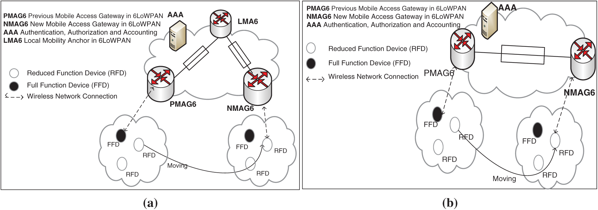
Figure 1: The architecture of (a) CMM Scheme and, (b) DMM Scheme in 6LoWPAN
Although DMM has resolved a few issues in CMM such as single point of failure and higher expenditure and operational cost. However, due to the handover procedure performed for every individual mobile node, it suffers from signaling overhead, leading to severe battery drainage. Therefore, an efficient and fast approach is required that can resolves the signaling overhead issue in 6LoWPAN.
In this paper, we propose a novel Cluster-based Group Mobility scheme for 6LoWPAN (CGM6). The main objective of CGM6 is to overcome the signaling overhead and ensures efficient communication among the 6LoWPAN nodes during the handover process. In this approach, we introduce a new entity called AMAG6 that combines the functions of AAA server and LMA. AMAG6 is responsible for both binding and authentication process. It manages the authentication process for the group of nodes simultaneously via a group leader. The main aim of group authentication and binding is to reduce the signaling cost. AMAG6 exchanges its information with its neighboring AMAG6 during the handover process as a cluster head to reduce the number of control messages. AMAG6 is also responsible for intra-cluster and inter-cluster communication of mobile nodes. Each sub-domain is represented as a cluster comprised of a group of mobile nodes, leaders, and AMAG6 acts as a cluster head.
We summarize our contributions in this article as follows:
• In this paper, a comprehensive mobility management architecture is proposed based on DMM scheme for 6LoWPAN. The proposed protocol performs handoff management by organizing MAGs in clusters. In this regard, no additional component has been added to existing DMM scheme, and functional entities are re-arranged to achieve a better performance in terms of signaling cost.
• A group binding strategy is proposed for 6LoWPAN. The main objective of the binding strategy is to reduce the signaling cost via binding the group of mobile nodes.
• The proposed CGM6 is simulated and evaluated analytically by comparing it against the state-of-the-art mobility management schemes. Our simulation results show that CGM6 reduces the handoff latency by 32%, registration delay by 11% and transmission cost by 37%.
The remainder of this article is organized as follows: Section 2 describes the proposed CGM6 scheme, including its architecture, initial registration process and handover phase. Section 3 discusses the performance of the considered schemes in terms of the handover delay, registration delay and transmission cost. Section 4 presents numerical results. Section 5 finally concludes our research efforts.
2 Proposed Cluster-Based Group Mobility Scheme for 6LoWPAN (CGM6)
In this section, we introduce our proposed CGM6 scheme. First, we introduce the architecture of CGM6 for 6LoWPAN. Then, registration and handover procedures are discussed in detail.
The architecture of CGM6 is shown in Fig. 2. The CGM6 consists of two types of mobile nodes called Host and Group Leader. The Host is an RFD that collects sensory information. The Group Leader is responsible for routing packets, exchange messages among other entities of CGM6 and control the signals with the AMAG6 on behalf of other nodes of its group. It is denoted as FFD6 in the Fig. 2. The Group Leader is a fully functional device and possesses strong storage and processing capacity. In the case of multiple FFD6s in CGM6, the mobile node with minimum distance from the base station is selected as a Group Leader. To reduce the registration and handover delay, AMAG6 maintains information of all the nodes in the group. The mobile node desires to register with the Group Leader broadcasts a registration request in its group. The Group Leader responds with registering the requesting mobile node. After receiving all the mobile nodes’ registration requests, the Group Leader integrates its information and generates a list. After then, it sends the list to the AMAG6 through RS (router solicitation) message. On receiving the RS message from the Group Leader, the AMAG6 verifies the validity of mobile nodes and sends back the list of registered nodes to the Group Leader through RA (router advertisement) message. The Group Leader then sends a local registration message to all valid group members of its group.
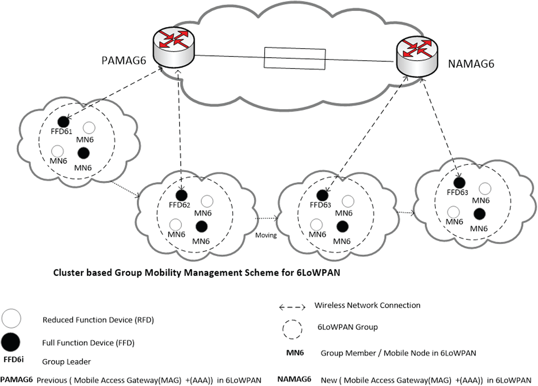
Figure 2: The architecture of CGM6 in 6LoWPAN
In the proposed CGM6 scheme, AMAG6 is responsible for authentication and binding of a group of mobile nodes via the FFD6 (Group Leader). The AMAG6 exchanges its information with its neighboring AMAG6 instead of LMA. This helps in reducing the number of control messages leading to low signaling overhead. AMAG6 handles the mobility of mobile nodes in both intra-cluster and inter-cluster scenarios. Each sub-domain is represented as a cluster comprised of a group of mobile nodes, their leaders with one AMAG6 acting as their cluster head.
At the network access level, the AMAG6s are distributed across the CGM6 architecture. The mobile nodes register with the AMAG61 through their Group Leader, as depicted in Fig. 3a. During the mobility, the mobile node configures a new address based on its network prefix. Then, it changes its point of attachment to another AMAG6 (AMAG62). Further, it also retains the previous address on the initiation of handover (Fig. 3b). To bind with the AMAG62, the mobile node generates a BU message. Then, it establishes a new session through AMAG62 with newly configured address Fig. 3c. AMAG62 sends a message to AMAG61 by using the previous address data of the mobile node to update the routing and mobility status on completion of the handover. IP handover from AMAG61 to AMAG62 is completed through the acknowledgement message. The same procedure is performed during the movement of MN6 and handover initiates towards the AMAG63 (Fig. 3d). Fig. 3e shows, handover completion and then session continued through the AMAG63.
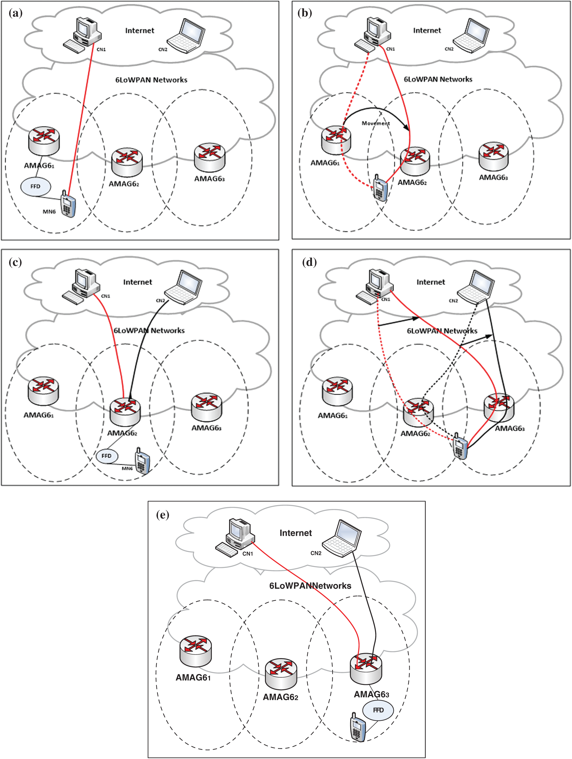
Figure 3: Architecture of the CGM6: (a) MN6 communication with CN1 via AMAG61, (b) handover initiates to AMAG62 during the movement of MN6, (c) new session established through the AMAG62 with CN2 (handover Complete), (d) handover initiates towards the AMAG63 during the movement of MN6, (e) session continued through AMAG63 (handover complete)
The registration phase of the CGM6 is depicted in Fig. 4. In this scheme, AAA and LMA functions are incorporated in the MAG to create a new entity called AMAG6. The registration process is performed as follows:
Step1: The MN6 attached to an AMAG6 through its Group Leader FFD6 sends a Router Solicitation (RS) message to the AMAG6.
Step2: After receiving the RS message, the AMAG6 returns a RA (Router Advertisement) message to the corresponding MN6 via its FFD6.
Step3: Then, the MN6 sends Binding Update (BU) messages to AMAG6 through its group leader FFD6.
Step 4: After receiving the BU message, the AMAG6 sends back Binding Acknowledgement (BA) message to bind the MN6 through its Group Leader FFD6.
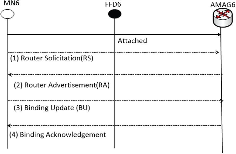
Figure 4: Registration phase of CGM6 in 6LoWPAN
Our proposed scheme describes two scenarios for signaling communication: (i) Intra-cluster, and (ii) Inter-cluster. The handover phase is illustrated in Fig. 5.
2.3.1 Intra-Cluster AMAG6 Communication
In the intra-cluster handoff process, the MN6 moves within the same cluster and same AMAG6. AMAG6 controls the communication process for the group of mobile nodes through their leaders, i.e., FFD61 to FFD62. When an MN6 is detached from the Group Leader FFD61 and attached to the Group Leader FFD62, following steps are carried out (Fig. 5):
Step1: For the detachment purpose, the FFD61 sends a local de-registration message to the nearest AMAG6.
Step2: Then, FFD62 sends a Proxy Binding Update (PBU) message to bind with AMAG6. Then, MN6 get registered with a new group leader.
Step3: On receiving the PBU message, the AMAG6 sends back Proxy Binding Acknowledge (PBA) messages to a new Group Leader. After then, the handover tunnel is created to tunneling the data packets.
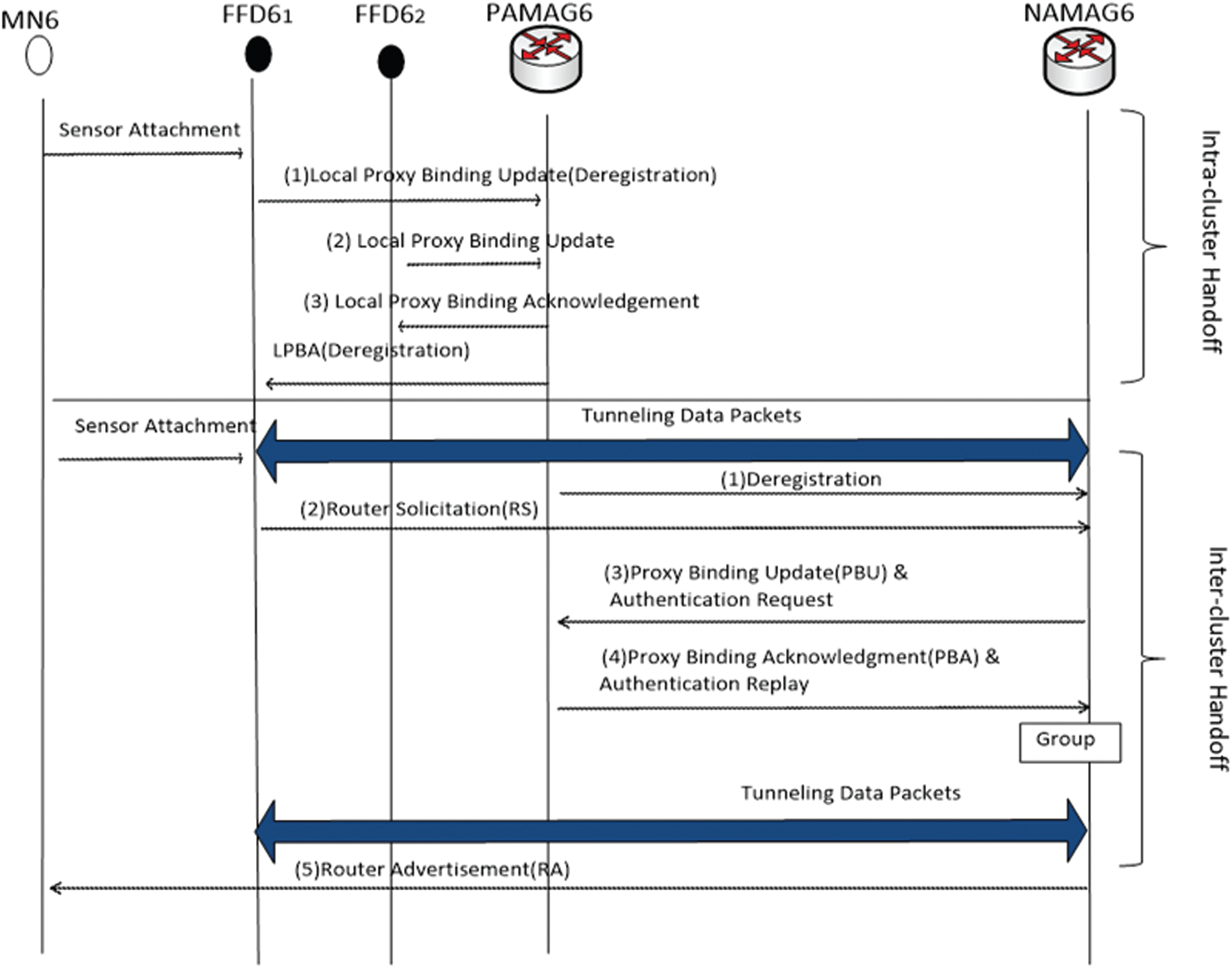
Figure 5: Handover Phase of CGM6 in 6LoWPAN
2.3.2 Inter-Cluster AMAG6 Communication
In the inter-cluster scenario, MN6 moves from one AMAG6 to other AMAG6 of another cluster. During the inter-cluster communication, the following steps are performed:
Step1: The mobile node MN6 detaches from the previous AMAG6 (PAMAG6) and attached to a new AMAG6 (NAMAG6) as shown in Fig. 5.
Step2: Then, it sends an RS message via its Group Leader FFD61 to the NAMAG6.
Step3: The NAMAG6 exchanges the binding (PBU and PBA) and the authentication (AAA request and AAA reply) messages with the PAMAG6 using the same control message to achieve the minimum handoff delay.
Step4: A handover tunnel is established between NAMAG6 to MN6 via its Group Leader.
Step5: Finally, the NAMAG6 replies to the MN6 with the RA message.
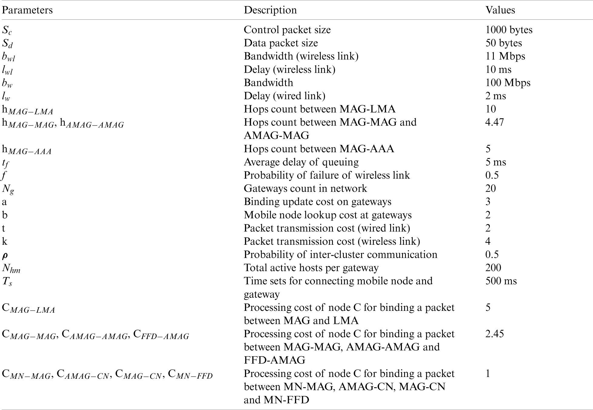
This section evaluates the proposed CGM6 scheme by comparing it with CMM and DMM mobility management schemes for 6LoWPAN. All schemes are analyzed and compared based on the registration delay, handover delay & cost analysis, which are considered key performance metrics. Fig. 6 presents the network model, we used for the performance evaluation. Tab. 1 summarizes the notations used in the analysis.
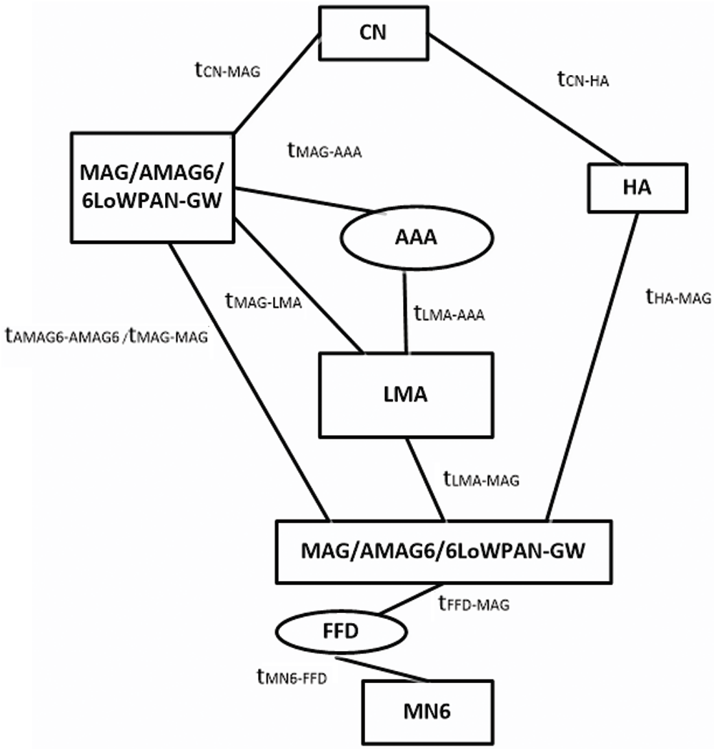
Figure 6: Network model
Table 1: Parameters used for numerical analysis
In Eq. (1),
The Eq. (2) represents the transmission latency of a message of size ‘s’ when it travels from the node (x) to node (y) via a wired link.
The Total Cost (TC) in terms of signaling cost is derived for comparing the performance of CGM6 e with the state of the art. TC is calculated by adding the Binding Update Cost (BUC) with Packet Delivery Cost (PDC).
3.2 Analysis of Registration Latency
In this section, we will present the registration latency analysis of CMM, DMM, and CGM6 in 6LoWPAN.
3.2.1 Registration Latency of CMM in 6LoWPAN
When mobile node is attached to MAG6, it sends a RS message to MAG6 through FFD6. The MAG6 then performs authentication and reply operations with AAA server. Then the MAG6 exchanges PBU & PBA signals with LMA6. After receiving the PBA message, the MAG6 returns an RA message to mobile node. The registration latency of CMM is represented as:
3.2.2 Registration Latency of DMM in 6LoWPAN
When a mobile node is attached to a gateway (MAG6/LMA6), it sends an RS message to MAG6/LMA6 through the FFD6. Then, MAG6/LMA6 performs authentication request and reply operation with the AAA server. After performing the authentication, MAG6/LMA6 responds through a RA message to the mobile node. Based on the above scenario, registration latency of DMM is represented as:
3.2.3 Registration Latency of CGM6
In our proposed CGM6 scheme, group communication is done through the Group Leader. During the deployment of mobile nodes across the network, each MN6 in a group must register itself with the AMAG6. The MN6, as a group member, sends a message to the Group Leader FFD6. Next, FFD6 generates a list of all attached nodes and send it to the AMAG6 through an RS message. After performing the authentication process, the AMAG6 sends an RA message to the MN6 through its FFD6. The registration latency of proposed CGM6 is expressed as:
3.3 Analysis of Handover Latency
Handover latency is defined as the transmission period when a mobile node cannot receive the packets from the previous MAG6 or when a mobile node receives the first packet from the new MAG6.
3.3.1 Handover Latency of CMM in 6LoWPAN
When a mobile node is attached to a new MAG6(NMAG6), it sends an RS message to the NMAG6 through the FFD6. The NMAG6 exchanges authentication request and sends reply signal to the AAA server. After then, it performs PBU and PBA operations with the LMA6. The NMAG6 sends an RA message to the MN6. On receiving the PBA message, signaling delivered to a mobile node through the NMAG6. The handover latency of CMM6 is written as:
3.3.2 Handover Latency of DMM in 6LoWPAN
In this scheme, a mobile node attached to a gateway NMAG6/LMA6 must send an RS message to the NMAG6/LMA6 through the FFD6. Then, NMAG6/LMA6 exchanges authentication request and reply message with the AAA server. After the authentication process, NMAG6/LMA6 performs PBU and PBA operations with PMAG6/LMA6 to establish a handover tunnel. The handover latency of DMM is given below:
3.3.3 Handover Latency of Proposed CGM6 Approach
In this section, we describe the exchange of signaling messages for inter-cluster and intra-cluster scenario for CGM6 scheme.
(a) Intra-Cluster AMAG6 Mobility
In the intra-cluster handoff process, MN6 moves in the same cluster under the same cluster head MAG6. AMAG6 controls the communication process within a group of mobile nodes through its leader (FFD61 to FFD62).
(b) Inter-Cluster AMAG6 Mobility
This scenario describes the mobility of a mobile node between two different clusters under the different AMAG6s. Once NAMAG6(New AMAG6) receives packets from the MN6 via the RS message. Then, NAMG6 performs authentication process with PBU and also performs PBA operations with PMAG6 for groups of nodes. Then NAMAG6 sends a RA message after establishing a tunnel to MN6 through their group leaders FFD6. The handover latency of CGM6 is written as:
3.4 Analysis of Transmission Cost (TC)
The TC is calculated by adding the BUC with the PDC. Next, we evaluate TC for CMM, DMM and proposed CGM6.
3.4.1 TC Analysis of CMM in 6LoWPAN
For CMM, the process of binding update requires the establishment of connection between the mobile node and the MAG6 which further requires Ts. For performing the authentication operation of MN6 2tCMAG−AAA +2tCLMA−AAA is required. For exchanging the PBU and PBA with the LMA6
The process of packet delivery in CMM initiates by the MN6 which sends the packet from MN6 to its LMA6 through the MAG6; which further requires k CMN−MAG +2tCMAG−LMA. The LMA6 then searches for packet binding entry for the corresponding nodes addresses and requires the
Therefore, the TC of CMM6 can be expressed as:
3.4.2 TC Analysis of DMM in 6LoWPAN
In the DMM scheme, LMA6 and MAG6 functions are combined and the handoff procedure is performed between two neighboring MAG6 leading to reduction in LMA processing cost. The process of binding update comprises the establishment of the connection between the MN6 and the MAG6 which requires Ts, and exchanging the authentication and binding messages (2t CMAG−AAA, 2tCMAG−MAG) between two neighboring MAG6.
The packet delivery process in DMM6 is done between two neighboring MAG6 and written as:
As a result, TC of DMM6 can be written as:
3.4.3 TC Analysis of Proposed CGM6 Approach
The proposed CGM6 scheme describes two scenarios for mobility, namely, the intra-cluster & inter-cluster mobility, respectively. For computing the TC, we considered both scenarios using the probability value (
(a) Intra-cluster Mobility
In this scenario, the MN6 moves from one FFD6 to another FFD6 within the same AMAG6. The AMAG6 processing cost is doubled due to performing the authentication and registration functions (
For the PDC a packet is sent from the MN6 through FFD6 (group leader) to its AMAG6 (k CMN−LD +k CLD−AMAG +k CAMAG−CN). The processing cost of AMAG6 is
Thus, the intra-cluster PDC can be written as:
Accordingly, the TC of CGM6 for intra-cluster mobility can be expressed as:
(b) Inter-Cluster Mobility
In this scenario, the MN6 moves between AMAG6 that are present in different clusters. AMAG61 exchange its information with its neighboring AMAG62 during handover process as a cluster head. The AMAG61 sends a binding update to another AMAG62 through a group leader is (2k CLD−AMAG +2tCAMAG−AMAG), and AMAG6 processing cost is
After receiving a packet from the MN6, the group leader forwards the packet to the AMAG6, which requires
The TC for intra-cluster and inter-cluster scenarios of proposed CGM6 scheme can be evaluated by using the inter-cluster probability parameter
4 Simulation Results and Discussions
In this section, we discuss our simulation results. For the comparison of mobility management schemes, the equations presented in Section 3 are used as a performance criterion. Next, we discuss our simulation environment, then detail analysis on the obtained results is presented. The parameters and their corresponding values are given in Tab. 2.
Table 2: Simulation parameters
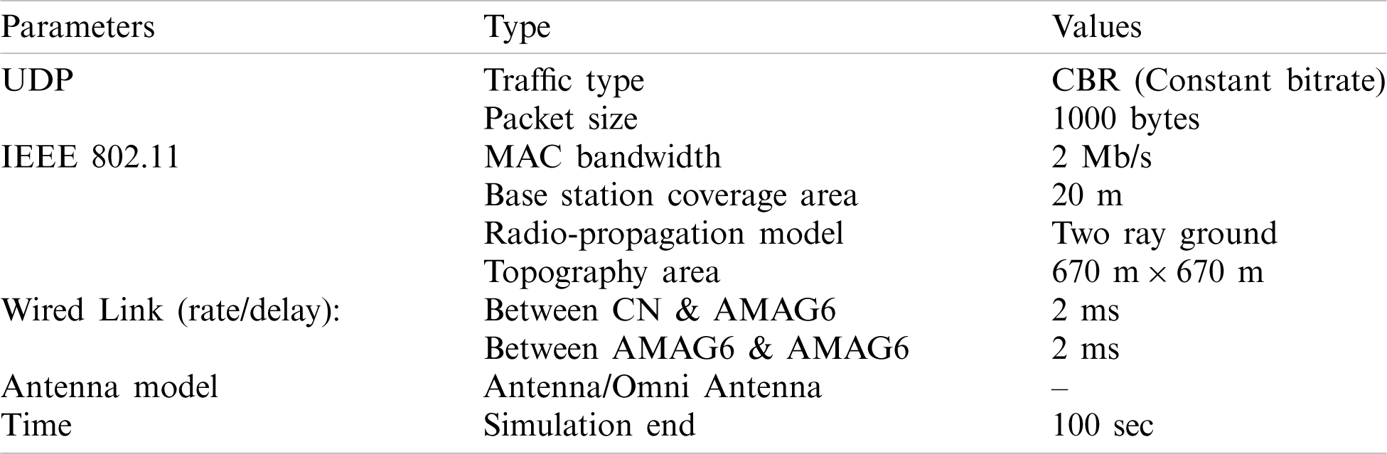
The simulation environment used for evaluating the proposed scheme CGM6 is Network Simulator version 2 (NS2). The National Institute of Standards and Technology (NIST) package based on PMIPv6 is used with simulation platform ns-2.29 (network simulator version 29) running on Ubuntu 17.10. A patch (nist-pmip6-6lowpan-ns_2.29-ubuntu12_i386.deb) which integrates 6LoWPAN and PMIPv6 is used for the simulation. All simulations are done on an Intel machine with a 2.40 GHz Core i3-3110 and 4 GB of RAM. The AWK scripting language in NS2 is used for text processing and extraction of tr (tracing) file. NAM (Network Animator) is used for the NS2.29 simulation [27]. Results are simulated by using Xgraph.
We compared the proposed mobility management scheme with the existing 6LoWPAN mobility schemes: CMM and DMM. We used registration latency, handover latency and Total cost as our performance parameters.
Fig. 7 shows the impact of wireless links delay on registration latency for CMM, DMM, and CGM6 schemes in 6LoWPAN. We can observe from the figure that the registration latency increases as the wireless link delay increases. However, CGM6 shows better performance. The implication is that, during the registration process, both CMM and DMM schemes exchange extra signaling messages over a wireless link in 6LoWPAN.
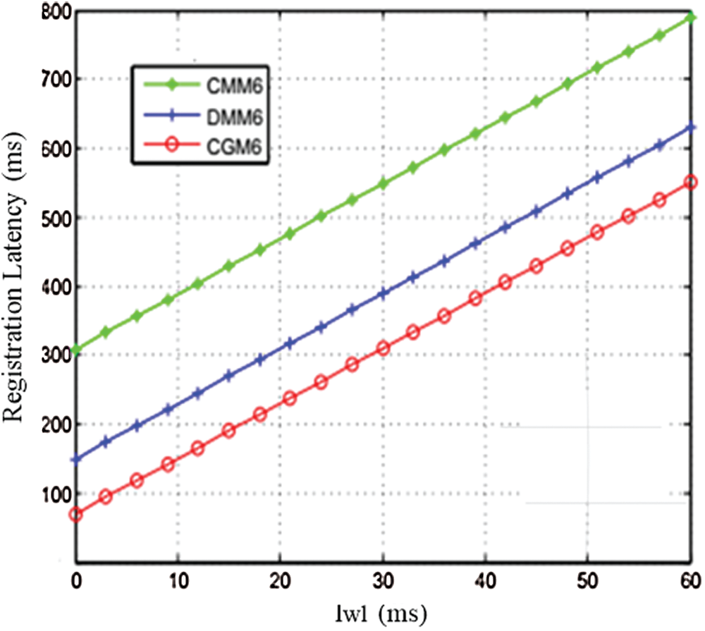
Figure 7: Effects of wireless link delay (lwl) on registration latency
For instance, in CMM scheme control signals are exchanged from MAG6 to LMA6 and AAA, and in CMM scheme control signals are exchanged from MAG6 to AAA. While, in the CGM6 scheme, the authentication and binding operations are performed within the AMAG6. This avoids signaling overhead during the registration process leading to better performance.
Figs. 8a and 8b shows the effects of wireless link delay (lwl) and average queuing delay (tf) on handover latency for CMM, DMM, and CGM6 schemes in 6LoWPAN. It can be observed from the figure that handover latency increases as wireless link delay and queuing delay increase. Our CGM6 scheme performs better than DMM and CMM. The reason is that, in CGM6 scheme, authentication and binding operations are combined in AMAG6. This avoids the extra signal exchange activities among the nodes in 6LoWPAN. It can also be observed from the Fig. 8 that CMM scheme shows worst performance than DMM and CGM6. This is due to the relief in LMA operations and integration of the authentication and binding operations in AMAG6. The implication is that the CMM scheme consumes more time in processing as compared to two others schemes.
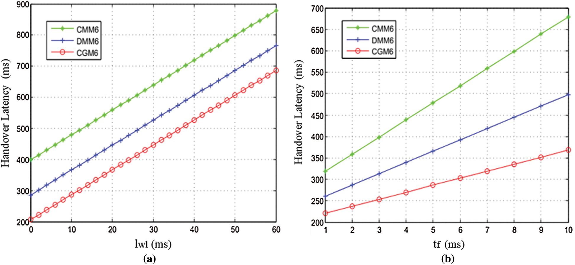
Figure 8: Effect of (a) wireless link delay (lwl) and (b) average queuing delay (tf) on handover latency
4.4 Analysis of Transmission Cost
Fig. 9a depicts the impact of inter-cluster operations on the Total Cost by varying the probability parameter (
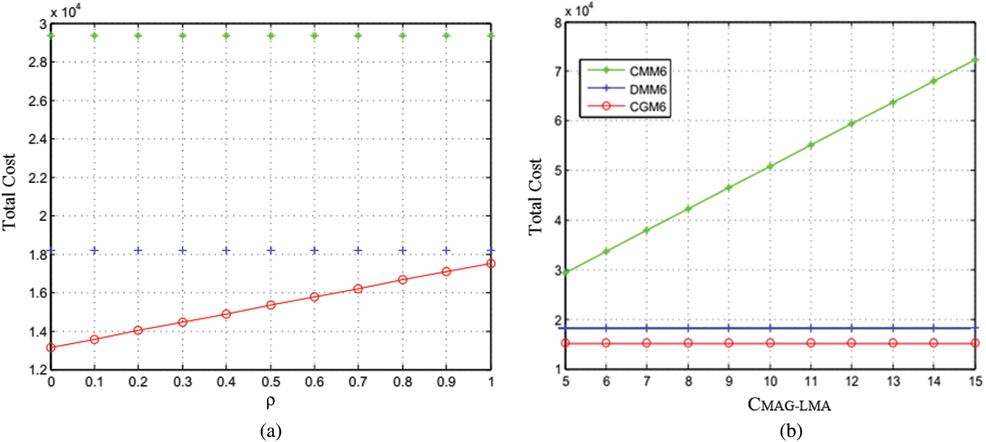
Figure 9: Effects of total cost on (a) inter-cluster operation (
The impact of wireless link delay on total cost is shown in Fig. 10a. As the delay of wireless link increases, the TC for all considered protocols also increases linearly. It can also be observed that CGM6 performs better than the DMM and CMM. Furthermore, CMM and DMM schemes show fixed differences in their performances due to extra signaling messages for the wired links. The total cost of all schemes increases as the wireless link cost increases. However, CGM6 outperforms than DMM and CMM due to reduction of control messages by performing authentication and binding operation of group of mobile nodes simultaneously. The impact of wired link delay on total cost is shown in Fig. 10b. Calculation of total cost is done by varying the value of wired link delay among the communicating hops. As the delay of wired link rises the TC for all considered schemes also increases linearly. We can also observe from Fig. 10b that the total cost of the CGM6 is lower than DMM and CMM. This is due to combining authentication and binding functions in the AMAG6, which further has reduced extra signaling messages among the entities of CGM6.
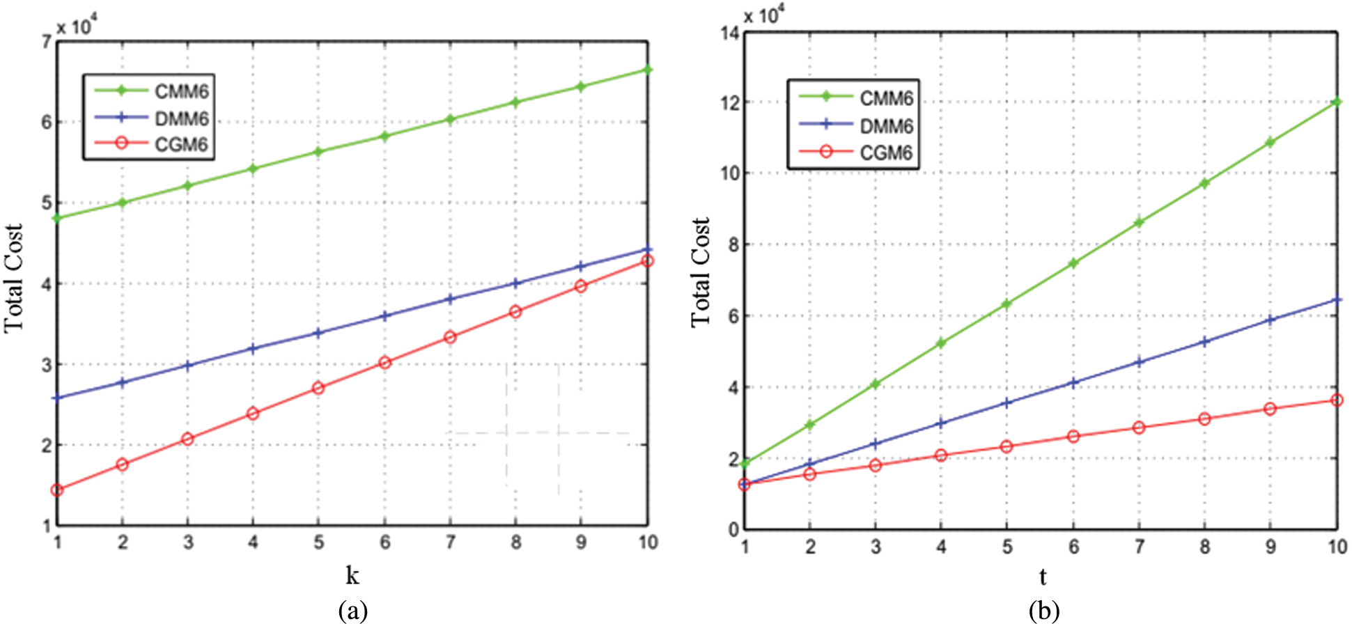
Figure 10: Effect of total cost on (a) wireless link transmission cost (k) and, (b) wired link transmission cost (t)
This paper proposes an efficient cluster-based group mobility scheme (CGM6) for resource constrained sensor nodes in 6LoWPAN. In CGM6, the functions of AAA server and LMA are integrated into a new entity called AMAG6. AMAG6 is responsible for binding and authentication process. It reduces the signaling cost through group authentication. Further, it reduces the number of control messages by acting as a cluster head. AMAG6 is also responsible for intra-cluster and inter-cluster communications of MN6s. The performance of CGM6 is evaluated through the extensive simulations. The simulation results show that CGM6 has reduced the handoff latency by 32%, registration delay by 11% and transmission cost by 37% compared to the state-of-the-art mobility management schemes.
1In this paper, we will use the terms sensor nodes and mobile nodes interchangeably.
Funding Statement: This research received no external funding.
Conflicts of Interest: The authors have no conflict of interest to declare.
1. A. Musaddiq, R. Ali, J. Choi, B. Kim and S. Kim, “Collision observation-based optimization of low-power and lossy IoT network using reinforcement learning,” Computers, Materials & Continua, vol. 67, no. 1, pp. 799–814, 2021. [Google Scholar]
2. N. Anjum, Z. Yang, H. Saki, M. Kiran and M. S. Bahaei, “Device-to-Device (D2D) communication as a bootstrapping system in a wireless cellular network,” IEEE Access, vol. 7, pp. 6661–6678, 2019. [Google Scholar]
3. F. Jameel, Z. Hamid, F. Jabeen, S. Zeadally and M. A. Javed, “A survey of Device-to-Device communications: Research issues and challenges,” IEEE Communications Surveys & Tutorials, vol. 20, no. 3, pp. 2133–2168, 2018. [Google Scholar]
4. D. Punia and R. Kumar, “Effect of mobility in IoT environment,” in 2nd Int. Conf. on Trends in Electronics and Informatics (ICOEITirunelveli, pp. 1534–1537, 2018. [Google Scholar]
5. T. Theodorou and L. Mamatas, “SD-MIoT: A software-defined networking solution for mobile Internet of Things,” IEEE Internet of Things Journal, vol. 8, no. 6, pp. 4604–4617, 2021. [Google Scholar]
6. B. Maha and R. Abderrezak, “A survey on mobility management protocols in wireless sensor networks based on 6LoWPAN technology,” Computer Communications, vol. 74, pp. 3–1515, 2016. [Google Scholar]
7. X. Wang, “Multicast for 6LoWPAN wireless sensor networks,” IEEE Sensors Journal, vol. 15, no. 5, pp. 3076–3083, 2015. [Google Scholar]
8. R. Beniwal, K. Nikolova and G. Iliev, “Performance analysis of MM-speed routing protocol implemented in 6LoWPAN environment,” in IEEE Int. Black Sea Conf. on Communications and Networking (BlackSeaComSochi, Russia, pp. 1–5, 2019. [Google Scholar]
9. R. Beniwal, K. Nikolova and G. Iliev, “MM-SPEED: Multipath multi-speed routing protocol in 6LoWPAN networks,” in Seventh Balkan Conf. on lighting (BalkanLightVarna, pp. 1–4, 2018. [Google Scholar]
10. T. Gomes, F. Salgado, S. Pinto, J. Cabral and A. Tavares, “A 6lowpan accelerator for internet of things endpoint devices,” IEEE Internet of Things Journal, vol. 5, no. 1, pp. 371–377, 2018. [Google Scholar]
11. B. R. Al-Kaseem, Y. Al-Dunainawi and H. S. Al-Raweshidy, “End-to-End delay enhancement in 6LoWPAN testbed using programmable network concepts,” IEEE Internet of Things Journal, vol. 6, no. 2, pp. 3070–3086, 2019. [Google Scholar]
12. X. Wang, “A Mobility frame for 6LoWPAN WSN,” IEEE Sensors Journal, vol. 16, no. 8, pp. 2755–2762, 2016. [Google Scholar]
13. V. Vasilev and M. Haka, “Enhanced simulation framework for realisation of mobility in 6LoWPAN wireless sensor networks,” in IEEE XXVIII Int. Scientific Conf. Electronics (ETSozopol, Bulgaria, pp. 1–4, 2019. [Google Scholar]
14. S. Gundavelli, K. Leung, V. Devarapalli, K. Chowdhury and B. Patil, “Proxy mobile IPv6,” IETF RFC 5213, 2008. [Google Scholar]
15. Y. Qiu and M. Ma, “A mutual authentication and key establishment scheme for M2M communication in 6LoWPAN networks,” IEEE Transactions on Industrial Informatic, vol. 12, no. 6, pp. 2074–2085, 2016. [Google Scholar]
16. S. Choi and S. Koh, “Use of proxy mobile IPv6 for mobility management in CoAP-based Internet-of-Things networks,” IEEE Communications Letters, vol. 20, no. 11, pp. 2284–2287, 2016. [Google Scholar]
17. N. Dutta, Z. Polkowski, C. Savulescu and S. Pathak, “An approach to signaling cost reduction in Proxy MIPv6 for mobility management,” in Int. Conf. on Advances in Computing, Communications, and Informatics, Jaipur, pp. 1654–1660, 2016. [Google Scholar]
18. Y. Qiu and M. Ma, “Secure group mobility support for 6LoWPAN networks,” IEEE Internet of Things Journal, vol. 5, no. 2, pp. 1131–1141, 2018. [Google Scholar]
19. F. Giust, L. Cominardi and C. J. Bernardos, “Distributed mobility management for future 5G networks: Overview and analysis of existing approaches,” IEEE Communications Magazine, vol. 53, no. 1, pp. 142–149, 2015. [Google Scholar]
20. S. Jeon, S. Figueiredo, R. L. Aguiar and H. Choo, “Distributed mobility management for the future mobile networks: A comprehensive analysis of key design options,” IEEE Access, vol. 5, pp. 11423–11436, 2017. [Google Scholar]
21. M. Balfaqih, M. Ismail, R. Nordin and Z. Balfaqih, “Handover performance evaluation of centralized and distributed network-based mobility management in vehicular urban environment,” in 9th IEEE-GCC Conf. and Exhibition, Manama, pp. 1–5, 2017. [Google Scholar]
22. M. Balfaqih, M. Ismail, R. Nordin and Z. Balfaqih, “802.21-Assisted distributed mobility management solution in vehicular networks,” IEEE Access, vol. 5, pp. 9518–9532, 2017. [Google Scholar]
23. T. Nguyen, C. Bonnet and J. Harri, “SDN-based distributed mobility management for 5G networks,” in IEEE Wireless Communications and Networking Conf., Doha, pp. 1–7, 2016. [Google Scholar]
24. Z. Yan, G. Geng, S. Zeadally and Y. Park, “Distributed all-IP mobility management architecture supported by the NDN overlay,” IEEE Access, vol. 5, pp. 243–251, 2017. [Google Scholar]
25. M. Gohar, J.-G. Choi, S.-J. Koh, K. Naseer and S. Jabbar, “Distributed mobility management in 6LoWPAN-based wireless sensor networks,” International Journal of Distributed Sensor Networks, vol. 11, no. 10, 2015. https://doi.org/10.1155/2015/620240. [Google Scholar]
26. J. Rubio, J. Murillo, J. Sánchez and J. Cancho, “SR-DMM: A SDN-based DMM solution for future mobile networks,” IEEE Latin America Transactions, vol. 17, no. 5, pp. 734–741, 2019. [Google Scholar]
27. M. Aman, S. Mahfooz, M. Zubair, K. Imran and S. Khusro, “Tunnel-free distributed mobility management (DMM) support protocol for future mobile networks,” Electronics, vol. 8, no. 12, pp. 1–19, 2019. [Google Scholar]
 | This work is licensed under a Creative Commons Attribution 4.0 International License, which permits unrestricted use, distribution, and reproduction in any medium, provided the original work is properly cited. |