DOI:10.32604/cmc.2021.017198
| Computers, Materials & Continua DOI:10.32604/cmc.2021.017198 | |
| Article |
Propagation Characterization and Analysis for 5G mmWave Through Field Experiments
1Centre for Cyber Security, Faculty of Information Science and Technology, Universiti Kebangsaan Malaysia (UKM), 43600, Bangi, Selangor, Malaysia
2Department of Electrical Engineering, Faculty of Engineering, University of Malaya, 50603, Kuala Lumpur, Malaysia
3Wireless Communication Centre, Faculty of Electrical Engineering, Universiti Teknologi Malaysia, 81310, Skudai, Johor, Malaysia
4Department of Computer Science and Communications Engineering, Faculty of Science and Engineering, Waseda University, Tokyo, 169-8050, Japan
*Corresponding Author: Quang Ngoc Nguyen. Email: quang.nguyen@fuji.waseda.jp
Received: 23 January 2021; Accepted: 25 February 2021
Abstract: The 5G network has been intensively investigated to realize the ongoing early deployment stage as an effort to match the exponential growth of the number of connected users and their increasing demands for high throughput, bandwidth with Quality of Service (QoS), and low latency. Given that most of the spectrums below 6 GHz are nearly used up, it is not feasible to employ the traditional spectrum, which is currently in use. Therefore, a promising and highly feasible effort to satisfy this insufficient frequency spectrum is to acquire new frequency bands for next-generation mobile communications. Toward this end, the primary effort has been focused on utilizing the millimeter-wave (mmWave) as the most promising candidate for the frequency spectrum. However, though the mmWave frequency band can fulfill the desired bandwidth requirements, it has been demonstrated to endure several issues like scattering, atmospheric absorption, fading, and especially penetration losses compared to the existing sub-6 GHz frequency band. Then, it is fundamental to optimize the mmWave band propagation channel to facilitate the practical 5G implementation for the network operators. Therefore, this study intends to investigate the outdoor channel characteristics of 26, 28, 36, and 38 GHz frequency bands for the communication infrastructure at the building to the ground floor in both Line of Sight (LOS) and Non-Line of Sight (NLOS) environments. The experimental campaign has studied the propagation path loss models such as Floating-Intercept (FI) and Close-In (CI) for the building to ground floor environment in LOS and NLOS scenarios. The findings obtained from the field experiments clearly show that the CI propagation model delivers much better performance in comparison with the FI model, thanks to its simple setup, accuracy, and precise function.
Keywords: 5G; mmWave; propagation channel; path loss; channel characterization; field experiment
With an explosive increase in high definition multimedia applications with high resolution, simultaneous communications of a huge number of devices with hundreds of new features, and massive data demands from the users for different content objects, the mobile data traffic will be boosted by 1000 times to meet the requirements [1]. The future mobile generation is also likely to overlook the drawbacks of the prior generation [2]. A typical approach is to adopt a Heterogeneous Network (HetNet), which facilitates seamless mobility, enhances end-user data rate, and reduces delays [3]. In today’s communication systems, the insufficient frequency band resources cannot fulfill the increasing demands of the next cellular networks [4]. Due to the growing tendency in the content size, data traffic, and user population, it is necessary to find efficient ways to go beyond today’s narrow and limited spectrum bandwidth while not compromising the user experience at the same time [5,6]. Presently, the most common issues regarding demands for excessive data rate with low energy and latency can be overcome if we keep up with the technical improvements to guarantee that the delay is less than 1 ms when obtaining a peak data rate of 100 Gbps [7]. For this goal, various possible approaches are presented in the literature, for examples; the use of higher frequency spectrum [8,9], Internet of Things (IoT) [10], Device-to-Device (D2D) [11,12], Four Single-Sideband [13], Wireless Sensor Networks (WSN) [11,14], HetNet [15]. Besides, there are several potential advancements in the currently used technologies addressing the next-generation network such as Coordinated Multipoint (CoMP) [16], Ethernet Passive Optical Network (EPON) [17], Mobile Ad-hoc Network (MANET) [18–20], Cognitive Radio [21,22], massive Multiple-Input and Multiple-Output (M-MIMO) [23] and relay assisted network [24], and so on. Moreover, several other techniques such as power optimizations [25,26], handover schemes [27], routing techniques [28,29], antenna designing [30,31], interference schemes [32,33], scheduling algorithms [34], data security management [35], and energy management schemes [36,37] have been utilized in the existing technology.
The 5G and high-frequency bands of the wireless communication networks are related to some minor contrary concepts [38]. To achieve the goal of enabling efficient communication systems toward 5G and beyond networks, utilizing higher frequency bands, commonly known as mmWave seems to be the only promising solution that is supremely capable of transmitting bulks of data compared to the current mobile network systems. The mmWave technology is a fundamental part of 5G that is to be utilized for seamless communications [39]. Specifically, in order to achieve the user’s demands, a high-frequency spectrum band of over 6 GHz is called mmWave that is known for delivering extremely large bandwidth [40].
The term mmWave indicates the high-frequency band ranging from 24 GHz to 100 GHz, which has a very short wavelength. It has been investigated in many fields and use-cases, including the overage probability optimization 5G cellular systems through flexible hybrid mmWave spectrum slicing-sharing access approach [41], designing of robust channel estimation schemes [42], the effect of beamforming on this technology [43], as well as the investigation of channel parameters and throughput estimates for mmWave networks [44]. However, some technical challenges are associated with the mmWave frequency high-band, and several studies on the mmWave spectrum are being performed via testing. Surprisingly, the mmWave wavelength (
The objective of any reliable transmission is to accomplish a steady and efficient communication link from Transmitter (Tx) to Receiver (Rx). Path loss is one of the important characteristics that can be affected by many factors, such as frequency of the signal, the distance between the source and destination, condition of the environment, and the effect of fading on the signal, weather condition [46]. Hence, many studies have analyzed numerous approaches in modeling different propagation path losses for several interferences and noise-limited settings to deal with the wireless network’s random nature [47].
In wireless communications, the channel characteristics depend largely on multiple factors, e.g., the type of air-interface design, the used radio spectrum, and the network architecture. The mmWave frequency band’s propagation behavior is unpredictable that needs to be countered by investigating the propagation channel model [48]. In this research, we design the field experiments with relevant propagation models to study and analyze the characterization of the high-frequency bands to keep the existing studies literature in mind. Specifically, the study provides detailed field experiments of mmWave frequency bands, then investigates extensive results to reveal the signal propagation and attenuation in a unique propagation environment for both LOS and NLOS scenarios. Additionally, this yields a comparison between two relevant propagation models to verify the efficiency and feasibility of mmWave with high-band for practical deployment of B5G, based on the actual experimental data. To the best of our knowledge, it is believed that this kind of environment with these frequency ranges has not been performed previously. Moreover, the outcomes shown in the study are positive, suitable, and useful to assess and facilitate the practical implementation of the future mobile network.
The remainder of this article is organized as follows: Section 2 describes the recent related researches in literature. The hardware equipment and the experimental field setup are described in Section 3. The propagation models are described in Section 4. The key results and discussion are presented in Section 5. Finally, we conclude the paper in Section 6.
The mmWave frequency band’s uncertain characteristic emphasizes the need to investigate different relevant propagation models to predict path loss to enable an efficient implementation of the methodology in practice. In [49], the authors suggested that the E-band spectrum could be a better choice for upcoming cellular systems if being applied with beam-steering and beam combining methods for the urban micro-cell environments. The results also revealed that the directional antennas help make the mmWave channel feasible enough to reach the desired goal of implementing a 5G network system. Moreover, the data has been measured at 28 and 73 GHz for omnidirectional propagation models. However, the path losses turn out to be much higher in the case of omnidirectional models for mmWave bands as compared to the UHF and microwave bands. In [50], the mmWave frequency bands, 28 and 73 GHz, are studied for the Alpha Beta Gama (ABG) model to develop an urban micro-cell LOS scenario. The evaluations have been derived in terms of various fairness, throughput, and efficiency. The results show the improvement of 95 and 180% in the spectrum efficiency for 28 and 73 GHz, respectively.
In [51], the path loss characteristics at 28 GHz have been found out for signal processing methods using 3D ray-tracing software. It also suggested that the shadowing factor can be considered in an indoor scenario to generate better-simulated results. In another study [52], the 28 and 38 GHz mmWave frequency bands work on two propagation models named CI (Close-In) and ABG by using measurement data. The outcome shows better results for the CI model compared to the ABG model and can be implemented for the 5G network. Furthermore, the 38 GHz band turned out to be better results for spectral efficiency and average cell throughput as compared to 28 GHz. Theodore Rappaport led the Wireless team of the New York University (NYU), who studied the penetration losses and reflection at 28 GHz for the glass building in New York City [53]. The results show that due to the glass material of buildings, it acts as an excellent reflector, which provides 89% of the transmitted signal compared to a directly transmitted signal.
Another experimental work has been performed in an indoor environment for 28 GHz [54]. The Tx and Rx are placed at both LOS and NLOS scenarios including the case where they are placed at two different floors. The experiment was performed by using the CI and FI (Floating-Intercept) propagation models. Specifically, the outcomes show that both CI and FI models gave a good match with empirical path loss results; however, the CI model’s results are very close to the free space path loss models. Another study investigated at 28 and 73 GHz frequency bands using CI and FI path loss models based on LOS and NLOS omnidirectional signal propagation [55]. It provides various results such as interference, outage, and coverage, then motivates us to conduct this field-experiment study. The results indicate that the site-specific environmental information may be applied to yield the probabilistic weighting function for choosing to give us between LOS and conditions.
Similarly, the performance analysis is done by estimating measured and simulated results to validate the SBR/IM (Shooting and bouncing ray tracing/image) method [56]. Various channel properties, such as path loss values and channel capacity, are discussed for experimental and simulated results. Also, the Path Loss Exponent (PLE) has been extracted from the measurement results. By making use of a Three-Dimensional (3D) ray-tracing method, the propagation models are studied in [57]. A comparison has been made between simulated and measured results to verify the 3D ray-tracing method’s suitability for both LOS and NLOS scenarios. However, the shadowing factor showed significant differences in the NLOS scenario.
In order to estimate the behavior of the transmitted signal, the radio signal is propagated from Tx to Rx in a wireless channel. Therefore, in this experiment, the mmWave signals having the frequency of 26, 28, 36, 38 GHz are transmitted through a wireless channel by using the directional (horn) antenna. The maximum or bore-sight free space gain of the antenna has been calculated by using the Brewster angle relationship. The synthesized Signal Generator (MG369xC) has been used to transmitted the propagation signal from the Tx side, whereas the Anritsu MS2720T handheld spectrum analyzer is used at the Rx side, which utilizes a circular (Omni) antenna to capture the received signal. The set bandwidth of the transmitted signal is 100 MHz with
Table 1: Channel sounder specification
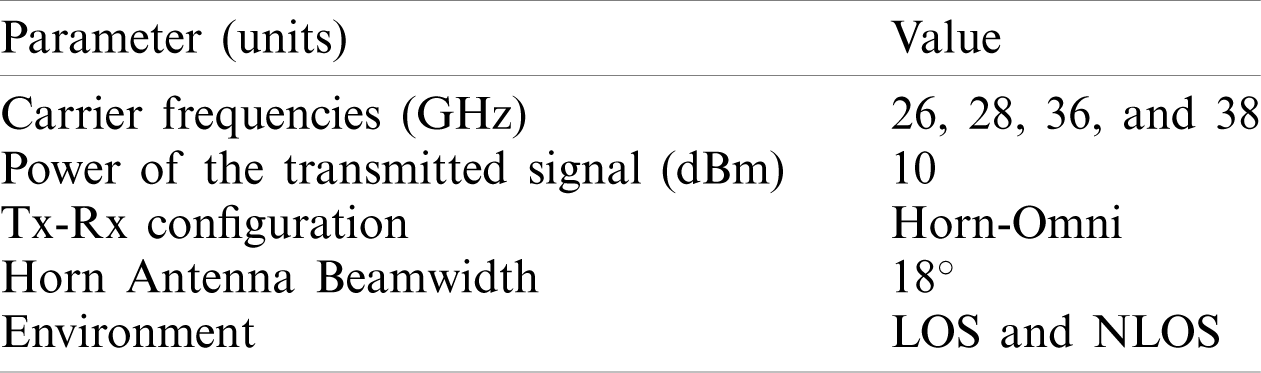
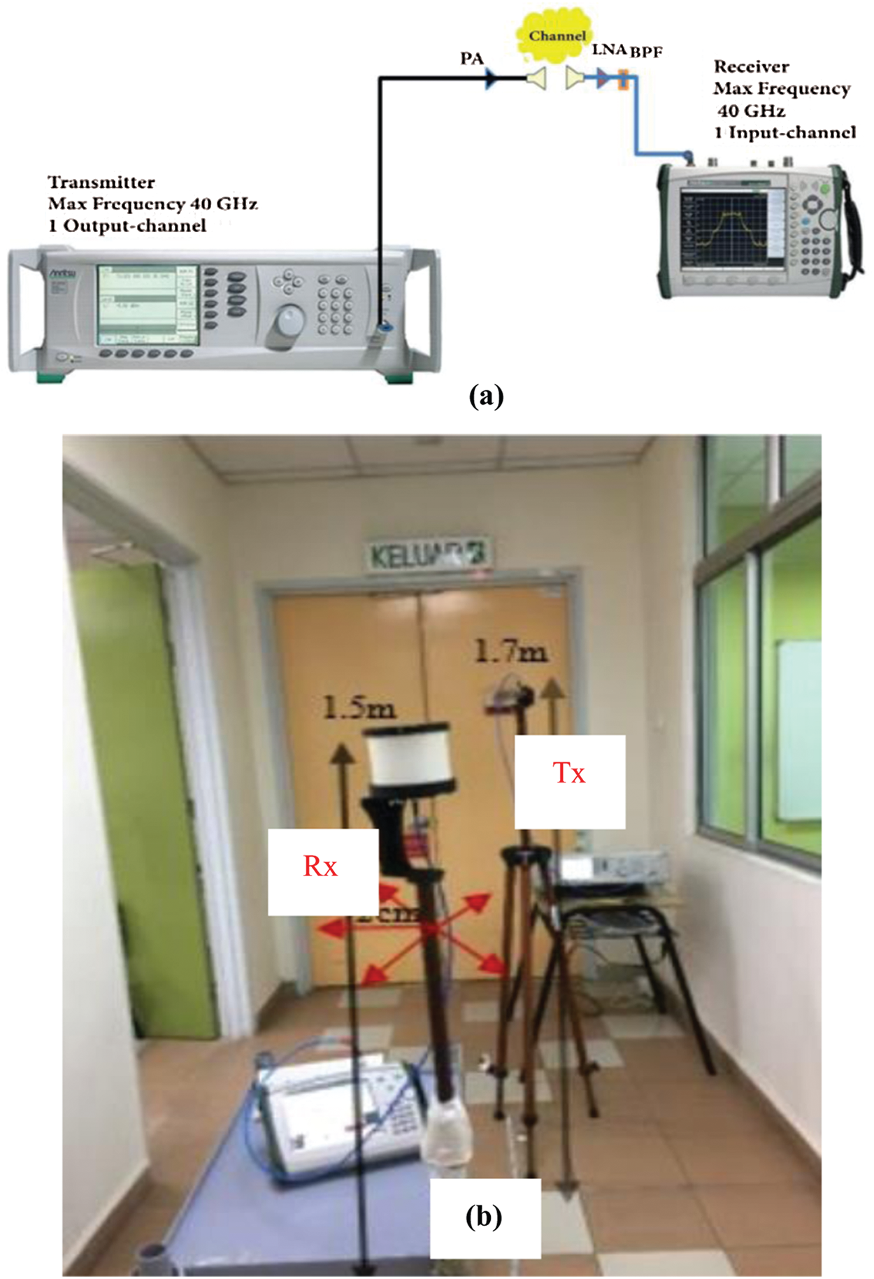
Figure 1: (a) Hardware equipment, (b) experimental setup
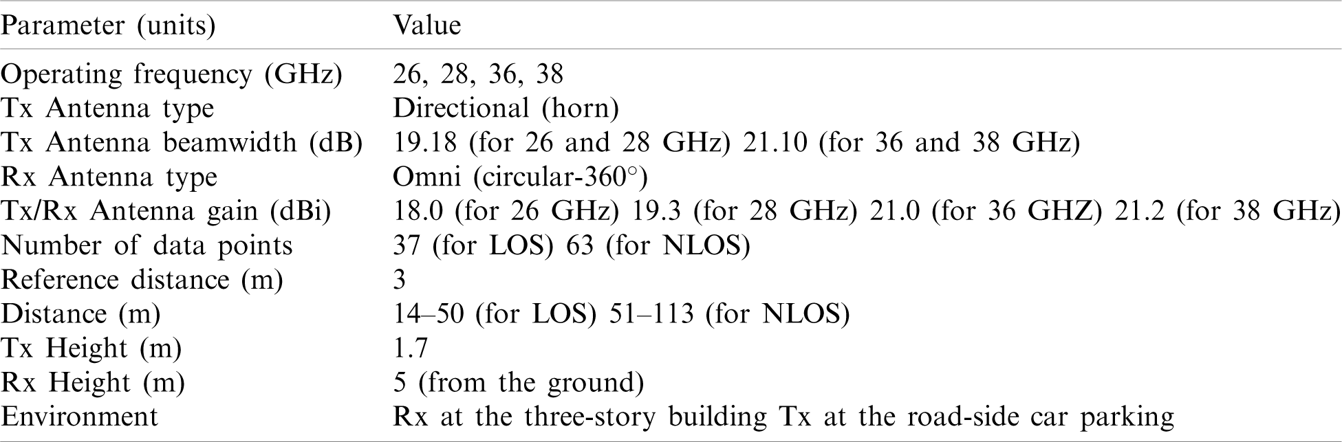
The experiment was carried out inside a KL (Kuala Lumpur) campus of Universiti Teknologi Malaysia (UTM). As shown in Fig. 2, the Tx is placed in the hallway at the 1st level of a 3-level library office at a fixed position in the corridor, whereas the Rx is on the ground floor of the parking road. The heights of a Tx and Rx are 5 and 1.7 m above the ground level, respectively. The Rx is moved 113 m at a step unit of 1 m. The zero points resultant space is 14 m between Tx and Rx. The road’s surrounding is an open green field to the south, while the cars were parked on the road’s northside. Besides, there are several cars parked on the road, the sides of the pedestrian walkway have many palm trees, causing a half blockage (reflection/refraction effect) in between the Tx and Rx. The library building consists of a structure with non-tinted glass and a painted hardboard frame. The resulting distance for LOS propagation is from 14 m to 50 m, and NLOS propagation ranges from 51 m to 113 m. The area is static throughout the experiments (no human movement is observed during the experiment). Tab. 2 summarizes the experiment specification with key parameters and values of the performed experiments.
Figure 2: WCC-building and car parking environment
Table 2: Summary of experimental specification
The propagation path loss models can help us perform a detailed examination of the wireless channel’s propagation attributes. They have utilized the signal frequency and the physical distance between source to destination and to find out the reduction in the transmitted signal. This study focuses on Free-Space Path Loss (FSPL) propagation models, such as CI and FI models, to serve the purpose [58].
The CI propagation path loss model is an intrinsic frequency-dependent path loss model. It is focusing on
here,
The
The
here, the standard deviation
The collected path loss data points are represented by N, and the n and minimum
The FI propagation model is used to find the best lowest error fit value by using floating intercept (
The
here, the standard deviation
The collected path loss data points are represented by N, and the Minimum Mean Squared Error (MMSE) method is used to decrease the standard deviation (
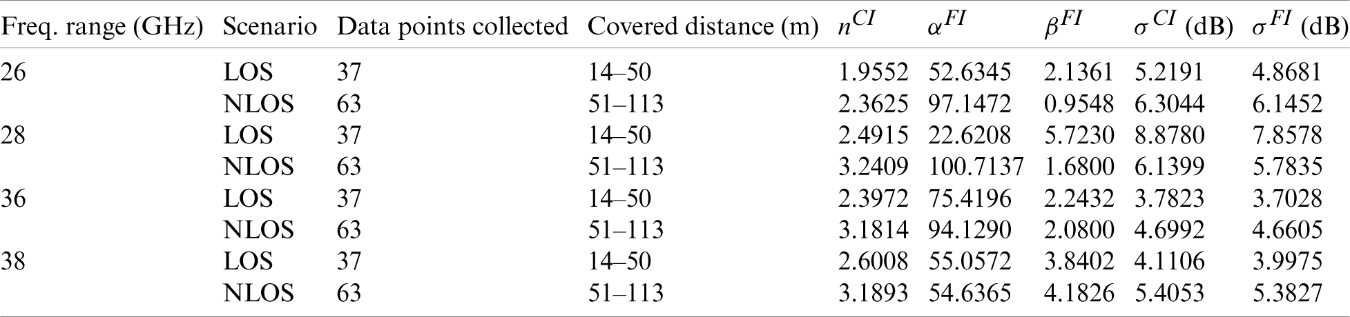
In this experiment, the four popular frequency high-bands 26, 28, 36, and 38 GHz have been intensely studied and investigated to reveal results and draw a comparison between LOS and NLOS environments with different propagation models. For the LOS environment, the number of data points is 37 for a distance range of around 14–50 m. For the NLOS environment, the number of data points used is 63, and the distance range is increased to 51–113 m compared to the LOS environment. However, the reference distance (3 m) is the same in both environments. The PLE and shadowing factor are the two crucial parameters in the CI model that help to analyze the important results for all four frequencies. From these results, we can see how signal propagation is performed when the Tx-Rx separation is varied. In the end, the comparison is drawn among different frequencies, environments, and channel conditions.
5.1 Results for CI Path Loss Model
The CI path loss model results are shown in Fig. 3 regarding the experimental specification described in Tab. 2. The overall pattern shows that the path loss values escalate as the separation from Tx to Rx has increased. Fig. 3a shows the 26 GHz frequency band results, where the LOS case performs better than NLOS in this scenario. The PLE (nCI) values for the 26 GHz are turned out to be at 1.95523 and 2.3625 for LOS and NLOS scenarios, respectively. However, the shadowing factors appear to be 5.2191 dB and 6.3044 dB for LOS and NLOS cases.
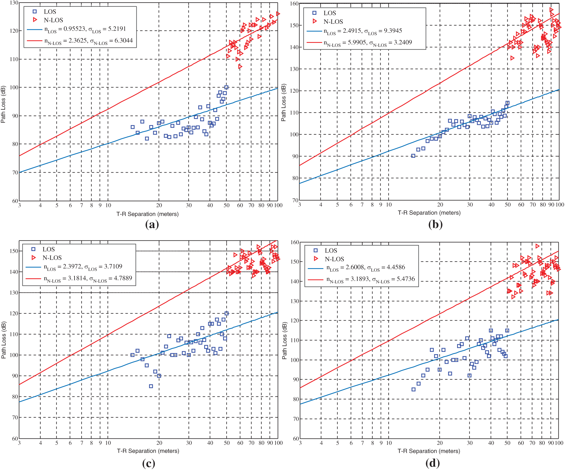
Figure 3: CI path loss model results for (a) 26 GHz, (b) 28 GHz, (c) 36 GHz, (d) 38 GHz
Similarly, in the case of 28 GHz, the path loss keeps the same trend and increases gradually with the effect of Tx-Rx separation distance, as shown in Fig. 3b. The nCI values are 2.4915 and 3.2409 for both LOS and NLOS case studies, respectively. However, the nCI values are slightly higher than the values observed for 26 GHz. Moreover, the shadowing factor is 9.3945 dB in the LOS environment, which is also higher than the measured LOS shadowing factor of 26 GHz. Nevertheless, the shadowing factor slightly goes down to 5.9905 dB in the case of the NLOS environment.
While experimenting with 36 GHz, the LOS and NLOS case studies have shown the nCI values appear to be 2.3972 and 3.1814, respectively, as shown in Fig. 3c. It is clear that the signal deteriorates more in the NLOS region as compared to the LOS region. Moreover, the shadowing factors of 3.7109 dB for the LOS case and 4.7889 dB for the NLOS case. As understood from the previous analysis, there is a significant drop in value which can be observed if compared to 28 GHz. In short, the signal performance in the NLOS environment is visibly lower as compared to the LOS environment.
Likewise, for 38 GHz with the CI path loss model, Fig. 3d shows that the LOS and NLOS scenarios have the nCI values of 2.6008 and 3.1893, respectively. Similarly, we have the shadowing factors of 4.4586 dB for the LOS scenario and 5.4736 dB for NLOS scenarios. It is proved that the increment in the separation between Tx and Rx, causing higher attenuation loss; therefore, the noticeable growth in the path loss values is observed.
5.2 Results for FI Path Loss Model
The FI path loss model results have been plotted for 26, 28, 36, and 38 GHz to show the propagation effect, as shown in Fig. 4. For the 26 GHz, the signal deteriorates aggressively in the NLOS region, as shown in Fig. 4a. In the LOS scenario, the
For the results of 36 GHz, Fig. 4c shows the LOS scenario for the FI model, where the
5.3 Evaluation Results and Discussion
In Tab. 3, the summary of the comparison of various frequencies has been drawn based on multiple environments, including PLE,
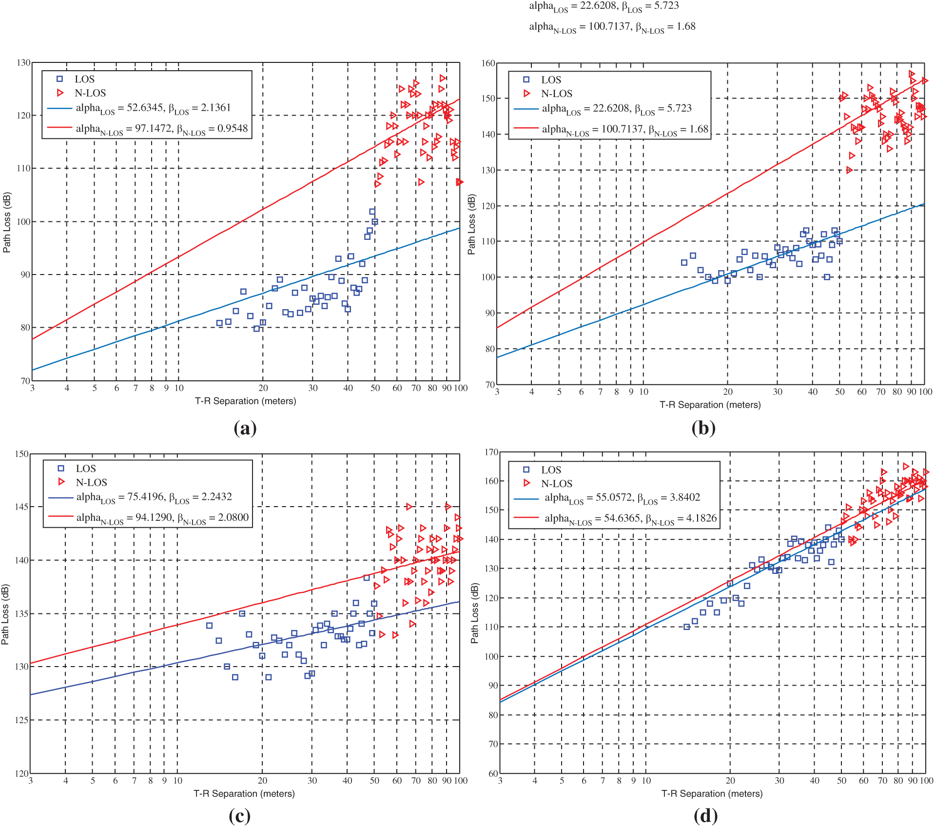
Figure 4: FI path loss model results for (a) 26 GHz, (b) 28 GHz, (c) 36 GHz, (d) 38 GHz
The results of the FI model are also summarized in Tab. 3. In the LOS case study, the FI (
Table 3: Summary of CI and FI path loss models results
The next-generation network is going to use the higher frequency spectrum commonly known as the mmWave frequency band. Along with many advantages, it also brings several challenges such as signal attenuation due to atmospheric concentration, penetration losses, scattering, and fading. These issues can be mitigated if we are able to understand the behavior of the transmission channel before transmitting the signal. In this regard, this experimental campaign has studied the relevant propagation path loss models, namely CI and FI for the communication infrastructure at the building to ground floor environment at 26, 28, 36, and 38 GHz in LOS and NLOS scenarios. The results have been drawn to show large-scale metrics such as path-loss and shadowing factors for both LOS and NLOS scenarios. The experimental findings prove that the CI model delivers better accuracy for the model, especially in the case of the 26 GHz with very small values of PLE in both the NLOS and LOS environments. It also demonstrates that the CI model is very simple and provides very steady performance results for the whole experiment with all the tested frequencies. The evaluation results via the field experiment then have proved that the CI model could achieve better performance results on similar scenarios and frequencies for the 5G mmWave signal propagation. For further potential work, various other high-frequency ranges such as sub-6 GHz and above 100 GHz can be estimated and compared with tested frequency bands. Additionally, some different potential propagation path loss models like CI with frequency weighted (CIF) can also be tested in order to verify for the realization of higher quality signal transmission with the highly efficient propagation model for 5G and beyond networks.
Acknowledgement: The authors would also like to thank the Universiti Teknologi Malaysia (UTM) Wireless Communication Centre (WCC) for their support in setting up and conducting the experiment.
Data Availability: The data used to support the findings of this study are available from the corresponding author upon request.
Funding Statement: This study is supported by the School of Fundamental Science and Engineering, Faculty of Science and Engineering, Waseda University, Japan. The research was also supported under the Dana Impak Perdana (DIP) Grant Scheme DIP-2018-040 and FRGS/1/2018/TK04/UKM/02/17.
Conflicts of Interest: The authors declare that they have no conflicts of interest to report regarding the present study.
1. A. R. Prasad, S. Arumugam, B. Sheeba and A. Zugenmaier, “3GPP 5G security,” Journal of ICT Standardization, vol. 6, no. 1, pp. 137–158, 2018. [Google Scholar]
2. S. Han, J. W. Choi and J. Kim, “Numerical approximation of millimeter-wave frequency sharing between cellular systems and fixed service systems,” Journal of Communications and Networks, vol. 22, no. 1, pp. 37–45, 2020. [Google Scholar]
3. I. Shgluof, M. Ismail and R. Nordin, “An enhanced system information acquisition scheme for CSG femtocells in 3GPP LTE/LTE-A systems,” Wireless Personal Communications, vol. 96, no. 3, pp. 3995–4011, 2017. [Google Scholar]
4. F. Qamar, T. Abbas, M. N. Hindia, K. B. Dimyati, K. A. B. Noordin et al., “Characterization of MIMO propagation channel at 15 GHz for the 5G spectrum,” in Proc. 2017 IEEE 13th Malaysia Int. Conf. on Communications, Johor, Malaysia, pp. 265–270, 2017. [Google Scholar]
5. S. Weber, J. G. Andrews and N. Jindal, “An overview of the transmission capacity of wireless networks,” IEEE Transactions on Communications, vol. 58, no. 12, pp. 3593–3604, 2010. [Google Scholar]
6. S. Talwar, D. Choudhury, K. Dimou, E. Aryafar, B. Bangerter et al., “Enabling technologies and architectures for 5G wireless,” in Proc. 2014 IEEE MTT-S Int. Microwave Symp. (IMS-2014Tampa, Florida, USA, pp. 1–4, 2014. [Google Scholar]
7. F. Qamar, K. Dimyati, M. N. Hindia, K. A. Noordin and I. S. Amiri, “A stochastically geometrical poisson point process approach for the future 5G D2D enabled cooperative cellular network,” IEEE Access, vol. 7, pp. 60465–60485, 2019. [Google Scholar]
8. T. S. Rappaport, S. Sun, R. Mayzus, H. Zhao, Y. Azar et al., “Millimeter wave mobile communications for 5G cellular: It will work!,” IEEE Access, vol. 1, no. 1, pp. 335–349, 2013. [Google Scholar]
9. P. J. Okoth, Q. N. Nguyen, D. R. Dhakal, D. Nozaki, Y. Yamada et al., “An efficient codebook-based beam training technique for millimeter-wave communication systems,” in Proc. 2018 IEEE Asia-Pacific Microwave Conf. (APMC-2018Kyoto, Japan, pp. 666–668, 2018. [Online]. Available: https://ieeexplore.ieee.org/iel7/8599618/8617121/08617193.pdf?casa_token=cTPMfWw2VQAAAAAA:2OgFj-QuIaMNbhF20gOr421E7ZmexxWVN_k1IedBnH6HlOo9SGouk5XhoQUJva_vactDsDZ_wj2TFg. [Google Scholar]
10. R. Hassan, F. Qamar, M. K. Hasan, A. H. M. Aman and A. S. Ahmed, “Internet of things and its applications: A comprehensive survey,” Symmetry, vol. 12, no. 10, pp. 1674, 2020. [Google Scholar]
11. Q. N. Nguyen, M. Arifuzzaman, K. Yu and T. Sato, “A context-aware green information-centric networking model for future wireless communications,” IEEE Access, vol. 6, pp. 22804–22816, 2018. [Google Scholar]
12. A. R. Javed, R. Abid, B. Aslam, H. A. Khalid, M. Z. Khan et al., “Green5G: Enhancing capacity and coverage in device-to-device communication,” Computers, Materials & Continua, vol. 67, no. 2, pp. 1933–1950, 2021. [Google Scholar]
13. M. M. Alhasani, Q. N. Nguyen, G. I. Ohta and T. Sato, “A novel four single-sideband M-QAM modulation scheme using a shadow equalizer for MIMO system toward 5G communications,” Sensors, vol. 19, no. 8, pp. 1944, 2019. [Google Scholar]
14. D. P. Dahnil and R. Hassan, “Wireless sensor networks: A framework for community and educational gardens,” Advanced Science Letters, vol. 24, no. 2, pp. 1153–1157, 2018. [Google Scholar]
15. A. Gachhadar, F. Qamar, D. S. Dong, M. B. Majed, E. Hanafi et al., “Traffic offloading in 5G heterogeneous networks using rank based network selection,” Journal of Engineering Science & Technology Review, vol. 12, no. 2, pp. 9–16, 2019. [Online]. Available: http://www.jestr.org/downloads/Volume12Issue2/fulltext21222019.pdf. [Google Scholar]
16. F. Qamar, K. B. Dimyati, M. N. Hindia, K. A. B. Noordin and A. M. Al-Samman, “A comprehensive review on coordinated multi-point operation for LTE-A,” Computer Networks, vol. 123, pp. 19–37, 2017. [Google Scholar]
17. D. Udeshi and F. Qamar, “Quality analysis of EPON network for uplink and downlink design,” Asian Journal of Engineering, Sciences & Technology, vol. 4, no. 2, pp. 78–83, 2014. [Online]. Available: http://ajest.iqra.edu.pk/journalissue.php?id=tXY8DI8v2oY%3D. [Google Scholar]
18. V. Tilwari, M. N. Hindia, K. Dimyati, F. Qamar, A. Talip et al., “Contention window and residual battery aware multipath routing schemes in mobile ad-hoc networks,” International Journal of Technology, vol. 10, no. 7, pp. 1376–1384, 2019. [Google Scholar]
19. T. A. N. Abdali, R. Hassan, R. C. Muniyandi, A. H. Mohd Aman, Q. N. Nguyen et al., “Optimized particle swarm optimization algorithm for the realization of an enhanced energy-aware location-aided routing protocol in MANET,” Information—An International Interdisciplinary Journal, vol. 11, no. 11, pp. 529, 2020. [Google Scholar]
20. T. Abbas, F. Qamar, M. N. Hindia, R. Hassan, I. Ahmed et al., “Performance analysis of ad hoc on-demand distance vector routing protocol for MANET,” in Proc. IEEE, 2020 Student Conf. on Research and Development, Johor, Malaysia, pp. 194–199, 2020. [Google Scholar]
21. M. N. Hindia, F. Qamar, H. Ojukwu, K. Dimyati, A. M. Al-Samman et al., “On platform to enable the cognitive radio over 5G networks,” Wireless Personal Communications, vol. 2, no. 1, pp. 1–22, 2020. [Online]. Available: https://www.springerprofessional.de/en/on-platform-to-enable-the-cognitive-radio-over-5g-networks/17880188. [Google Scholar]
22. F. Qamar, M. U. A. Siddiqui, M. Hindia, R. Hassan and Q. N. Nguyen, “Issues, challenges, and research trends in spectrum management: A comprehensive overview and new vision for designing 6G networks,” Electronics, vol. 9, no. 9, pp. 1416, 2020. [Google Scholar]
23. T. E. Bogale and L. B. Le, “Massive MIMO and mmWave for 5G wireless HetNet: Potential benefits and challenges,” IEEE Vehicular Technology Magazine, vol. 11, no. 1, pp. 64–75, 2016. [Google Scholar]
24. M. N. Hindia, F. Qamar, T. A. Rahman and I. S. Amiri, “A stochastic geometrical approach for full-duplex MIMO relaying model of high-density network,” Ad Hoc Networks, vol. 74, no. 2, pp. 34–46, 2018. [Google Scholar]
25. A. Gachhadar, M. N. Hindia, F. Qamar, M. H. S. Siddiqui, K. A. Noordin et al., “Modified genetic algorithm based power allocation scheme for amplify-and-forward cooperative relay network,” Computers & Electrical Engineering, vol. 69, no. 2, pp. 628–641, 2018. [Google Scholar]
26. K. A. B. Noordin, M. N. Hindia, F. Qamar and K. Dimyati, “Power allocation scheme using PSO for amplify and forward cooperative relaying network,” in Proc. Springer Science and Information (SAI) Conf., London, United Kingdom, pp. 636–647, 2018. [Google Scholar]
27. R. Hassan, A. H. M. Aman and L. A. Latiff, “Framework for handover process using visible light communications in 5G,” in Proc. 2019 IEEE Symp. on Future Telecommunication Technologies, Kuala Lumpur, Malaysia, pp. 1–4, 2019. [Google Scholar]
28. S. Malathy, V. Porkodi, A. Sampathkumar, M. N. Hindia, K. Dimyati et al., “An optimal network coding based backpressure routing approach for massive IoT network,” Wireless Networks, vol. 26, no. 5, pp. 1–18, 2020. [Google Scholar]
29. I. Amiri, D. S. Dong, Y. M. Pokhrel, A. Gachhadar, R. K. Maharjan et al., “Resource tuned optimal random network coding for single hop multicast future 5G networks,” International Journal of Electronics and Telecommunications, vol. 65, no. 3, pp. 463–469, 2019. [Google Scholar]
30. D. A. Sehrai, F. Muhammad, S. H. Kiani, Z. H. Abbas, M. Tufail et al., “Gain-enhanced metamaterial based antenna for 5G communication standards,” Computers, Materials & Continua, vol. 64, no. 3, pp. 1587–1599, 2020. [Google Scholar]
31. A. Haider, T. Khan, M. Rahman, B. M. Lee and H. S. Kim, “Quintuple band antenna for wireless applications with small form factor,” Computers, Materials & Continua, vol. 66, no. 3, pp. 2241–2251, 2021. [Google Scholar]
32. F. Qamar, M. N. Hindia, K. Dimyati, K. A. Noordin and I. S. Amiri, “Interference management issues for the future 5G network: A review,” Telecommunication Systems, vol. 71, no. 4, pp. 627–643, 2019. [Google Scholar]
33. M. N. Hindia, F. Qamar, T. Abbas, K. Dimyati, M. S. Abu Talip et al., “Interference cancelation for high-density fifth-generation relaying network using stochastic geometrical approach,” International Journal of Distributed Sensor Networks, vol. 15, no. 7, pp. 1550147719855879, 2019. [Google Scholar]
34. M. N. Hindia, F. Qamar, M. B. Majed, T. A. Rahman and I. S. Amiri, “Enabling remote-control for the power sub-stations over LTE-A networks,” Telecommunication Systems, vol. 70, no. 1, pp. 1–17, 2018. [Google Scholar]
35. Z. Saizan and D. Singh, “Cyber security awareness among social media users: Case study in German-Malaysian Institute (GMI),” Asia-Pacific Journal of Information Technology & Multimedia, vol. 7, no. 2, pp. 111–127, 2018. [Google Scholar]
36. L. Nguyen, “Resource management for wireless communications: An energy efficiency approach,” Ph.D. dissertation, Queen’s University, Belfast, United Kingdom, 2018. [Google Scholar]
37. Q. N. Nguyen, K. Yu, T. Sato and M. Arifuzzaman, “A game-theoretical green networking approach for information-centric networks,” in Proc. 2017 IEEE Conf. on Standards for Communications and Networking, Helsinki, Finland, pp. 132–137, 2017. [Google Scholar]
38. F. Qamar, M. N. Hindia, T. A. Rahman, R. Hassan and S. Saleem, “Outdoor propagation channel investigation at 26 GHz for 5G mmWave communication,” in Proc. IEEE, 2020 Student Conf. on Research and Development, Johor, Malaysia, pp. 189–193, 2020. [Google Scholar]
39. F. Qamar, M. H. S. Siddiqui, M. N. Hindia, K. Dimyati, T. A. Rahman et al., “Propagation channel measurement at 38 GHz for 5G mm-wave communication network,” in Proc. 2018 IEEE Student Conf. on Research and Development, Selangor, Malaysia, pp. 1–6, 2018. [Google Scholar]
40. F. Qamar, M. Hindia, K. Dimyati, K. A. Noordin, M. B. Majed et al., “Investigation of future 5G-IoT millimeter-wave network performance at 38 GHz for urban microcell outdoor environment,” Electronics, vol. 8, no. 5, pp. 485, 2019. [Google Scholar]
41. M. L. Attiah, A. Isa, Z. Zakaria, M. Ismail, R. Nordin et al., “Coverage probability optimization utilizing flexible hybrid mmWave spectrum slicing-sharing access strategy for 5G cellular systems,” Journal of Telecommunication, Electronic and Computer Engineering, vol. 10, no. 2, pp. 91–98, 2018. [Google Scholar]
42. I. Khan, J. J. Rodrigues, J. Al-Muhtadi, M. I. Khattak, Y. Khan et al., “A robust channel estimation scheme for 5G massive MIMO systems,” Wireless Communications and Mobile Computing, vol. 2019, pp. 1–9, 2019. [Google Scholar]
43. S. Y. Nusenu and E. Asare, “Butler matrix frequency diverse retrodirective array beamforming: An energy-efficient technique for mmWave networks,” Wireless Communications and Mobile Computing, vol. 2020, no. 6, pp. 1–12, 2020. [Google Scholar]
44. N. F. Abdullah, D. Berraki, A. Ameen, S. Armour, A. Doufexi et al., “Channel parameters and throughput predictions for mmWave and LTE-A networks in urban environments,” in Proc. 2015 IEEE 81st Vehicular Technology Conf. (VTC SpringGlasgow, United Kingdom, pp. 1–5, 2015. [Google Scholar]
45. F. Qamar, M. N. Hindia, T. Abbas, K. B. Dimyati and I. S. Amiri, “Investigation of QoS performance evaluation over 5G network for indoor environment at millimeter wave bands,” International Journal of Electronics and Telecommunications, vol. 65, no. 1, pp. 95–101, 2019. [Google Scholar]
46. K. Haneda, J. Zhang, L. Tan, G. Liu, Y. Zheng et al., “5G 3GPP-like channel models for outdoor urban microcellular and macrocellular environments,” in Proc. 2016 IEEE 83rd Vehicular Technology Conf. (VTC SpringNanjing, China, pp. 1–7, 2016. [Google Scholar]
47. T. S. Rappaport, Y. Xing, G. R. MacCartney, A. F. Molisch, E. Mellios et al., “Overview of millimeter wave communications for fifth-generation (5G) wireless networks: With a focus on propagation models,” IEEE Transactions on Antennas and Propagation, vol. 65, no. 12, pp. 6213–6230, 2017. [Google Scholar]
48. T. Hong, J. Yao, C. Liu and F. Qi, “Mmwave measurement of RF reflectors for 5G green communications,” Wireless Communications and Mobile Computing, vol. 2018, pp. 1–11, 2018. [Google Scholar]
49. G. R. MacCartney and T. S. Rappaport, “73 GHz millimeter wave propagation measurements for outdoor urban mobile and backhaul communications in New York,” in Proc. 2014 IEEE Int. Conf. on Communications, Sydney, Australia, pp. 4862–4867, 2014. [Google Scholar]
50. T. Abbas, F. Qamar, I. Ahmed, K. Dimyati and M. B. Majed, “Propagation channel characterization for 28 and 73 GHz millimeter-wave 5G frequency band,” in Proc. 2017 IEEE 15th Student Conf. on Research and Development, Putrajaya, Malaysia, pp. 297–302, 2017. [Google Scholar]
51. F. Hossain, T. K. Geok, T. A. Rahman, M. N. Hindia, K. Dimyati et al., “An efficient 3-D ray tracing method: Prediction of indoor radio propagation at 28 GHz in 5G network,” Electronics, vol. 8, no. 3, pp. 286, 2019. [Google Scholar]
52. F. Qamar, M. H. S. Siddiqui, K. Dimyati, K. A. B. Noordin and M. B. Majed, “Channel characterization of 28 and 38 GHz mm-wave frequency band spectrum for the future 5G network,” in Proc. 2017 IEEE 15th Student Conf. on Research and Development, Putrajaya, Malaysia, pp. 291–296, 2017. [Google Scholar]
53. H. Zhao, R. Mayzus, S. Sun, M. Samimi, J. K. Schulz et al., “28 GHz millimeter wave cellular communication measurements for reflection and penetration loss in and around buildings in New York city,” in Proc. 2013 IEEE Int. Conf. on Communications (ICCBudapest, Hungary, pp. 5163–5167, 2013. [Google Scholar]
54. F. Erden, O. Ozdemir and I. Guvenc, “28 GHz mmWave channel measurements and modeling in a library environment,” in Proc. IEEE, 2020 Radio and Wireless Symp., Texas USA, pp. 52–55, 2020. [Google Scholar]
55. M. K. Samimi, T. S. Rappaport and G. R. MacCartney, “Probabilistic omnidirectional path loss models for millimeter-wave outdoor communications,” IEEE Wireless Communications Letters, vol. 4, no. 4, pp. 357–360, 2015. [Google Scholar]
56. S. Li, Y. Liu, L. Lin, X. Sun, S. Yang et al., “Millimeter-wave channel simulation and statistical channel model in the cross-corridor environment at 28 GHz for 5G wireless system,” in Proc. 2018 IEEE Int. Conf. on Microwave and Millimeter Wave Technology, Chengdu, China, pp. 1–3, 2018. [Google Scholar]
57. J. H. Lee, J. S. Choi, J. Y. Lee and S. C. Kim, “28 GHz millimeter-wave channel models in urban microcell environment using three-dimensional ray tracing,” IEEE Antennas and Wireless Propagation Letters, vol. 17, no. 3, pp. 426–429, 2018. [Google Scholar]
58. Q. Faizan, “Enhancing QOS performance of the 5G network by characterizing mm-wave channel and optimizing interference cancellation scheme,” Ph.D. dissertation, University of Malaya, Malaysia, 2019. [Google Scholar]
59. S. Sun, T. S. Rappaport, T. A. Thomas, A. Ghosh, H. C. Nguyen et al., “Investigation of prediction accuracy, sensitivity, and parameter stability of large-scale propagation path loss models for 5G wireless communications,” IEEE Transactions on Vehicular Technology, vol. 65, no. 5, pp. 2843–2860, 2016. [Google Scholar]
60. T. S. Rappaport, G. R. MacCartney, M. K. Samimi and S. Sun, “Wideband millimeter-wave propagation measurements and channel models for future wireless communication system design,” IEEE Transactions on Communications, vol. 63, no. 9, pp. 3029–3056, 2015. [Google Scholar]
61. S. Sun, G. R. MacCartney and T. S. Rappaport, “Millimeter-wave distance-dependent large-scale propagation measurements and path loss models for outdoor and indoor 5G systems,” in Proc. 2016 IEEE 10th European Conference on Antennas and Propagation, Davos, Switzerland, pp. 1–5, 2016. [Google Scholar]
 | This work is licensed under a Creative Commons Attribution 4.0 International License, which permits unrestricted use, distribution, and reproduction in any medium, provided the original work is properly cited. |