DOI:10.32604/cmc.2021.016988
| Computers, Materials & Continua DOI:10.32604/cmc.2021.016988 | |
| Article |
Prediction Flashover Voltage on Polluted Porcelain Insulator Using ANN
1Faculty of Electrical and Electronic Engineering, University Tun Hussein Onn Malaysia, Johor, 86400, Malaysia
2Faculty of Ocean Engineering Technology and Informatics, Universiti Malaysia Terengganu, Kuala Terengganu, 21030, Malaysia
3School of Electrical and Electronic Engineering, Universiti Sains Malaysia, Nibong Tebal, 14300, Malaysia
4Department of Electrical and Electronics Engineering, Faculty of Engineering, Al-Madinah International University, Kuala Lumpur, 57100, Malaysia
*Corresponding Author: Waheed Ghanem. Email: waheedghanem@umt.edu.my
Received: 15 January 2021; Accepted: 17 February 2021
Abstract: This paper aims to assess the effect of dry band location of contaminated porcelain insulators under various flashover voltages due to humidity. Four locations of dry bands are proposed to be tested under different severity of contamination artificially produce using salt deposit density (SDD) sprayed on an insulator. Laboratory tests of polluted insulators under proposed scenarios have been conducted. The flashover voltage of clean insulators has been identified as a reference value to analyze the effect of contamination distribution and its severity. The dry band dimension has been taken into consideration in experimental tests. The flashover voltage has been predicted using an artificial neural network (ANN) technique based on the laboratory test data. The ANN approach is constructed with five input data (geometry the insulator and parameters of contamination) and flashover voltage as the output of the model. Results indicated that the pollution distribution based on the proposed scenario has a significant influence on the flashover voltage performances. Validation of the ANN model reveals that the relative error values between the experimental results and the prediction appeared to be within 5%. This indicates the significant efficiency of the ANN technique in predicting the flashover voltage insulator under test.
Keywords: Insulator; pollution distribution; artificial neural network; dry band
The flashover phenomena on polluted insulators is a major problem that seriously threatens the health and reliability of operation regarding power transmission. Much consideration has recently been given to cup and pin insulators which are both used in distribution and transmission systems [1]. The high voltage outdoor insulators are enveloped by a layer of pollutants that fly through the air, relative humidity, rain, or fog, and settles on the body of the insulator. This contamination layer becomes conducting and allows the flow of leakage current (LC) to the ground terminal of the tower. Under such a scenario, the insulators’ contamination flashover might occur easily [2–6]. Insulator pollution is the main reason for the flashover occurrence. Thepollution flashover is influenced by several dynamic variables such as the configuration of the insulator, pollution distribution, and the climate. So, it is still important to have more research work concerning insulator pollution. In recent years, several types of researches on the deposition of pollution have been executed [7–15]. In [7] reports, the impact of the distribution of pollutants on flashover voltage of various types of insulators was analyzed in a uniform method. It is observed that the flashover voltage has a greater effect on composite insulators than on porcelain insulators under uniform contamination. Non-uniformity of contamination has been investigated on the bottom and top along with the insulator leakage distance [8]. As suggested by [8], asignificant influence in the flashover voltage (FOV) value caused by the uneven pollution degree (bottom/top), appeared to be about 28%–30% which is greater than FOV with the uniform contamination type. According to [9], the flashover voltage stress on the porcelain insulator strings is reduced by raising the non-uniformity level of the fan-shaped non-uniform pollution. The effect of the formation of the dry band, width, and location on the FOVs and arc growth were studied in [12], the results provided by [12] have indicated that the dry band increases the FOVs and helps to grow the arcs on the wetted surface of insulators. Many researchers have confirmed that artificial intelligence techniques such as Support Vector Machine (SVM), Artificial Neural Network (ANN), fuzzy logic (FL), and Adaptive Fuzzy Inference System (ANFIS) can be utilized to predict the flashover voltages. Authors in [16] have used a fuzzy logic model for predicting the critical voltage formed on the contaminated insulators. In their technique, Particle Swarm Optimization (PSO) is combined with LS-SVM was proposed to estimate polluted insulators flashover voltage, the insulator dimensions, and contamination severity was employed as the inputs for the network [17]. The findings produced by [17] showed that the relative error appeared to be below 9%, this indicates that the proposed approach is a useful and powerful technique.
The work carried out in this paper evaluates the effect of the distribution of uniform and non-uniform pollution, humidity, and dry band dimension and location on the flashover voltage of insulators. Four scenarios on tested insulators have been established. The contamination flashover tests of cap and pin porcelain insulators were carried out in the test chamber under AC voltage. The flashover voltage values due to pollution were calculated as the percentage of the flashover voltage under the clean condition as was defined to be a reference point. The flashover voltage under the proposed scenarios for uniform and non-uniform polluted insulator have been predicted using the artificial neural network ANN technique based on the experimental test. Finally, the proposed ANN model has been validated to evaluate its performance.
One unit of cap and pin porcelain insulators removed from the 132 kV transmission lines of Tenaga Nasional Berhad (TNB), Malaysia was selected for this work. The geometrical parameters of insulator and pollution distribution proposed scenarios are demonstrated as in Fig. 1. The insulator was tested in clean and contamination conditions under different scenarios for pollution distribution.
The insulator has been polluted artificially with four different levels of salt solution i.e., 10, 40, 70 and 100 (g) of sodium chloride mixed in 1 l of distilled water. The contamination was applied on the surfaces of the insulators based on the solid layer method uniformly, [18,19]. The test specimens were sprayed with prepared sodium chloride solution and dried naturally at a {temperature} of approximately 30°C for 24 h before suspending it in the chamber. The thicknesses of the pollution layer were selected to be about 0.5 (cm) regarding all scenarios. EquivalentSalt Deposit Density (SDD) that would produce the defined conductivity has been selected to characterize the severity of polluted insulators. The SDD was determined in compliance with IEC 60507 [20] as indicated in the following formulas:
where σ20, A, Sa, and V are layer conductivity at 20°C, insulator surface area, solution salinity (g/l), and solution volume in cm3. The solution electric conductivity has been measured by a conductivity meter (HI8733). For non-soluble deposit density NSDD, approximately 40 (g/l) Kaolin powder has been used for non-soluble contaminant according to the IEC50607 standard [20]. In the condition of non-uniform pollution between top and downsides, the uneven pollution degree has been defined as follows:
where FT/B is the ratio of the pollution of the top side SDDT to pollution of the bottom side SDDB. To investigate of the uneven pollution distribution effect on flashover voltage, the value of FT/B is set to 3, 5 and 8. The average of SDD of whole insulator surface was determined as:
where AT and AB are the polluted surface area of the top and bottom sides. The ratio area of polluted surface to clean surface can be defined as follows.
where AP is the polluted surface area and AC is the clean surface area. In order to study difference of polluted area surface on results of flashover voltage, the S value is taken as 1, 2, and 3. The contamination level in terms of SDD and conductivity are tabulated in Tab. 1.
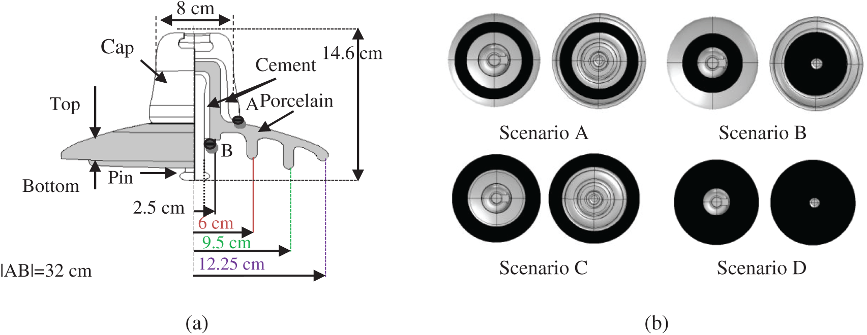
Figure 1: (a) Schematic of the insulator model; (b) Pollution distribution proposed scenarios
Table 1: Salt weight, ESDD and conductivity
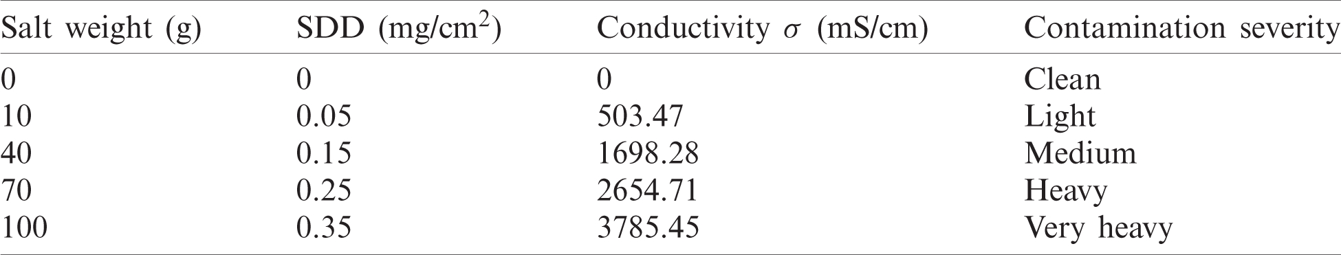
After drying of the sample insulators, they are suspended in the chamber of dimensions as 50 cm × 50 cm × 75 cm polycarbonate sheet walls. A 230 V/100 kV, 5 kVA, 50 Hz, transformer provide single-phase AC voltage up to 100 kV has been used to energize the insulators under test. The capacitive divider was used to measure the flashover voltage. Fig. 2 shows the test setup and pictorial view of the flashover voltage measurement system. The flashover voltage UF measurements were conducted under 75%, 85%, and 95% humidity controlled by fog generator. For each level of humidity and pollution, voltage rises of 2 (kV/s) and flashover measurements were conducted at least 4 times.
The average of flashover voltage UF and its relative standard deviation error σ % of N tests for each point were calculated by the following expressions [20,21].
where Ui, ni, N are the applied voltage, number of tests which were conducted at Ui and the number of the whole tests.
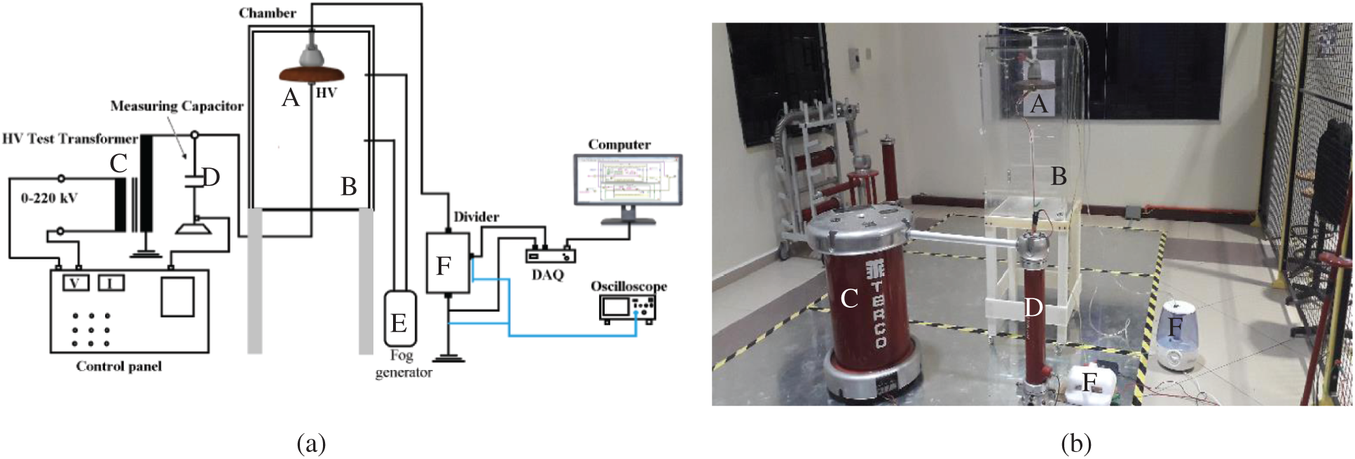
Figure 2: (a) Experimental setup circuit (b) laboratory test: A: the tested samples, B: chamber, C:transformer, D: capacitor, E: fog generator and F: control panel
3.1 Flashover Voltage of Uniform Polluted Insulator
Fig. 3 shows the flashover voltage results of the proposed scenarios for the deposit of pollutants and the location of the dry bands at three relative humidity (RH) levels of 75%, 85%, and 95%. According to the results in Fig. 3, it can be noted that the flashover voltage value of the insulator under clean conditions is 43.7 kV. Whereas, the flashover voltage value of the insulators under contamination conditions dropped sharply compared to the FOV value in its clean condition. Also, it can be observed that the relative deviation error for all tests is lower than 6.6%. The dispersion rate of flashover voltage is acceptable, which implies that the approach used in the experiments is reasonable. Under any pollution scenario, the FOV of the insulator gradually reduces with increasing SDD (pollution severity). This indicates that the relationship between the flashover voltage and the SDD has a negative power function as defined in Eq. (8) arising from the fitting of the results.
where a is constant depending on the profile and materials of the insulator and air pressure etc. while b is the characteristic indicator of contamination on the insulator. It is necessary to note that the bigger the voltage of the flashover, the better the condition of the insulator. Fig. 3a shows the relationship between the flashover voltage and SDD with various pollution severity at the humidity of 85% for scenario A. It can be seen that by increasing the SDD from 0.5 to 0.15, 2.5 and 3.5 mg/cm2 corresponding decreases in UF from 25.3 to 18.4, 14.85 and 12.62 kV, respectively. The percentage of UF value to the reference value of 43.7 kV (UF at clean condition) decreasing by 57.89%, 42.16%, 33.9% and 28.9% with increasing SDD from 0.5 to 0.15, 2.5 and 3.5 mg/cm2, respectively. For scenario B, the UF-SDD curve is shown in Fig. 3b. The flashover voltage reduces gradually with the rise of SDD. According to Fig. 3b, with increasing the SDD value from 0.5 to 0.15, 2.5 and 3.5 mg/cm2 for porcelain insulator under distribution pollution as in scenario B, the UF is lessened by 27.17%, 41.3% and 50%, respectively. The percentage of UF value to 43.7 kV as a reference value reducing by 56.3%, 37.2%, 29.2% and 24.11% at the same increase in SDD. Comparing Figs 3a and 3b, it can be observed that the influence increasing SDD in scenario A is more serious than the influence increasing SDD in scenario B on the UF under same conditions. Thus, the location of accumulation of the contamination impact the flashover creation on the percaline insulator surface. The flashover voltage percentage values to reference value for all scenarios under different pollution levels and humidity of 75% is shown in Fig. 4.
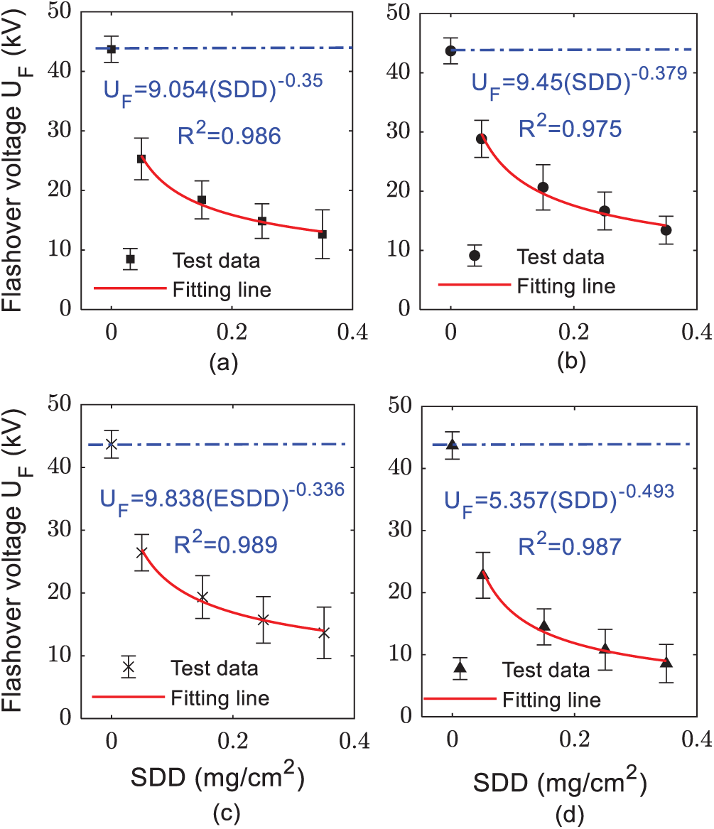
Figure 3: Flashover voltage of insulator under different modes and relative humidity of 75%: (a)Scenario A; (b) Scenario B; (c) Scenario C; (d) Scenario D
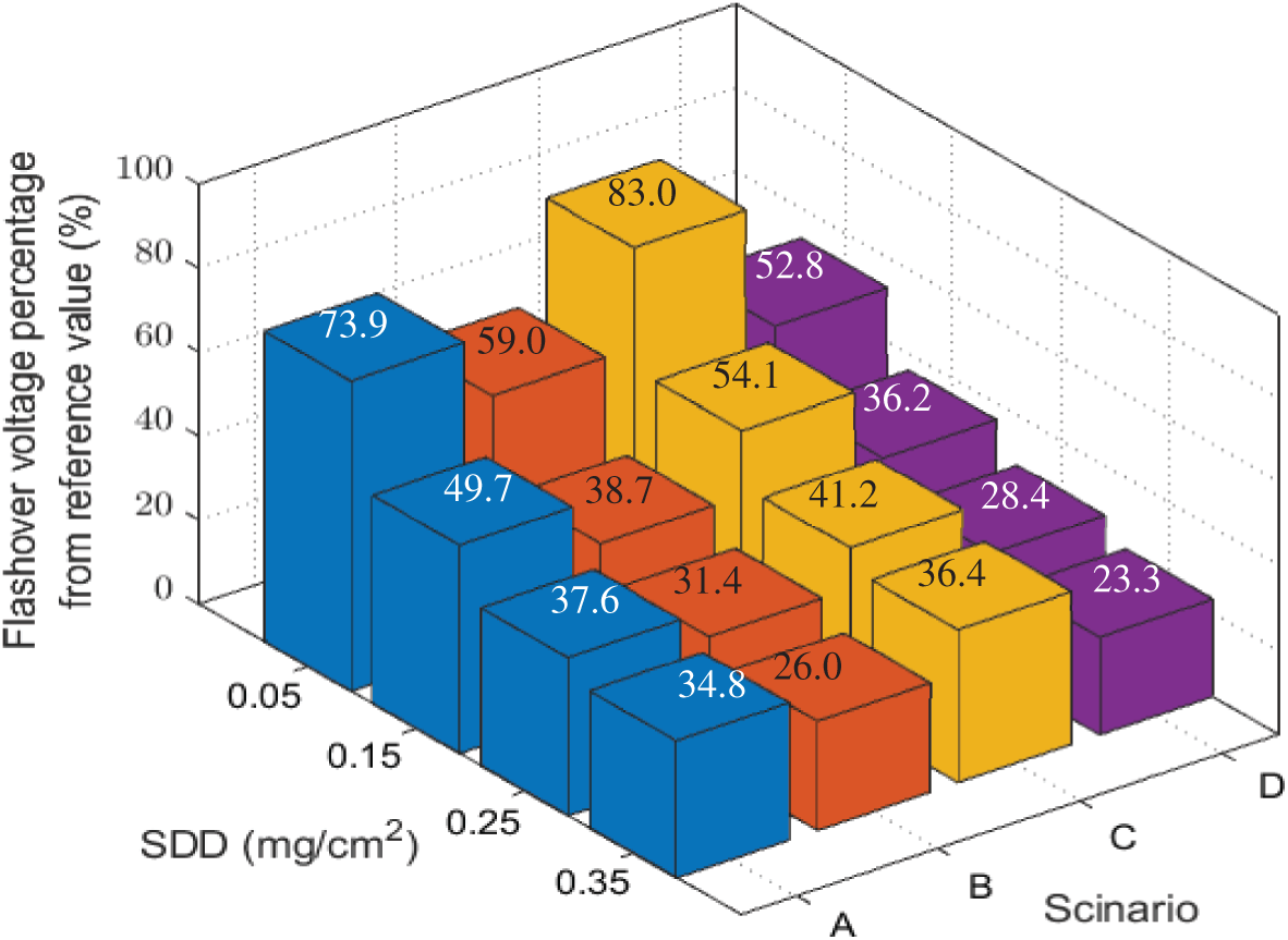
Figure 4: Percent of FOV from the reference value under different pollution and 75% RH
To estimate the influence of the contamination distribution based on proposed scenarios on the flashover voltage performance, the flashover voltage at certain pollution levels for all scenarios was compared as demonstrated in Fig. 5. The flashover voltage range of the proposed scenarios under SDD between 0.05 and 0.35 mg/cm2 can be observed from the box plot as shown in Fig. 6. This can provide useful information for understanding the conditions of the insulator under various scenarios of contamination distribution. It can be seen that the flashover voltage median has the minimum value of 14.11 kV in scenario D. This implies that as SDD increases, the insulator reaches into the serious condition faster, and thus the probability of occurrence of flashover increases. While the maximum value for the median of flashover voltage is in scenario C by 20.8 kV. The operating voltage of the measured insulator of 11 kV. Consequently, from Fig. 6 It can be seen that the minimum flashover voltage value in scenario D is less than 11 kV, meaning that they flashover occurs at a voltage less than the operating voltage which can lead to out of operation of the transmission line.

Figure 5: Comparison FOV for the proposed scenarios at SDD of 0.15 mg/cm2
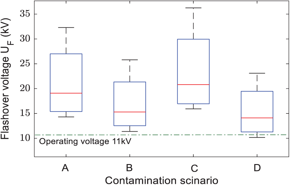
Figure 6: FOV of the proposed scenarios under RH of 75% and SDD from 0.05–0.35 mg/cm2
3.2 Effect of Humidity on Flashover Voltage
Humidity has a significant effect on contaminated insulator flashover voltage. This section addresses the influence of moisture under the proposed contaminant scenarios. Therefore, to investigate this effect, three humidity levels were selected as 75%, 85%, and 95% to simulate the possibility of humidity subjected to the actual grid insulators. Fig. 7 shows the relationship between the flashover voltage and contamination degree with different humidity levels. From Fig. 7, it can be observed that the increase in humidity leads to a decrease in the flashover voltage. The influence of humidity varies from point to point, but humidity, in general, has significantly contributed to increases in the probability of incidence of flashover. For the scenario A, under SDD equivalent of 0.15 mg/cm2, the flashover voltage of the insulator which is humidified by 85% and 95%, decreased by 3.75 and 5.5 kV, respectively. The reduction in the UF-SDD line slope with the increase in relative humidity of polluted insulators in scenarios B to D is approximately similar to the slope scenario A with some unstable portions in some cases that could be attributable to atmospheric circumstances.
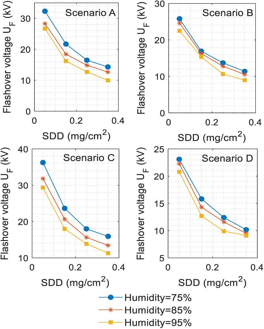
Figure 7: Flashover voltage of insulator for the proposed scenarios under different humidity
3.3 Flashover Voltage of Non-uniform Pollution Insulator
The experimental flashover voltage test results of the non-uniform contaminated insulator under proposed scenarios are elucidated at different levels of SDD, FB/T, and S and tabulated as in Tab. 2. The relative humidity in case of non-uniform pollution was taken as 75% for all tests. From Tab. 2, it can be seen that the maximum value of deviation error value for all test resulted in 4.4%, which means that the test output is excellent. Given the same B/T and S, to the porcelain insulator reduced the UF significantly with the rise of the SDD level. For example, when B/T is 3 and S is 40%, the flashover voltage of insulator under scenario SC-D decreases by 23.61% and 18.9% when the amount of SDD is increased from 0.05 to 0.015 mg/cm2 and 0.25mg/cm2 respectively. The relationship between flashover voltage UF and SDD with different values of B/T and S in scenario D (for example) are plotted in Fig. 8.
Table 2: Experimental flashover voltage test results under the proposed scenarios

The flashover voltage on the porcelain insulator surface is linked to the contamination non-uniformity B/T at the bottom and top sides. The effects of B/T and S on flashover voltage with change of the pollution level SDD are illustrated in the three-dimensional diagrams given by Figs. 9a and 9b. Meanwhile, the effects both of B/T and S on UF at SDD 0.15 mg/cm2 are shown in Fig. 9c. According to the results in Fig. 9, The UF increases gradually with the raise of B/T. Scenario D if taken as an example, there the UF resulted in 21.6, 23.8, 26.04, and 29.6 kV when SDD is 0.05 mg/cm2, S is 40% and B/T is 1, 3, 5, 8 respectively. The findings reveals that the flashover voltage has increased by 9.9%, 18.86% and 33.96% as the B/T change from 1 to 3, 5 and 8, respectively.
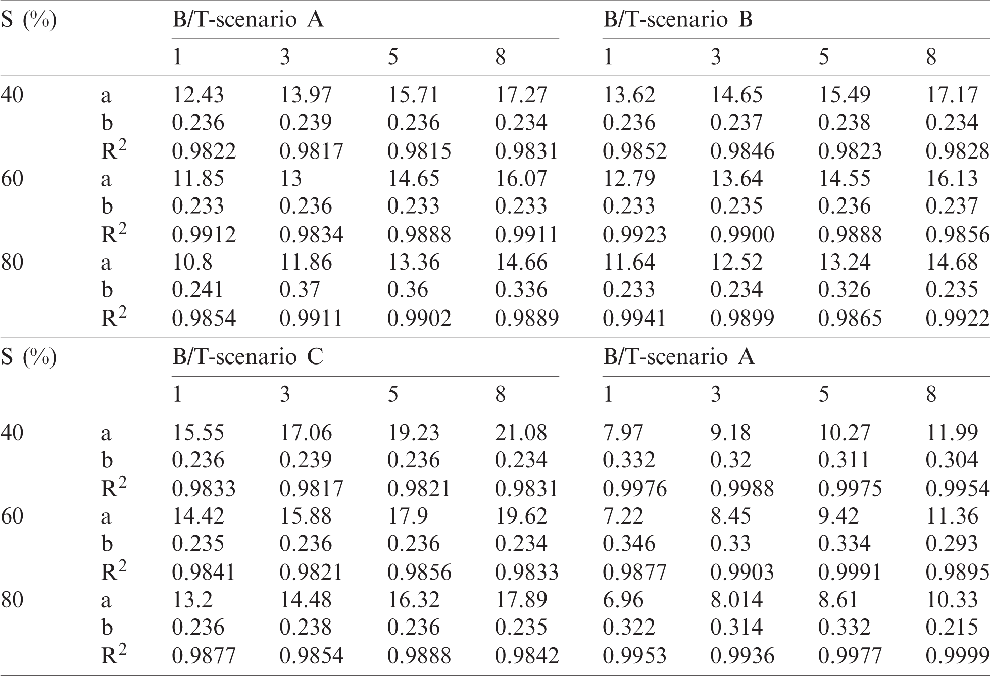
The ratio of the contaminated area to the total area of the porcelain insulators S also effects the amplitude of the flashover voltage. There is a small reduction in the UF with S raise steadily under a specific value of SDD, and B/T. While taking the scenario Type B, as an example, when SDD is 0.15 mg/cm2, B/T is 5 and S is 40%, 60%, 80%, the flashover voltage value is 31.6, 29.41 and 26.82 kV correspondingly, which denotes that the flashover voltage reduces by 7.6% when S increases by 20%. To assess the non-uniform contamination influence on insulator under test, with the flashover voltage, the test results of the porcelain insulator under the proposed scenarios in non-uniform contamination were plotted and fitted as shown in Fig. 6. It can be observed that the coefficient R2 of all fitting lines is greater than 0.92, which implies that the flashover voltage and SDD well fitted with the power function.

Figure 8: UF-SDD curve. (a) S = 40%; (b) S = 60%; (c) S = 80%
Besides, the correlation coefficient R2, a, and b which is defined in Eq. (7) early the polluted insulator under proposed scenarios were determined and listed in Tab. 3. The value of a in case of non-uniform pollution also effected by B/T and S values. For instance, in scenario A, when S is 40% and B/T ratio is 3, 5 and 8, the value of a is 9.36, 10.34, and 12.2 respectively, which implies that the a value increase by 10.4% and 30.3%.
4 Artificial Neural Network Model (ANN)
The Artificial Neural Network (ANN) is among the categories of machine learning approaches focused on the training of predefined data [22–25]. The ANN involves a large number of interconnected processing units, known as neurons, which solves the issue in a cohesive way through the transfer of data. In particular, the ANN attempts to relate between both the input data and the output data by considering the implicit relationship between the factors. This network is capable of comparing learning in order to reduce their deviation error. The most popular method in ANN preparation is the back-propagation system. This approach operates on the basis of the back-propagation algorithm. The ANN is sensitive to the link weights values between the input and output data. In order to minimize the error, the connection weights between the neurons are modified.

Figure 9: (a) The flashover voltage of scenario D (a) SDD and S under FB/T = 3. (b) SDD and FB/T under S = 40%. (c) FB/T and S under SDD = 0.15 mg/cm2
The weights are modified as per the given formula [26],
where wij, α and E are the connection weight between neurons i and j, the rate of training which determines the connection weight change amount, and Mean squared error (MSE) that is calculated from the following formula [27],
where yi and yi∗ are the observed and expected values of the model, respectively. n represents the number of data detected.
Table 3: Fitting results for proposed pollution scenarios
In this article, the neural Network algorithm was used and modelled to achieve maximal convergence to the minimum possible point from the back-propagation approach in MATLAB, after which this model was learned and evaluated. The UF was estimated as ANN output. The inputs of the model were SDD, B/T, S and relative humidity as shown in Fig. 10. Many contamination flashover tests were conducted on the porcelain insulator under different scenarios of pollution with uniform and non-uniform contamination, as mentioned in the experiment setup section. In this model, 432 data of UF were recorded. 70% of them (302 data) is chosen to the model training, 15% of them (65 data) is utilized for model performance verification, and 15% also (65 data) is chosen for the model testing. To minimize prediction errors, input and target data is normalized prior to training according on the following equation [28]:
where γi∗ is normalized data of γi, γmax is the maximum value of γi, and γmin is the minimum value of γi. Fig. 11a displays the number of instances of particular errors in the instruction, evaluation and test data of the neural network collected. For a large volume of data, the density of values obtained is around zero. The MSE for the training, validation, and test of the model was obtained and displayed in Fig. 11b. The optimum response was observed in the model at epoch 58 that the MSE was around 0.657.
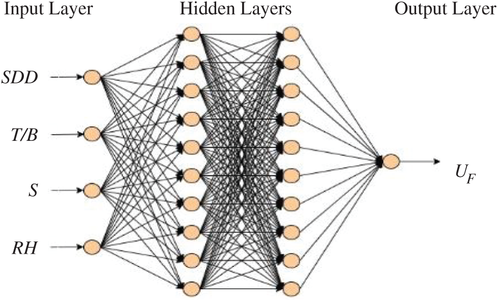
Figure 10: Artificial neural network structure
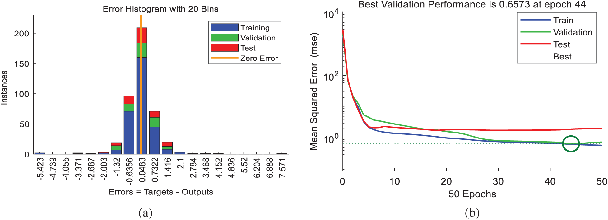
Figure 11: (a) Number of training, validation and test data in the specific errors; (b) MSE and optimal point

Figure 12: Training, validation, test and all data regression
The (Training, Validation, and Test) regression outcomes of the model are demonstrated in Fig. 12. It can be seen that the R2 of overall regression is more than 0.98 that induced is the model performance is satisfactory. Fig. 13 shows the comparison between test and model predict results with error. It can be noted that the error between the experiment and model results does not exceed 1.5. Therefore, the artificial neural network model introduced is able to predict effectively.
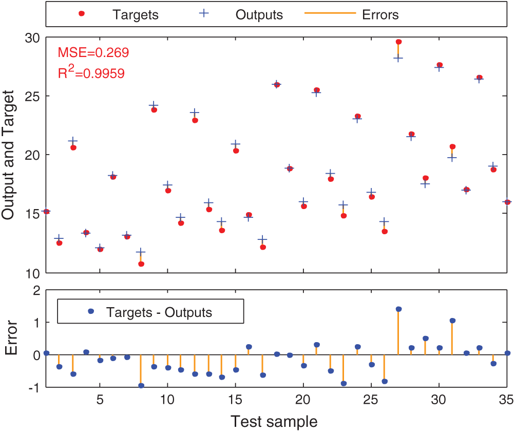
Figure 13: Comparison between the test data with the model prediction
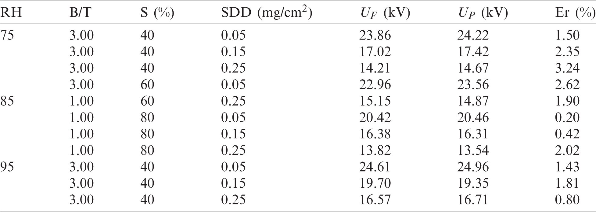
For the verification of the proposed ANN model forecast, the test results of three other types of non-uniform distribution of contamination are chosen. The test results of non-uniform contamination on bottom surfaces, non-uniform contamination on top surfaces, and non-uniform contamination which cover whole surfaces are selected to verify the proposed model. The ANN model prediction results and the test results are listed in Tab. 4. The relative error between test and predict results is calculated as,
It can be observed the relative error is less than 3%, this indicate the predicting method using the proposed ANN model has the good performance.
Table 4: Experiment and ANN model results
This paper introduces a comprehensive study on the flashover performance of porcelain insulators under different contamination and humidity levels in four scenarios of the pollution distribution is carried out. The flashover voltage of clean and polluted insulators was analyzed during the experimental tests and the impact of humidity, dry band, and pollution severity on flashover voltage was precisely investigated. It was noticed that the flashover voltage is significantly impacted by SDD, area, and location of dry band as well as humidity. The results revealed that, the UF-SDD interaction always follows a negative power feature when the insulator is contaminated. The flashover voltage decreases with an increase in the polluted area on the insulator surface. According to experimental results it was observed that the insulator had the smallest value of flashover value under scenario E compared to other scenarios. In addition, the flashover voltage drops too with the rise in humidity. The ANN model has been proposed to predict the flashover voltage. The proposed model was compared with the test results. The relative errors between test and prediction data were calculated. The error values appeared to be less than 3% that indicates the use of proposed ANN technique is efficient and accurate for predicting the flashover voltage on porcelain insulators under the proposed scenarios.
Funding Statement: The authors received no specific funding for this study.
Conflicts of Interest: The authors declare that they have no conflicts of interest to report regarding the present study.
1. M. Wakhidin and P. Suwarno, “Effects of artificial tropical climate aging on insulation performance of silicone rubber polymeric insulators,” in Proc. 2nd Int. Conf. on High Voltage Engineering and Power Systems, Indonesia, pp. 4–9, 2019. [Google Scholar]
2. A. Banik, A. Mukherjee and S. Dalai, “Development of a pollution flashover model for 11 kV porcelain and silicon rubber insulator by using COMSOL multiphysics,” Electrical Engineering, vol. 100, no. 2, pp. 533–541, 2018. [Google Scholar]
3. T. Yuan, Q. Yang, K. Xu and C. Sun, “Effect of non-uniform pollution on the withstand characteristics of extra high voltage (EHV) suspension ceramic insulator string,” IET Generation, Transmission & Distribution, vol. 4, no. 3, pp. 445–455, 2010. [Google Scholar]
4. X. Qiao, Z. Zhang, X. Jiang and D. Zhang, “Contamination characteristics of typical transmission line insulators by wind tunnel simulation,” Electric Power Systems Research, vol. 184, no. 174, pp.106288,2020. [Google Scholar]
5. A. Salem, R. Abd-Rahman, S. Al-Gailani, M. Kamarudin, H. Ahmad et al., “The leakage current components as a diagnostic tool to estimate contamination level on high voltage insulators,” IEEE Access, vol. 8, pp. 92514–92528, 2020. [Google Scholar]
6. Z. Zhang, D. Zhang, W. Zhang, C. Yang, X. Jiang et al., “DC flashover performance of insulator string with fan-shaped non-uniform pollution,” IEEE Transactions on Dielectrics and Electrical Insulation, vol.22, no. 1, pp. 177–184, 2015. [Google Scholar]
7. Z. Zhang, X. Liu, X. Jiang, J. Hu and D. Gao, “Study on AC flashover performance for different types of porcelain and glass insulators with non-uniform pollution,” IEEE Transactions on Power Delivery, vol. 28, no. 3, pp. 1691–1698, 2013. [Google Scholar]
8. A. Salem, R. Abd-Rahman, S. Al-Gailani, M. Kamarudin, N. Othman et al., “Artificial intelligence techniques for predicting the flashover voltage on polluted cup-pin insulators,” in Advances in Intelligent Systems and Computing. Berlin, Germany: Springer, pp. 362–372, 2019. [Google Scholar]
9. A. Salem, R. Abd-Rahman, M. Kamarudin and N. A. Othman, “Factors and models of pollution flashover on high voltage outdoor insulators: Review,” in Proc. 2017 IEEE Conf. on Energy Conversion, Kuala Lampur, Malaysia, pp. 241–246, 2017. [Google Scholar]
10. J. Samakosh and M. Mirzaie, “Investigation and analysis of ac flashover voltage of sir insulators under longitudinal and fan-shaped non-uniform pollutions,” International Journal of Electrical Power & Energy Systems, vol. 108, no. 11, pp. 382–391, 2019. [Google Scholar]
11. E. Savadkoohi, M. Mirzaie, S. Seyyedbarzegar, M. Mohammadi, M. Khodsuz et al., “Experimental investigation on composite insulators ac flashover performance with fan-shaped non-uniform pollution under electro-thermal stress,” International Journal of Electrical Power and Energy Systems, vol. 121, no.5, pp. 106142, 2020. [Google Scholar]
12. A. Arshad, S. Nekahi, G. McMeekin and M. Farzaneh, “Numerical computation of electric field and potential along silicone rubber insulators under contaminated and dry band conditions,” 3D Research, vol. 7, no. 3, pp. 25, 2016. [Google Scholar]
13. R. Abd-Rahman, A. Haddad, M. Kamarudin, M. Yousof and N. Jamail, “Dynamic modelling of polluted outdoor insulator under wet weather conditions,” in Proc. 2016 IEEE Int. Conf. on Power and Energy, Melaka, pp. 610–614, 2016. [Google Scholar]
14. M. Bouhaouche, A. Mekhaldi and M. Teguar, “Improvement of electric field distribution by integrating composite insulators in a 400 kV AC double circuit line in algeria,” IEEE Transactions on Dielectrics and Electrical Insulation, vol. 24, no. 6, pp. 3549–3558, 2017. [Google Scholar]
15. Z. Zhang, Y. Shenghuan, J. Xingliang, Q. Xinhan and X. Yingzhu, “DC flashover dynamic model of post insulator under non-uniform pollution between windward and leeward sides,” Energies, vol. 12, no. 12, pp. 2345, 2019. [Google Scholar]
16. G. Asimakopoulou, V. Kontargyri, Ch. Elias, G. Tsekouras and F. Asimakopoulou, “A fuzzy logic optimization methodology for the estimation of the critical flashover voltage on insulators,” Electric Power Systems Research, vol. 81, no. 2, pp. 580–588, 2010. [Google Scholar]
17. S. Bessedik and H. Hadi, “Prediction of flashover voltage of insulators using least squares support vector machine with particle swarm optimization,” Electric Power Systems Research, vol. 104, no. 11, pp. 87–92, 2013. [Google Scholar]
18. A. Salem, R. Abd-Rahman, M. Kamarudin, H. Ahmad, N. Jamail et al., “Proposal of a dynamic numerical approach in predicting flashover critical voltage,” International Journal of Power Electronics and Drive Systems, vol. 10, no. 2, pp. 602, 2019. [Google Scholar]
19. L. Jin, J. Ai, Z. Tian and Y. Zhang, “Detection of polluted insulators using the information fusion of multispectral images,” IEEE Transactions on Dielectrics and Electrical Insulation, vol. 24, no. 6, pp.3530–3538,2017. [Google Scholar]
20. A. Salem and R. Abd-Rahman, “A review of the dynamic modelling of pollution flashover on high voltage outdoor insulators,” Journal of Physics: Conference Series, vol. 1049, pp. 12–19, 2018. [Google Scholar]
21. A. Salem, R. Abd-Rahman, H. Ahmad, M. Kamarudin, N. Jamal et al., “A new flashover prediction on outdoor polluted insulator using leakage current harmonic components,” in Proc. IEEE 7th Int. Conf. Power Energy, Malaysia, pp. 413–418, 2019. [Google Scholar]
22. N. N. Hamadneh, W. Khan, W. Ashraf, S. H. Atawneh and I. Khan, “Artificial neural networks for prediction of covid-19 in Saudi Arabia,” Computers, Materials & Continua, vol. 66, no. 3, pp.2787–2796,2021. [Google Scholar]
23. A. Sarkar and P. Pandey, “River water quality modelling using artificial neural network technique,” Jurnal Aquat Procedia, vol. 4, pp. 1070–1077, 2015. [Google Scholar]
24. P. Tahmasebi and A. Hezarkhani, “A hybrid neural networks-fuzzy logic-genetic algorithm for grade estimation,” Computers & Geosciences, vol. 42, no. 1, pp. 18–27, 2012. [Google Scholar]
25. A. Abbasi, A. Shayegani and K. Niayesh, “Contribution of design parameters of sir insulators to their DC pollution flashover performance,” IEEE Transactions on Power Delivery, vol. 29, no. 4, pp.1814–1821,2014. [Google Scholar]
26. P. Rocha, E. Costa, A. Serres, G. Xavier, J. Peixoto et al., “Inspection in overhead insulators through the analysis of the irradiated RF spectrum,” International Journal of Electrical Power and Energy Systems, vol. 113, pp. 355–361, 2019. [Google Scholar]
27. O. Gouda and D. Khalifa, “Online monitoring of medium voltage overhead distribution lines polluted insulators severity,” CIRED Open Access Proceedings Journal, vol. 17, no. 1, pp. 372–375, 2017. [Google Scholar]
28. A. Ahmed, “Prediction of dissolved oxygen in Surma River by biochemical oxygen demand and chemical oxygen demand using the artificial neural networks (ANNs),” Journal of King Saud University-Engineering Sciences, vol. 29, no. 2, pp. 151–158, 2017. [Google Scholar]
 | This work is licensed under a Creative Commons Attribution 4.0 International License, which permits unrestricted use, distribution, and reproduction in any medium, provided the original work is properly cited. |