DOI:10.32604/cmc.2021.015421
| Computers, Materials & Continua DOI:10.32604/cmc.2021.015421 | |
| Article |
A Highly Efficient Algorithm for Phased-Array mmWave Massive MIMO Beamforming
1Department of Electrical Engineering, Jouf University, Sakaka, Aljouf, 72388, Kingdom of Saudi Arabia
2Department of Computer and Communication Systems Engineering, Faculty of Engineering, Universiti Putra Malaysia (UPM), Serdang, 43400, Malaysia
3Department of Electrical Engineering, University of Engineering and Technology Peshawar, Pakistan
4School of Electrical and Electronics Engineering, Chung-Ang University, Seoul, 06974, Korea
5Electrical and Electronic Department, Kwame Nkrumah University of Science and Technology, Kumasi, Ghana
6UMR 1253, iBrain, Université de Tours, INSERM, Tours, France
7LIMPAF Laboratory, Department of Computer Science, University of Bouira, Bouira, 10000, Algeria
8University of Tours (France), GREMAN UMR 7347, CNRS, INSA Centre Val-de-Loire, Tours, 37100, France
*Corresponding Author: Abdeldjalil Ouahabi. Email: ouahabi@univ-tours.fr
Received: 20 November 2020; Accepted: 30 December 2020
Abstract: With the rapid development of the mobile internet and the internet of things (IoT), the fifth generation (5G) mobile communication system is seeing explosive growth in data traffic. In addition, low-frequency spectrum resources are becoming increasingly scarce and there is now an urgent need to switch to higher frequency bands. Millimeter wave (mmWave) technology has several outstanding features—it is one of the most well-known 5G technologies and has the capacity to fulfil many of the requirements of future wireless networks. Importantly, it has an abundant resource spectrum, which can significantly increase the communication rate of a mobile communication system. As such, it is now considered a key technology for future mobile communications. MmWave communication technology also has a more open network architecture; it can deliver varied services and be applied in many scenarios. By contrast, traditional, all-digital precoding systems have the drawbacks of high computational complexity and higher power consumption. This paper examines the implementation of a new hybrid precoding system that significantly reduces both calculational complexity and energy consumption. The primary idea is to generate several sub-channels with equal gain by dividing the channel by the geometric mean decomposition (GMD). In this process, the objective function of the spectral efficiency is derived, then the basic tracking principle and least square (LS) techniques are deployed to design the proposed hybrid precoding. Simulation results show that the proposed algorithm significantly improves system performance and reduces computational complexity by more than 45% compared to traditional algorithms.
Keywords: 5G; mmWave; phased array; algorithm; antenna beamforming
As the number of wireless devices continues to grow and wireless applications continue to expand, user demand for wireless network transmission rates continues to increase. The existing low frequency network (<3 GHz) is struggling to meet this increasing demand for speed. Addition, it is oriented towards greater bandwidth. High frequency resources are currently being studied and implemented [1] and the 60 GHz millimeter wave (mmWave) has aroused the interest of a large number of researchers. Many countries have opened unlicensed 60 GHz mmWave frequency bands for research and testing. For example, China’s open frequency band is 59~64 GHz, in the United States the band is 57~64 GHz, and Japan uses 59~66 GHz. Relevant standards have been established to promote the industrialization of 60 GHz mmWave applications [2–6]. Wireless HD (WiHD) is primarily used to achieve high-quality, high-definition, uncompressed video transmission indoors, while the IEEE802.15.3c standard is primarily used for high-quality indoor networks. Wireless personal area network (WPAN) applications and the IEEE802.11.ad standard provide high-quality wireless local area network (WLAN) applications [7].
The application of the 60 GHz mmWave band presents significant challenges. Oxygen attenuation on the ground reaches 15 dB/km as a result of the oxygen attenuation window. In addition, reflection attenuation and other losses occur as part of the propagation process. As such, the link budget is very limited and if we are in a non-line-of-sight (NLOS) environment, the performance of the link will be severely affected [8]. Furthermore, the output power of the power amplifier in the 60 GHz mmWave frequency band is very limited. Therefore, exploitation of the short wavelength region and small antenna arrays in this frequency band, as well as the use of beamforming technology, can help improve link gain. In terms of implementation methods, beamforming technology can be divided into adaptive beamforming and fixed beamforming [9]. Although adaptive beamforming technology performs well, the complexity of its implementation is high. The implementation of codebook-based fixed beamforming technology is not very complex, but unfortunately it is not very efficient. In terms of hardware architecture, digital beamforming technology is generally used. Each antenna is configured with a radio frequency link, which sees high costs and power consumption [10]. MmWave generally adopts radio frequency beamforming technology and realizes the alignment of the transceiver through the radio frequency phase shifter to directly adjust the signal, reducing the cost [11,12]. MmWave beamforming technology has been the subject of numerous studies. The IEEE802.11.ad and IEEE802.15.3c standards both adopt codebook-based beamforming technology as part of the RF phase-shifting architecture and find an optimal beam through hierarchical searching [13–16].
In recent years, mmWave massive multiple-input multiple-output (massive-MIMO) technology has attracted the attention of the scientific community. This is primarily because mmWave communications present an abundant spectrum and hybrid massive-MIMO precoding technology provides a higher beam gain and compensates for the propagation defect of the high loss of mmWave communications [17]. However, at the same time, the scale of the hardware required and the complexity of encoding and decoding are both increasing and a new hybrid precoding scheme is needed to reduce system complexity.
MIMO multiplexing systems typically use singular value decomposition (SVD) to obtain several independent orthogonal spatial sub-channels for higher throughput. However, due to the large differences in the gain of each sub-channel in this method, it is necessary to use different codecs and modulation/demodulation methods to meet the bit error rate (BER) requirements, making the system very complex [18]. For this reason, the authors of [19] propose a scheme based on geometric mean decomposition (GMD). This scheme decomposes the Rayleigh fading channel under orthogonal frequency division multiplexing into several parallel sub-channels with equal channel gains. This helps to avoid complicated bit allocation and power loading processes and reduces the difficulty of system encoding and decoding, reducing overall system complexity [20]. In order to obtain a hybrid precoding scheme with the best frequency efficiency, the authors in [21] transformed the frequency efficiency optimization problem into a sparse approximation problem and optimized it using the orthogonal matching pursuit (OMP) algorithm to downlink the frequency efficiency of a single-user MIMO system [22]. The authors of [23] studied the frequency efficiency of a single-user MIMO system and designed a hybrid precoding scheme, proposing an algorithm to optimize the frequency efficiency of the system. However, they only considered the optimization of the algorithm and did not proceed in terms of the complexity of the coding and decoding of the system. After studying MIMO channel diagonalization, the authors of [24] used the GMD method to efficiently compensate for gain difference defects in SVD-weighted sub-channels. The authors of [25] examined the impact of the differential GMD precoder on the frequency efficiency of the system based on the assumption of a low feedback rate in single-user MIMOs, but the relationship between the frequency efficiency of the system and the number of BS antennas and the signal-to-noise ratio remains unclear and would be difficult to promote in the current communications environment.
Based on the current state of research on the spectral efficiency of the millimeter wave MIMO downlink system, the GMD channel processing method was applied to the processing of Saleh-Valenzuela mmWave channels. Compared to the traditional SVD algorithm, the complexity of the system can be effectively reduced and, for the single-user mobile downlink communication scenario, the hybrid GMD-based precoding scheme is proposed and implemented. This scheme can give good results, assuming that the system complexity can be reduced and the spectral efficiency can be improved.
Fig. 1 shows the proposed modeling of the mmWave Massive-MIMO system. To simplify the analysis, the system only takes into account the downlink transmission scenario of a single cell and a single user. The base station is configured with
The hybrid precoding, which is performed at the base station, consists of digital precoding,
where
In the previous equations, (·)H is the complex conjugate transposition operation;
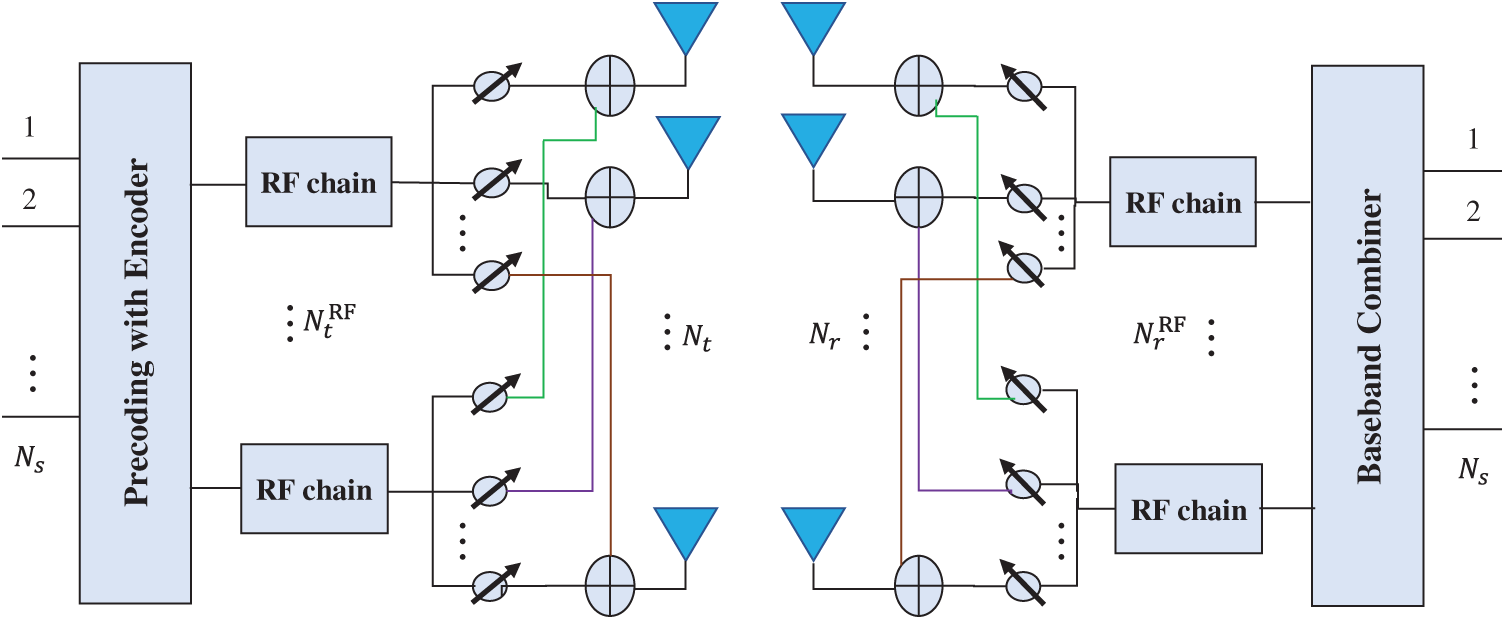
Figure 1: Proposed system model
The mmWave channel follows the Saleh Valenzuela channel model, and the channel transfer matrix
In (3),
For a simple uniform linear array (ULA) containing
In (4),
The limited spatial scattering of the propagating mmWave considerably varies the singular value of the channel matrix
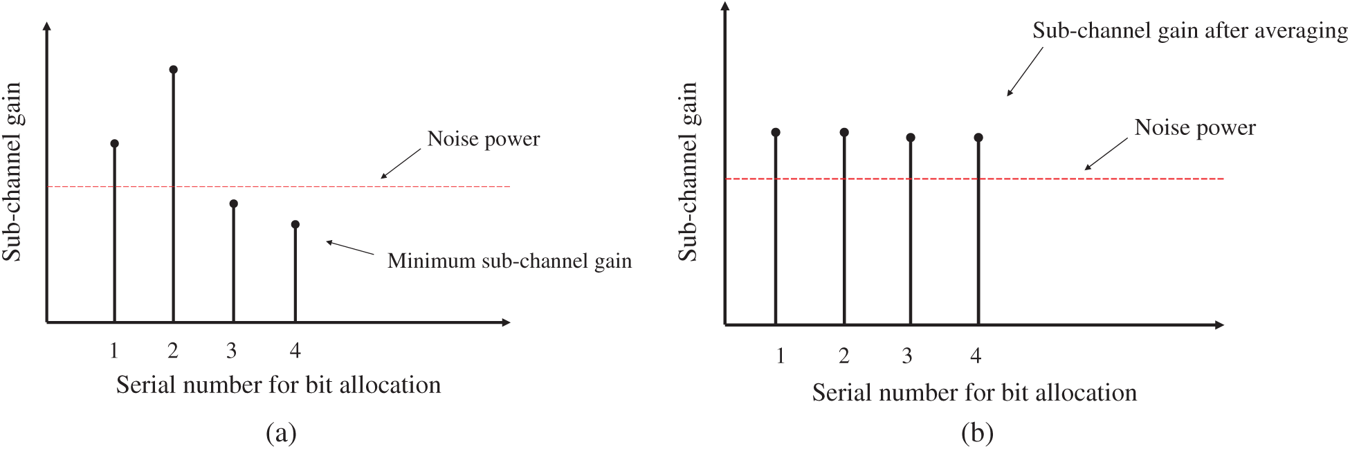
Figure 2: Illustration of sub-channel gain. (a) traditional SVD precoding; (b) GMD precoding
In the same modulation/demodulation mode, the bit error rate (BER) of all sub-channels is determined by the sub-channel with the lowest fixed SNR. In order to ensure that all sub-channels maintain a similar bit error rate, the SVD-based precoding system requires careful bit allocation for each sub-channel, which will greatly increase the complexity of the system encoding/decoding process [29]. However, the
From (2), the spectral efficiency of the system is defined by (5) [30].
3.2 Optimization of Spectral Efficiency
From (5), we can see that for any arbitrary value having a rank of
In (6),
From (6), the
Assuming that
1. The matrix
2. Moreover, since the singular value of
Substituting Eq. (8) into Eq. (7), we obtain Eq. (9).
In (9), the first term can be obtained by setting
Assuming that
3.3 Conversion Optimization Objective Function
To reduce the complexity of the GMD transformation and obtain the optimized solution of Eq. (10), the optimization problem can be transformed by Lemma 1.
Lemma 1: Suppose the SVD of the channel matrix
The singular values of the channel matrix are arranged in descending order, then there is a unit matrix
Lines of evidence: Calculate the geometric mean of the channel matrix
In the previous equation, “
where
Update
Further:
This shows that through
Eq. (15) shows that
According to Lemma 1, the right side of Eq. (10) can be rewritten as (17).
The condition that the third step of the Eq. (17) holds is because the F-norm remains unchanged under the matrix rotation, and there is a
Substituting Eq. (17) into Eq. (10), we can get (18).
So far, the objective function (i.e., Eq (10)) has been effectively transformed.
3.4 Optimize Objective Function Solution
From (18), although
In (19),
Eq. (19) is a sparse reconstruction problem, which can be solved by tracking the bases [6]. When the analog precoding matrix
The optimal solution of Eq. (20) is presented in the form of an LS method (see (21)) [26].
Furthermore:
According to the derivation of the LS matrix:
According to the above analysis, the problem of selecting the optimal analog precoding matrix is a sparse reconstruction problem, which can be solved by the basic tracking principle. After obtaining the analog precoding, the LS method is used to optimize the solution method in order to obtain the optimal digital precoding matrix
4 Hybrid Precoding Optimization Algorithm Based on GMD
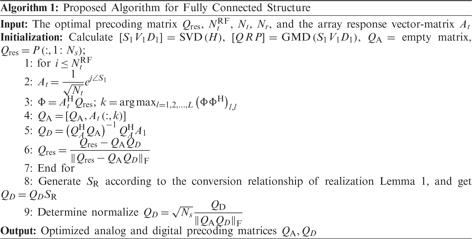
4.1 Optimization Algorithm Under Fully Connected Structure
In the fully connected structure, hybrid precoding only takes into account the base station coding, and the user receiver can perform the corresponding decoding processing based on the received signal. The optimal solution algorithm of Eq. (18) consists of two links. The first one uses the for loop to use the residual matrix
It should be pointed out that due to the calculation using the conversion relation in Lemma 1, it is not necessary to calculate
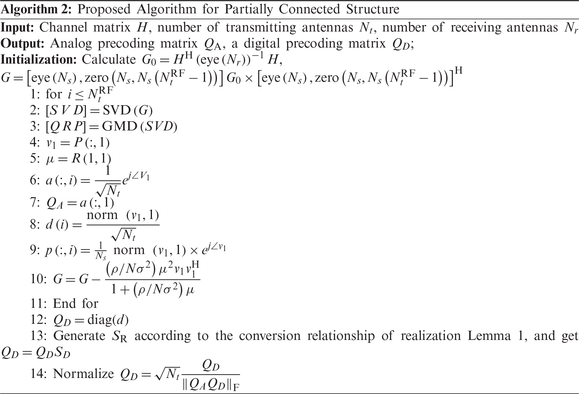
4.2 Optimization Algorithm Under Partially Connected Structure
Under the partially connected structure, the previous step of the hybrid precoding optimal solution algorithm is to transform the channel
In Algorithm 2, the computational complexity of generating the auxiliary matrix
This section analyses the performance of the GMD-based hybrid precoding scheme and spatial sparse precoding through simulation. The simulation environment is set as follows: the base station adopts ULA transmitting antenna array, the number of antennas is 64 and 256, respectively, the number of user end antennas is 16 and 64, and the antenna interval
Fig. 3 shows the spectral efficiency performance of the proposed Algorithm 1 under different iterations when the number of transmitting antennas is 256 and the number of receiving end antennas is 64. It can be seen from Fig. 3 that as the number of iterations increases, spectral efficiency gradually increases. When the number of iterations reaches 100, Algorithm 1 converges. It shows that the proposed algorithm is feasible for spectral efficiency under the GMD channel processing method.
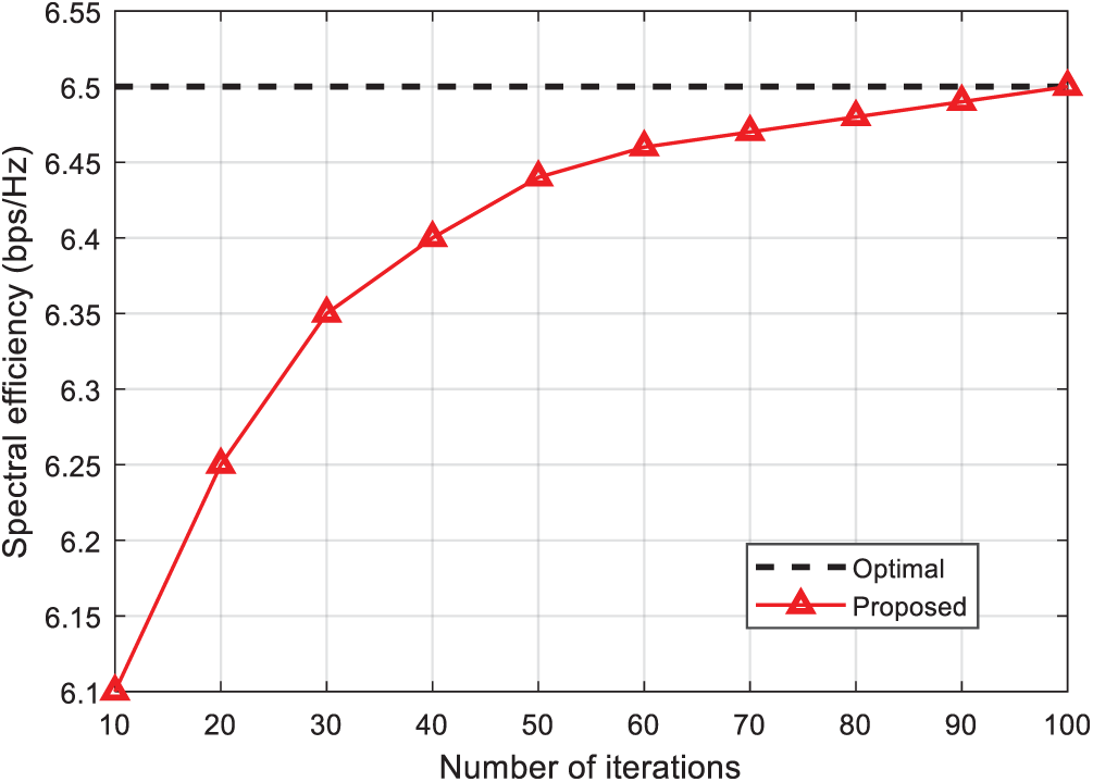
Figure 3: Comparison of spectral efficiency under different number of iterations
Fig. 4 shows the comparison of the spectral efficiency with SNR when the number of RF chains at both ends is 8 and the transmission data streams
The spectral efficiency obtained by the GMD-based hybrid precoding method when the number of base station antennas is better than the reference scheme [21].
2)As the number of transmitting antennas increases, the spectral efficiency of the system gradually increases. With the increase of the SNR, the increase of the spectral efficiency becomes progressively more important, which means that the larger the scale of the antenna, the better the spectral efficiency performance, but due to the limitation of the maximum transmit power, the increase of the effect has extreme values.
3)When the number of base station antennas increases to a certain value, the proposed scheme can approach the optimal precoding performance.
Fig. 5 shows the comparison of the spectral efficiency performance with SNR in the two antenna connection modes when the number of RF chains at both ends is 8, the transmission data stream
1. Under the partial connection structure, the performance of the GMD-based hybrid precoding scheme is better than the traditional analog precoding;
2. The spectral efficiency performance of the proposed precoding scheme is equivalent to the optimal precoding scheme under the partial connection structure, indicating that the proposed scheme has achieved near-optimal performance;
3. When the SNR reaches 10 dB, the spectral efficiency of the proposed scheme under the partially connected transmission structure is approximately 80% of the scheme in [21] in the fully connected structure.
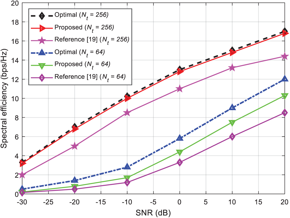
Figure 4: Spectral efficiency performance of fully connected structure system under different SNR
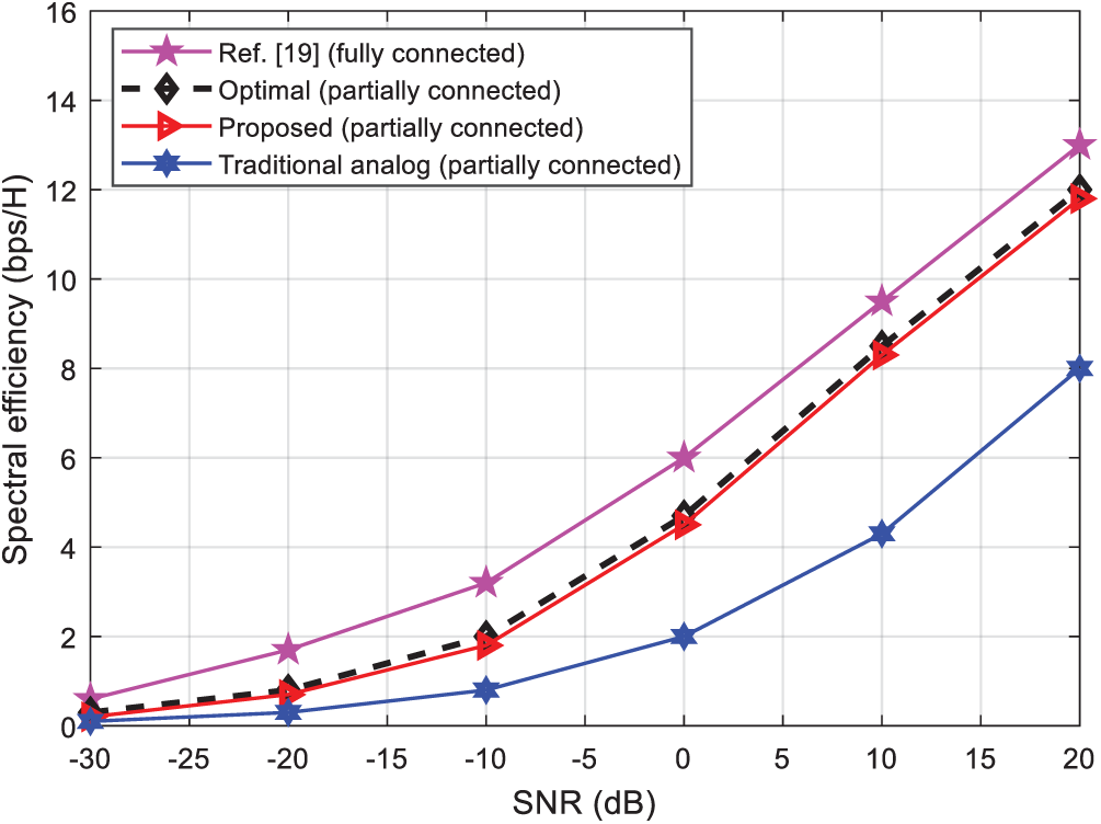
Figure 5: Spectral efficiency performance under different connection structures
Overall, the proposed system has good scalability and spectral efficiency, which guarantees the complexity of the system.
Fig. 6 compares the computational complexity of the algorithms under an increasing number of RF chains. As shown in Fig. 6, the complexity of all algorithms increases with the increasing number of RF chains. In addition, the complexity of the proposed hybrid precoding system has reduced performance compared to the optimal precoding system, which means that the proposed system is computationally efficient and requires a lower number of iterations and information signal processing time. On the other hand, the reference analog precoding scheme [21] and the traditional analog precoding scheme are very complex.
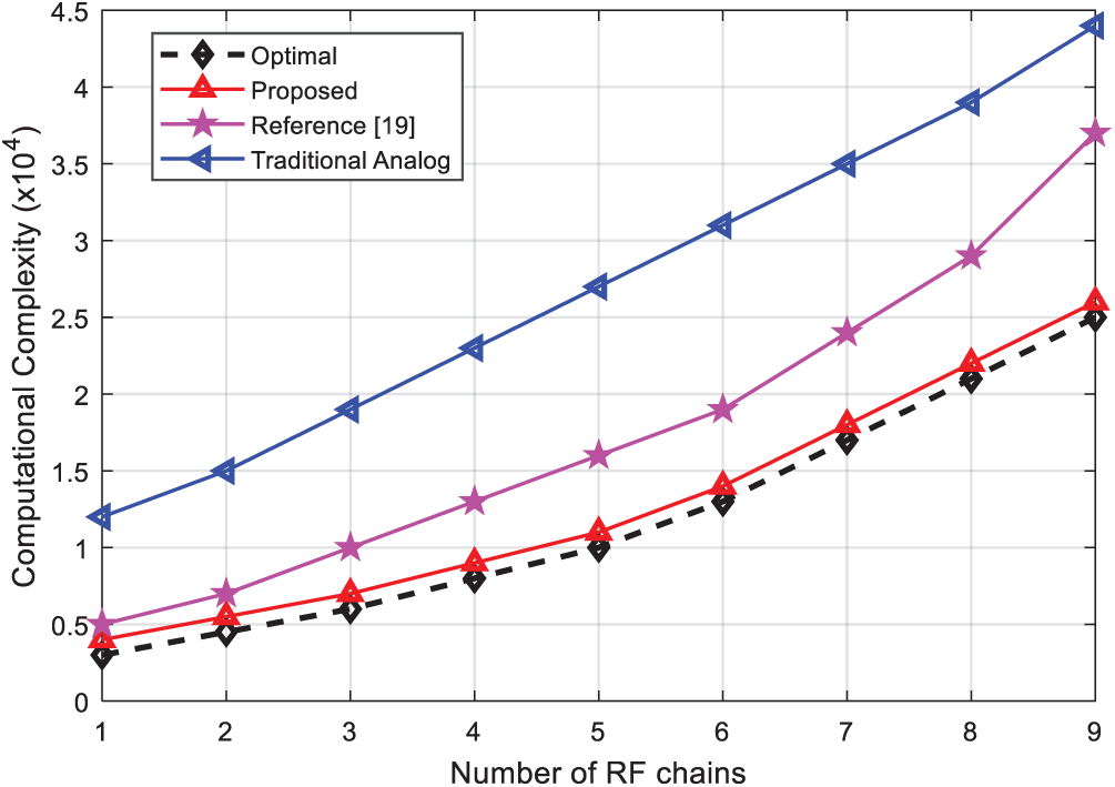
Figure 6: Complexity comparison of the algorithms vs. the number of RF chains
Millimeter wave (30 GHz–300 GHz) is used for high-speed (5G) wireless communications by allocating more bandwidth to deliver faster and higher quality video and multimedia content and services.
Due to the significant changes in the signal-to-noise ratio of the different sub-channels in the singular value decomposition, which leads to increased system complexity and encoding/decoding difficulties, a hybrid precoding scheme, which is based on geometric mean decomposition (GMD), is proposed.
Compared to the system proposed by [28], the hybrid precoding system proposed here can effectively equalize the signal-to-noise ratio of the sub-channels and reduce the overall complexity of the system. At the same time, in order to be better applied to real communication scenarios, the code has been extended to some connection transmission structures, and better frequency performance has also been obtained. The simulation results show that the frequency efficiency of the hybrid precoding scheme proposed under different base station antenna numbers is better than that of the orthogonal matching pursuit scheme [28], and that it can be applied to both existing transmission structures with a high applicability.
In perspective, the algorithms and conclusions proposed in this paper are established under ideal channel conditions. Further research is more than necessary for more complex and universal communication scenarios.
Funding Statement: The authors received no specific funding for this study.
Conflicts of Interest: The authors declare that they have no conflicts of interest to report regarding the present study.
1. S. Bashir, M. H. Alsharif, I. Khan, M. A. Albreem, A. Sali et al., “MIMO-Terahertz in 6G nano-communications: Channel modeling and analysis,” Computers, Materials & Continua, vol. 66, no. 1, pp. 263–274, 2020. [Google Scholar]
2. A. Amin, X. Liu, I. Khan, P. Uthansakul, M. Forsat et al., “A robust resource allocation scheme for device-to-device communications based on Q-learning,” Computers, Materials & Continua, vol. 65, no. 2, pp. 1487–1505, 2020. [Google Scholar]
3. S. Alemaishat, O. A. Saraereh, I. Khan, S. H. Affes, X. Li et al., “An efficient precoding scheme for millimeter-wave massive MIMO systems,” Electronics, vol. 8, no. 9, pp. 1–15, 2019. [Google Scholar]
4. A. Silva, S. Teodoro, R. Dinis and A. Gamero, “Iterative frequency-domain detection for IA-precoded MC-CDMA systems,” IEEE Transactions on Communications, vol. 62, no. 4, pp. 1240–1248, 2014. [Google Scholar]
5. A. Al-Nimrat, M. Smadi, O. A. Saraereh and I. Khan, “An efficient channel estimation scheme for mmwave massive MIMO systems,” in Proc. IEEE Int. Conf. on Communication, Networks and Satellite (ComNetSatMakassar, Indonesia, pp. 1–8, 2019. [Google Scholar]
6. A. Silva, J. Assuncau, R. Dinis and A. Gameiro, “Performance evaluation of IB-DFE based strategies for SC-FDMA systems,” EURASIP Journal on Wireless Communications and Networking, vol. 13, pp. 1–10, 2013. [Google Scholar]
7. I. Khan and D. Singh, “Efficient compressive sensing based sparse channel estimation for 5G massive MIMO systems,” AEU-International Journal of Electronics and Communications, vol. 89, no. 2, pp. 181–190, 2018. [Google Scholar]
8. D. Casthanheira, A. Silva, R. Dinis and A. Gameiro, “Efficient transmitter and receiver design for SC-FDMA based heterogeneous networks,” IEEE Transactions on Communications, vol. 63, no. 7, pp. 2500–2510, 2015. [Google Scholar]
9. M. H. Zafar, I. Khan and M. Basheri, “Matrix inversion-less direct decoding for efficient channel estimation fifth-generation massive MIMO systems,” IET Communications, vol. 14, no. 5, pp. 865–871, 2020. [Google Scholar]
10. D. Castanheira, A. Silva and A. Gameiro, “Set optimization for efficient interference alignment in heterogeneous networks,” IEEE Transactions on Wireless Communications, vol. 13, no. 10, pp. 5648–5660, 2014. [Google Scholar]
11. I. Khan, J. Rodrigues, J. Al-Muhtadi, M. I. Ktk, Y. Jan et al., “A robust channel estimation scheme for 5G massive MIMO systems,” Wireless Communications and Mobile Computing, vol. 3469413, pp. 1–9, 2019. [Google Scholar]
12. S. Teodoro, A. Silva, R. Dinis, F. Barradas, P. M. Cabral et al., “Theoretical analysis on nonlinear amplification effects in massive MIMO systems,” IEEE Access, vol. 7, pp. 172277–172289, 2019. [Google Scholar]
13. A. Amin, X. H. Liu, M. A. Saleem, S. Henna, T. Islam et al., “Collaborative wireless power transfer in wireless rechargeable sensor networks,” Wireless Communications and Mobile Computing, vol. 9701531, no. 9, pp. 1–13, 2020. [Google Scholar]
14. T. S. Rappaport, S. Sun, R. Mayzus, H. Zhao, Y. Azar et al., “Millimeter wave mobile communications for 5G cellular: It will work!,” IEEE Access, vol. 1, pp. 335–349, 2013. [Google Scholar]
15. J. Zhang, L. Dai, X. Li, Y. Liu and L. Hanzo, “On low-resolution ADCs in practical 5G millimeter-wave massive MIMO systems,” IEEE Communications Magazine, vol. 56, no. 7, pp. 205–211, 2018. [Google Scholar]
16. B. Wang, F. Gao, S. Jin, H. Lin and G. Y. Li, “Spatial- and frequency-wideband effects in millimeter-wave massive MIMO systems,” IEEE Transactions on Signal Processing, vol. 66, no. 13, pp. 3393–3406, 2018. [Google Scholar]
17. Z. Gao, L. Dai, D. Mi, Z. Wang, A. M. Imran et al., “Mmwave massive-MIMO-based wireless backhaul for the 5G ultra-dense network,” IEEE Wireless Communications, vol. 22, no. 5, pp. 13–21, 2015. [Google Scholar]
18. H. Haneche, B. Boudraa and A. Ouahabi, “A new way to enhance speech signal based on compressed sensing,” Measurement, vol. 151, no. 1, pp. 107–117, 2020. [Google Scholar]
19. Y. Jiang, W. W. Hager and J. Li, “The geometric mean decomposition,” Linear Algebra and Its Applications, vol. 396, pp. 373–384, 2005. [Google Scholar]
20. H. Haneche, A. Ouahabi and B. Boudraa, “New mobile communication system design for Rayleigh environments based on compressed sensing-source coding,” IET Communications, vol. 13, no. 15, pp. 2375–2385, 2019. [Google Scholar]
21. O. E. Ayach, S. Rajagopal, S. A. Surra, Z. Pi and R. W. Heath, “Spatially sparse precoding in millimeter wave MIM systems,” IEEE Transactions on Wireless Communications, vol. 13, no. 3, pp. 1499–1513, 2014. [Google Scholar]
22. J. A. Tropp and A. C. Gilbert, “Signal recovery from random measurements via orthogonal matching pursuit,” IEEE Transactions on Information Theory, vol. 53, no. 12, pp. 4655–4666, 2007. [Google Scholar]
23. A. Kaushik, J. Thompson and M. Yaghoobi, “Sparse hybrid precoding and combining in millimeter wave MIMO systems,” in Proc. Radio Propagation and Technologies for 5G, Durham, UK, pp. 1–7, 2016. [Google Scholar]
24. A. Ahrens, C. B. Peces and F. C. Broncano, “Power allocation in SVD-and GMD-assisted MIMO systems,” Optimization and Engineering, vol. 17, no. 4, pp. 919–940, 2016. [Google Scholar]
25. H. C. Chen and Y. P. Lin, “Differential feedback of geometrical mean decomposition precoder for time-correlated MIMO systems,” IEEE Transactions on Signal Processing, vol. 65, no. 14, pp. 3833–3845, 2017. [Google Scholar]
26. X. Gao, L. Dai, S. Han, I. C. Lin and R. W. Heath, “Energy-efficient hybrid analog and digital precoding for mmwave MIMO systems with large antenna arrays,” IEEE Journal on Selected Areas in Communications, vol. 34, no. 4, pp. 998–1009, 2016. [Google Scholar]
27. P. V. Amadori and C. Masouros, “Low RF-complexity millimeter-wave beamspace-MIMO systems by beam selection,” IEEE Transactions on Communications, vol. 63, no. 6, pp. 2212–2223, 2015. [Google Scholar]
28. E. Bjornson, E. G. Larsson and M. Debbah, “Massive MIMO for maximal spectral efficiency: How many users and pilots should be allocated,” IEEE Transactions on Wireless Communications, vol. 15, no. 2, pp. 1293–1308, 2016. [Google Scholar]
29. C. L. Chao, S. H. Tsai and T. Y. Hsu, “Bit allocation schemes for MIMO equal gain precoding,” IEEE Transactions on Wireless Communications, vol. 10, no. 5, pp. 1345–1350, 2011. [Google Scholar]
30. Z. Xiong and Z. Liu, “The forward order law for least square-inverse of multiple matrix products,” Mathematics, vol. 7, no. 3, pp. 1–10, 2019. [Google Scholar]
31. Y. Jiang, J. Li and W. W. Harger, “Joint transceiver design for MIMO communications using geometric mean decomposition,” IEEE Transactions on Signal Processing, vol. 53, no. 10, pp. 3791–3803, 2005. [Google Scholar]
32. A. Goldsmith, S. A. Jafar, N. Jindal and S. Vishwanth, “Capacity limits of MIMO channels,” IEEE Journal on Selected Areas in Communications, vol. 21, no. 5, pp. 684–702, 2003. [Google Scholar]
 | This work is licensed under a Creative Commons Attribution 4.0 International License, which permits unrestricted use, distribution, and reproduction in any medium, provided the original work is properly cited. |