DOI:10.32604/cmc.2021.016930
| Computers, Materials & Continua DOI:10.32604/cmc.2021.016930 | |
| Article |
Efficient MAC Protocols for Brain Computer Interface Applications
1Department of Electrical and Computer Engineering, San Diego State University, San Diego, CA, USA
2Department of Electrical Engineering, University of California, San Diego, La Jolla, CA, USA
3Department of Electrical and Computer Engineering, San Diego State University, San Diego, CA, USA
*Corresponding Author: Shams Al Ajrawi. Email: salajraw@eng.ucsd.edu
Received: 15 January 2021; Accepted: 18 February 2021
Abstract: Brain computer interface (BCI) systems permit individuals with motor disorders to utilize their thoughts as a mean to control external devices. BCI is a promising interdisciplinary field that gained the attention of many researchers. Yet, the development of BCI systems is facing several challenges, such as network lifetime. The Medium Access Control (MAC) Protocol is the bottle- neck of network reliability. There are many MAC protocols that can be utilized for dependable transmission in BCI applications by altering their control parameters. However, modifying these parameters is another source of concern due to the scarcity in knowledge about the effect of modification. Also, there is still no instrument that can receive and actualize these parameters on transmitters embedded inside the cerebrum. In this paper, we propose two novel MAC protocols using passive UHF-RFID, the proposed protocols provide efficient and reliable communication between the transmitters and the receiver. The UHF-RFID transmitters were used because they are energy efficient which makes them compatible with BCI application. The first protocol is designed for the EEG signals. While the second protocol was designed for the ECoG signals. The evaluation results showed the validity of the proposed protocols in terms of network performance. The results also proved that the protocols are suitable and reliable for designing efficient BCI applications.
Keywords: Brain–computer interface; MAC protocol; UHF-RFID; TDMA; FDMA; CSMA
Brain Computer Interface (BCI) applications allows the central nervous system of human beings to communicate with external device [1]. The objective of BCI applications is to sidestep the damaged nervous system in the spinal cord and to develop an immediate connection between the brain and the embedded electrodes that can receive neural signals to imitate muscle function in order to overcome paralysis [2,3] For example, individuals who are tetraplegic have normal neural signaling. However, they suffer from paralysis due to downstream damage at the spinal cord. BCI technology manipulates the functional cerebrum to communicate directly to computer assisted devices that serve in place of muscles to reestablish the functional movements. By embed-ding bio-compatible electrodes in the brain, people can have the ability to rehearse contemplation, and in this manner, induce neural signals that are deciphered by a computer [4]. With the widespread of Internet of Things applications, varied innovative tools are required to control the nearby smart devices. Brain-Computer Interfaces was developed in the 1970’s, whose purpose was to study and process brain activity to convert brain processes to be used with machines and devices. A brain computer interface (BCI) permits control to smart devices and control objects such as smart homes and robots for people through their thoughts which uses wireless or wired communication to transmit and receive signals. BCI systems use implantable electrodes that send brain signals, external receivers that receive the transmitted signal, a wireless medium through which the signals can be transmitted, and signal decoding algorithms [5–7]. BCI applications are time sensitive in which the time needed for transmitting and analyzing the signal must be as short as possible. This makes the medium access control that is used to transmit the signal from the electrodes to the receivers a very important factor in designing BCI applications. Several MAC protocols have been used in developing these systems, such as FDMA, TDMA, and CSMA. These protocols have provided good results. However, developing a MAC protocol that can improve the network performance will significantly improve the performance and the reliability of BCI applications. There are many factors that must be considered before building a MAC protocol for Brain-related sensor networks. For example, the number of electrodes implanted inside the skull. Most of the work on BCI field focused on the physical layer [8,9]. However, complications in using MAC implementation represents a roadblock to the research, as there usually are several transmitters embedded in the brain. Several studies have utilized the Electrocorticographic (ECoG) electrodes that interface with neurons in the cortex of the brain to quantify brain activities. While, other studies have utilized the EEG signal to identify the activities of the brain.
In this paper, we proposed two MAC protocols for developing efficient BCI applications:
• The first protocol combines the capabilities of three existing MAC protocols. It combines the conventional multiplexing schemes such as time division multiple access (TDMA), frequency division multiple access (FDMS) and carrier sense multiple access (CSMA). It is designed to transmit the EEG signals of the brain. Passive RFID tags were used to collect brain signals [10]. We have selected the passive RFID tags because they remain idle until they receive a signal, which will reduce the transmission power. The protocol was simulated using the OPNET simulator. We evaluated our protocol that uses TDMA, CSMA, and FDMA with two other protocols (i.e., FDMA combined with TDMA, and FDMA combined with CSMA).
• Our second proposed protocol was designed to reliably transmit the ECoG signals of the brain with minimum power, collisions, and delay. The protocol is based on selecting random time by the RFID tags to transmit the brain signal. The protocol was simulated using the NS 2 simulator. The evaluation results showed that the protocol can improve the network performance and ease the development of BCI applications.
Any neural activity in the brain like implanting electrode to capture ECoG signals and connecting it to a transmitter sitting outside the brain through wires creates infection in the brain due to scar tissue which might lead to neural injuries. BCI systems where implanted sensors are assisted by batteries to power up, require treacherous and repetitive neural surgeries to replace the batteries. Therefore, due to above limitation, achieving fully wireless battery free BCI systems is a major focus among researches. There have been many methods for subsuming sensing potential of RFID. One of the subclasses of RFID named active tags use batteries to provide power to excite modulation circuits and micro-controller. Batteries required by active tags are disadvantageous for lifetime, weight, and volume. Active RFID tag as an implantable sensor would not be feasible as the battery life would be around 3–4 years. This would require numerous neurosurgeries for the replacement of the batteries which is not practical. In contrast to it, certain sub class of RFID called passive tags operate without battery as it receives all its power externally from an interrogator which emits RF signals continuously. Ultralow power of the implantable sensors is one of the major requirements while designing a brain computer interface system. Past study reveals that passive RFID systems plays an important role in designing implantable sensors where low power, security, etc. constraints are primary. Passive RFID uses ultralow power which is one of the important constraints of the sensors implanted in the brain. High power of sensors in brain may burn the tissue of the brain which may lead to serious neural problems. Considering power and non-use of battery we opt for passive RFID overactive RFID. In this paper we have showcased a wireless neural interface named WISP which is a UHF RFID tag that uses power harvesting technique to excite its circuitry by receiving radio frequency (RF) energy provided by a UHF-RFID reader [4]. ECoG signals are generated by the voltage variations of the neurons and is captured by a grid of implantable bio-compatible electrodes inside the brain. ECoG signals mainly originate from the cortical pyramidal cells of the brain which consists of certain synchronized potentials called local field potentials and are captured from the surface of the cortex. Changes in synaptic activity results in variations in action potentials and graded potentials. This is the source of voltage variations in the brain which are generated in the local extra cellular space. These potentials or neural spikes are the source of the ECoG signals, which are captured by implantable electrodes with high sampling rate. The resting potential of neuron is at −70 mV and the maximum potential acquired by it is +40 mV which occurs on excitement. The potential of the neuron after excitement goes below −90 mV by losing energy and excites back to the resting potential −55 mV is the minimum strength required by neuron to generate action potential. Clearly the neural spikes of the neurons vary between −70 to +40 mV voltage level. Action potential lasts for almost 4 ms and the increase in the voltage level from the threshold stays for 2 ms which is the period the electrode captures the signal and feeds the implantable transmitter for transmission. Grids of electrodes are implanted in for neural spike capture in the subdural region. The signals which are generated impinge on the electrode for the capture which are then sent to the transmitter for transmission, propagates through cerebral cortex, grey matter, cerebrospinal fluid [5]. Signals which are captured propagates through medium in the brain mainly consisting of tissue fluid, blood, skin, and skull to reach an external receiver after undergoing some signal processing technique. The reminder of this paper is organized as follows. Section 2 introduces the work that has been carried out in this field. Section 3 illustrates our first proposed protocol. Section 4 explains the evaluation of our first proposed protocol. Our second proposed protocol is introduced in Section 5. Section 6 explains the evaluation of our second proposed protocol, and the conclusion is given in Section 7.
The development of BCI applications attracted many researchers from different fields. Some researchers investigated the use of signal processing techniques to detect and classify brain signals. While other researchers have explored the implementation of different kinds of electrodes inside the skull in order to collect brain signals (e.g., ECoG and EEG signals). BCI applications are time sensitive in which the time required by the electrodes to send the signals to external receivers must be as short as possible. Developing an efficient medium access control through which the signal can be transmitted is still a dilemma that faces the development of BCI applications because the characteristics of the brain network are different from the traditional networks (e.g., WAN) [11,12]. An efficient access medium that reduces the collisions and the delay time will have a significant impact on improving the performance of BCI applications. The following sections explain the work that has been carried out in this area of research. The IEEE 802.15.4 and IEEE 802.15.1 have been utilized for Personal Area Networks (PANs) [13–15]. The IEEE 802.15.4 MAC standard is intended for PANs. The main benefits of using this technology include its low duty cycle, low data rate, and low vitality utilization. Over the last few years, the IEEE 802.15.4 standard has been utilized for WBANs. The primary explanation behind its utilization is the super-outline structure to build the Quality of Service (QoS) necessities for WBANs. One of the significant disadvantages of the IEEE 802.15.4 is its occasional tuning into guide messages, which is the wellspring of vitality utilization in WBANs. In [16], the authors investigated this problem in terms of movement by utilizing the activity data of the nodes. This activity data is spared in the traffic wake-up table and coordinator maintains this table according to the resultant pattern. They changed the duty cycles of the nodes as indicated by their information examples to spare energy. A wake-up radio was additionally used to send the control signals to the facilitator during emergency data transfer. WBANs require an appropriate protocol with low duty cycle, low vitality utilization, and short delay. Periodic listening, idle listening, additional control overhead, and collision are the main purposes for energy consumption. To manage these issues, the authors in [17] give the examination of the out-of-band wake-up radio. Nodes switch into sleep mode when there is no information for transmission. At the point when a node has data to transmit, wake-up radio transmits the control signal to the fundamental circuit for the wake-up and information transmission. In addition, the node remains in sleep mode to spare energy. The authors have not provided any system for crisis occasions. A review of various MAC protocols and IEEE 802.15.4 for WBANs is carried out in. The authors assess and present their approach with a diagnostic model using the following parameters: delay, throughput, which effects low power tuning in, and vitality minimization. They likewise gave the path loss analysis for in body, on body, and off body correspondence. The existing MAC protocols (MAC and No MAC protocols) were analyzed to be used in a BCI application [18]. The performance of existing protocols and various combinations of the same were studied in detail. Though the combination of existing protocols seems like a good tool to be used in BCI systems, the complexity of such a protocol is expected to be high. This Dalmia can be tackled by proposing a novel MAC protocol. This paper proposes two MAC protocols that ease the development of BCI applications and solve the above problems. The first protocol is designed for EEG signals transmission. While the other is proposed for ECoG signals transmission.
Power consumption wasted energy due to idle listening, and end-to-end delay are critical fac- tors to the development of BCI systems because the total time between brain activity and muscle movement must be less than 2 ms. The throughput and received data are critical to ex-tract sufficient information to translate the neural signals into the desired movement. This paper proposes a new MAC protocol for BCI applications which mitigates the above problems and enhances the network performance. The proposed protocol combines the benefits of FDMA that allows scientists to use multiple channels, with TDMA to avoid collisions using a scheduled algorithm based on Breath First Search (BFS) approach, and CSMA/CA to reduce power consumption by reducing the idle listening state [19,20]. For each BCI application there are specific requirements including data rate, sampling rate, path loss and other transmission factors. In this case we are targeting the upper limp which need 512 electrodes with a sample rate of 8 KHz which is more practical in case of WISP, continuous action potential signals are sampled at 8 K samples/second. When we consider each sample to be 8 bits, we get 64 K bits/second which is the raw data without headers, error correcting codes, synchronization bits, etc. Including all the above overhead it can go up to 100 KHz. If we use a grid of 512 electrodes it rises to 51.2 Mbps, we need around 50 RFID tags because the maximum data rate transmission for each RFID tag is around 1 Mbps. Although the data rates for certain BCI applications such as the P300-based BCI can be very low, there are other applications that is currently being investigated were much higher data rates might be required. For example, Kaplan et al. [2] considered adapting the P300-BCI for gaming applications. Furthermore, it is shown in [3] that an EEG signal might require about 85 kbps in particular scenarios. Therefore, the need for high data rate support for BCI systems is a key enabler for future BCI applications. For different BCI paradigms such as movement imagery (MI) we need to use more tags because we need more information. For our scenario we considered just the upper limp. The motor cortex comprises three different areas of the frontal lobe, immediately anterior to the central sulcus. These areas are the primary motor cortex, the premotor cortex, and the supplementary motor area. The primary motor cortex, or M1, is located on the precentral gyrus and on the anterior paracentral lobule on the medial surface of the brain. The stimulation of the primary motor cortex requires the least amount of electrical current to elicit a movement. Stimulation of premotor cortex or the supplementary motor area requires higher levels of current to elicit movements, and often results in more complex movements than stimulation of primary motor cortex. Stimulation for longer time periods (500 ms) in monkeys results in the movement of a particular body part to a stereotyped posture or position, regardless of the initial starting point of the body part. The tags positions are fixed outside the brain on the scalp where the primary motor cortex of cerebellum is located, because the cerebellum responsible on generating neuron signals for the upper limp. Our proposed protocol uses 50 transceivers on the scalp to collect and transmit the EEG brain signals. To reduce the transmission power, we used passive RFID sensors (i.e., they stay idle until they receive the brain signals to transmit). The 50 transceivers are classified as 45 transmitters and 5 receivers. They are divided into five clusters; each cluster has a different frequency and consists of one receiver and 45 transmitters. This design allows the use of multi-channels to transmit and receive signals in a full duplex mode [21]. To reduce the idle listening time and avoid collisions, different time slots were used for each node in each cluster. To further reduce the idle listening state, we used the CSMA/CA. Periodically, every node wakes up to communicate with its neighbors and goes to sleep mode until the next time slot becomes available. Therefore, the next message is queued. The communication between nodes takes place through Request-To-Send (RTS) and Clear-To-Send (CTS) Acknowledgement (ACK). Hence, it requires a MAC protocol that provides both collision avoidance and reliable transmission. The brain signals that are collected by the wireless sensors must be delivered to the receiver in a timely manner. The collected signal is divided into three clusters based on frequency; this is done using the FDMA technique. Then, in each cluster, the TDMA and CSMA techniques are utilized to avoid collisions during sending the signal to the receiver. In our design, we divided the nodes into three clusters based on the FDMA technique. Each cluster works at different frequencies. The TDMA and CSMA/CA were implemented as a polynomial equation of the first degree for each of the cluster nodes, as follows:
where DF, DT, and DC are the time delays for FDMA, TDMA, and CSMA/CA, respectively. For Dt there are three important factors that can cause it, which are: transmission delay, queuing delay, and propagation delay. While Df can be caused If data packet is unavailable for transmission, otherwise node transmits it without any further process. Dc the delay can be caused by If ACK packet is successfully received, then nodes check for available data packets. However, if ACK is not received which results in collision, nodes go to back-off timer state. If there are no data packets to be sent node terminates communication. However, if data packets are to be sent, node again checks for medium to get free and this process repeats for every data packet. Delay is inversely proportional to N clusters because by increasing number of distributive clusters using FDMA this going to increase the throughput and in order decrease the delay.
The main node is used to construct the schedule for all the scheduled nodes and to implement the network connectivity graph which maximizes the network data rate and reduces the delay to zero (for 12 nodes). By applying the practical heuristics technique, we determined how to improve the throughput [22]. Breadth First Search (BFS) algorithm was used to assign a specific time slot and frequency band for each node. Using the BFS, the main node served as the root as we traverse through the nodes. Therefore, the default time slot and frequency were assigned for each node in the first level. Then, the interference probability between one hop and two hops was checked. If there was a conflict between the Nj neighbor nodes for Ni, we checked the siblings. If they were in fact siblings, the algorithm assigned different time slots for Ni. The multi-channel was used to send data to the same root node (parent) at the same time slot using different assigned frequencies [23–25]. At the beginning, the default time slot increased by one for the initial levels. Then, the time slot was inverted to ensure that the time slot of the children nodes is less than the time of their parents, this is expressed in the following equation:
where TNew represents the inverted time slot, TMax represents the total number of slots, and TCurrent represents the current time slot.

Figure 1: Breadth first search algorithm for five clusters
The above figure shows how divided the network into 5 clusters, each circle has two numbers first one represents frequency number and second one represents time slot. Five clusters have been used from 1 to 5, 1 represent the frequency 912 MHz, 2 represent 915 MHz, 3 represents 920 MHz, 4 represents 925 MHz, and 5 represents 930 MHz. Each cluster has ten nodes, we gave different time slot for each node. At the beginning we are given default frequencies and time slots for each node based on Breadth First Search (BFS) algorithm. After running the network, the interference probability between one hope and other hops was checked. If there were Collison between the neighbor nodes for the specified node, we are checking the siblings. If they were in fact siblings, the algorithm assigned different timeslots for that specific node. So the multi-channel was used to send data to the same root node (parent) at the same time slot using different assigned frequencies. At the beginning, the default time slot increased by one for the initial levels. Then the timeslots inverted to ensure that the time slot for the children nodes was less than their parents, by using slot inversion Eq. (2).
1.
2.
3.
4.
The steps of our Scheduling Algorithm 1 are explained below. Requirements: Wireless sensor Network Topology Graph:

3.2 Sender and Receiver Behaviors
The sending mechanism is depicted in Fig. 2. As shown in the figure, if the node N has its own time slot then the node sends an RTS control message to transmit a packet to a predefined receiver. If the channel is declared idle (i.e., the RTS signals successfully received by the receiver that sends a CTS control message), this allows the sending node to transmit the packet. Otherwise, if the node sensor N does not have an available time slot, the node will wait for a random time and start back-off algorithm. The back-off algorithm is defined as waiting for a random period before sending new packets. However, if the CTS is not received by the sender (i.e., a collision takes place), the transmission is inhibited to start the back-off algorithm to wait for a random number of frames before the next attempt to re-transmit an RTS in the same slot. Fig. 3 depicts the receiver node behavior. As shown in the figure, at the receiver side, the node listens to receive, if the channel is idle, the node will receive the RTC message and will send CTS to receive data with ACK to the sender node. While, if there is no RTC received by the receiver, the channel is occupied and should wait until it can send.

Figure 2: Sender behavior

Figure 3: Receiver behavior
This protocol was simulated using the OPNET simulator [26,27]. To place the nodes in the simulator, we had to select WLAN-station-adv from the object palette and place the nodes. After placing the nodes, we investigated different MAC protocols by assigning the MAC address of each node and the target address for the receiver, which was set to each transmitting node. OPNET simulator is a general simulation tool that is used to simulate the behavior of any kind of networks. Therefore, there will be no difference in terms of performance if it is used to simulate a cellular network or a BCI application. In the evaluation, 45 transmitting nodes and 5 receiving nodes were used such that each receiver could receive packets from three nodes in a short range, which mimics the range of brain environment. Tab. 1 illustrates the parameters used during the simulation. The values of each node were changed using edit attributes so that we could send the data packets according to our application. After the nodes were placed with all the values, we saved the project and ran it to see the simulation results. Before running the project, we selected the individual DES statistics so that we could visualize the individual statistic results. In the OPNET simulator, the transmission of the data performs differently for the brain than the regular cellular networks. Three scenarios have been considered for RFID technology, which are:
Table 1: Parameters used for protocol simulation
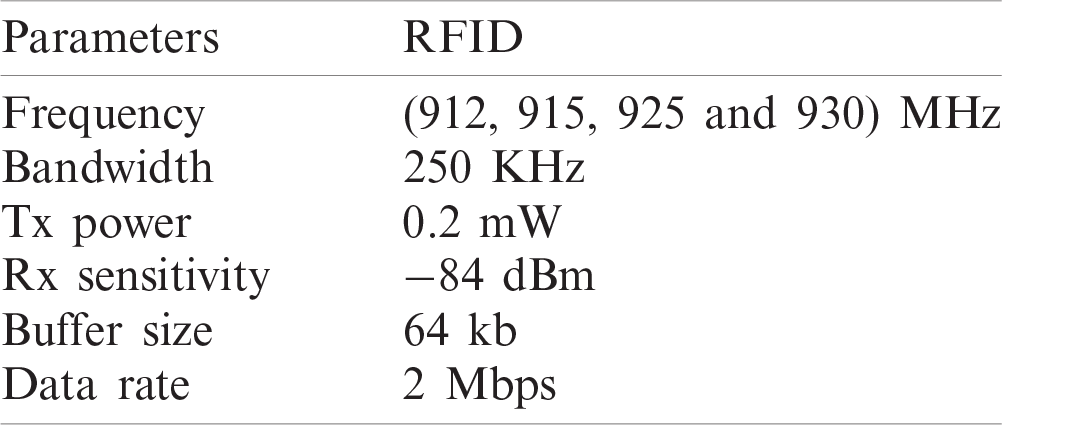

Figure 4: Traffic sent, and traffic received for three
Figs. 4–6 show the results of

Figure 5: Data dropped for three scenarios
As shown in the figures, for

Figure 6: Network delay for three scenarios
This section explains our second proposed protocol that can reliably transmit data with minimum power and delay. Also, it reduces the number of collisions while providing scalability and throughput. Our proposed protocol does not require complex hardware or high power. The protocol is based on back-off the transmission of data by RFID tags for a random time. The protocol minimizes the energy consumption by decreasing the number of collisions as compared to the traditional anti-collision Q algorithm that used RFID tags [31]. There are several reasons that make the RFID as a very effective solution for BCI applications, such as low power, low cost, and the ability of its signal to pass the signal through several layers of the brain. Passive RFID is a great solution for medical applications because it operates with less power than other technologies. The technique used in these tags is called backscatter communication, they are powered by electromagnetic coupling. They receive power externally from the reader and send back the reflected signals that contain the data. The RFID tags showed great promise for real time monitoring of fully implantable sensors in human body [29,30,32]. According to the Federal Communication Commission (FCC) of the United States of America, the power transmitted in the ISM band has to be less than 4 W (EIRP), making UHF-RFID as the best fit for BCI applications [28–30]. The reader sends out query commands to initiate the communication. The query commands inform the senders about its availability to read. The RFID tags that are available in the reader’s region may reply to the reader. A collision might occur if more than one tag reply. To avoid collisions, each tag delays its transmission of data for a random time interval. Upon a successful reception of data, the reader sends an ACK. If the reader receives multiple replies, it will send a NACK to the tags that are involved in the collision. Then, the tags will send the data again by following the same procedure. The phases involved in this process are explained in the following sections.
The query command is a broadcast message the reader sends when it is ready to read. Every tag in the range of the reader receives this query command. If the tags have data to send, it starts transmitting the data after a random back-off time. Otherwise, it remains idle. Staying in the idle state helps the tag to save power. The time taken for the query to reach the tag is called the propagation delay.
After receiving the query command, tags prepare themselves for sending the data. The time taken for a tag to send back the reply to the reader is called the system delay of the tag. This time includes any actual system delay and the random back-off time. The random back-off time is uniformly chosen in the interval of [0.1 to 0.5] s. This interval is chosen since BCI applications are time sensitive. The overall delay with and without retransmissions is explained in the next sections.
A successful transmission is defined as the transmission that does not involve any collision. The probability of a successful transmission will be high when the number of tags is low. When two tags receive the query command, they choose a random back-off time uniformly from the interval [0.1, 0.5]. If the two tags choose different times, there will be no collision and the data can be sent to the reader successfully.
5.4 Collision and Re-Transmission
The collision occurs when two or more tags send reply the reader at the same time. The following scenario explains the event in which a collision might occur. Assume that two tags selected the same back-off time. If two tags have data to send, a collision will take place at the reader. In this case, the propagation delay and system delay are expected to be the same. If the reader detects the collision, it will send a NACK and a new query command. The time the reader takes to send a new query after a NACK is called the system delay at the reader side. When the tags receive the new query, they will choose a random back-off time again. If the random time is different, a successful transmission will take place. The above scenario explains the implementation of our proposed protocol with two RFID tags. However, there could be multiple tags implanted in the brain. In our model, a tag with a new packet to transmit delays the transmission for a random time after it receives the query from the reader. The behavior of a single tag is studied using a Markov model [33], and the probability of packet transmission and collision was calculated.
This protocol was simulated using the NS 2 simulator [34,35]. It is a discrete-event network simulator for Internet systems. We have used 10 tags as passive RFID that work on backscatter, we used frequency hop to assign random channel frequency to each tag. The frequency ranges from 900 to 930 MHZ frequency hop. During the simulation, the delay and collisions were calculated. The parameters used in the simulation are shown Tab. 2.
Table 2: Parameters used for protocol simulation
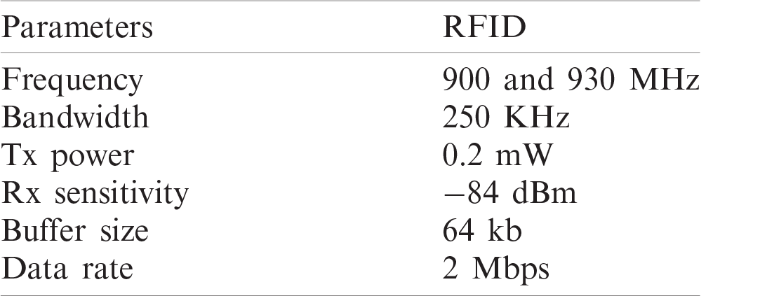
Ten RFID tags were used to analyze the effectiveness of the protocol assuming that the transmitters are implanted in the brain [24]. The transmit power and receive power are kept as low as possible which abides by the FCC recommendations [30,31]. The bandwidth range of the RFID UHF was set from 900 to 930 MHZ [4,24] In our previous tests, we found that the center frequency must be set to 914 MHz. Therefore, we set the frequency of operation to 914 MHz. We used a single reader to analyze the performance of multiple implantable transmitters that are communicating to it. Because of BCI systems were designed to operate without human intervention for long time, the simulation was carried out for a duration of up to 48 h. The following sections explain the evaluation results.
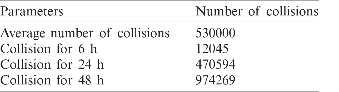
One of the most important factors for BCI applications is collision. The purpose of developing this protocol is to minimize the number of collisions when multiple tags are used inside the brain. The collision is detected at the reader when replies from more than one tag reach the reader at the same time. Tab. 3 shows the average number of collisions that are detected at the reader for a duration of 48 h. The number of collisions detected is calculated as a function of the simulation time in hours. As illustrated in the table, the total number of collisions for the duration of 6 h is 12145 collisions. While the number of collisions for the duration of 48 h is 984269 collisions. The average number of collisions detected is 530000 collisions. The average number of collisions is less than, by 5000, the number of collisions of the Slotted Aloha MAC protocol and 25000 less than the number of collisions of the No MAC protocol [18]. This proved that our proposed protocol enhanced the network performance by reducing the number of collisions.
Table 3: Collision comparison-10 tags
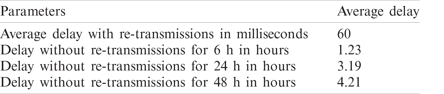
BCI applications are delay sensitive. The total time taken for neuron firing to lead to a muscle activity or a reaction is called the delay. The average time taken by a human to put thoughts into action is about 150 ms [13,18,36]. The auditory and visual reaction time are about 140 to 160 ms and 180 to 200 ms, respectively [18]. Reflex actions are even faster (in the order of micro seconds) as they do not involve the neuron firings [4,18,37–39]. The delay in our protocol can be of two types, which are: delay without retransmissions and delay with retransmissions. Delay without retransmissions is the time taken to receive a successful reply in the first attempt itself, it is involved in a successful transmission. While the delay with retransmissions is the total time taken by for the reader to read a successful reply from a tag after several attempts. Hence, this delay includes the time taken to send a NACK, and the systems delays of the tag and the reader. As shown in Tab. 4, the average delay with retransmission is higher than the delay without retransmission. It is more likely to have several inventories rounds before reading a selected tag [28]. The proposed algorithm does not have multiple command exchanges which decreases the delay and overhead. As shown in the table, the average delay with retransmission is 60 ms, which is 9 ms less than the delay time of the Slotted Aloha protocol and 17 ms less as compared to the No MAC protocol. The delay time of the Slotted Aloha protocol is 69 ms, and the delay of the No MAC algorithm is 77 ms [18]. This proved that our proposed protocol enhanced the network performance by reducing the delay time.
Table 4: Delay comparison-10 tags
BCI applications are designed to allow people with disabilities to communicate with external devices. This takes place by analyzing and translating the brain signals (e.g., ECoG and EEG) to generate useful commands to control the external devices. BCI applications use implanted sensors inside the skull to read the brain signals. These sensors communicate in a wireless manner with external readers to send and receive signals. This paper proposed two MAC protocols that improve the communication between the implanted RFID sensors and the external readers. The first protocol combined the functionalities of CSMA, TDMA, and the FDMA to improve the performance of the network. The first protocol was designed for the EEG signals, it was simulated using the OPNET simulator. The second protocol was designed for the ECoG signals, it was simulated using the NS 2 simulator. The evaluation results showed that both protocols have improved the performance of the brain network and they are suitable for BCI applications. Our future work includes investigating the use of different sensing devices (e.g., WUB) and test our proposed algorithms with more sensors than the sensors we used in this work.
Acknowledgement: We would like to thank our colleagues who supported us during this work.
Funding Statement: The authors received no specific funding for this study.
Conflicts of Interest: The authors declare that they have no conflicts of interest to report regarding the present study.
1. Y. Cui, S. Zhao, H. Wang, L. Xie, Y. Chen et al., “Identifying brain networks at multiple time scales via deep recurrent neural network,” IEEE Journal of Biomedical and Health Informatics, vol. 23, no. 6, pp. 2515–2525, 2018. [Google Scholar]
2. M. A. Ameen, N. Ullah, M. S. Chowdhury, S. R. Islam and K. Kwak, “A power efficient mac protocol for wireless body area networks,” EURASIP Journal on Wireless Communications and Networking, vol. 2012, no. 1, pp. 23–33, 2012. [Google Scholar]
3. S. Katsigiannis and N. Ramzan, “Dreamer: A database for emotion recognition through EEG and ECG signals from wireless low-cost off-the-shelf devices,” IEEE Journal of Biomedical and Health Informatics, vol. 22, no. 1, pp. 98–107, 2017. [Google Scholar]
4. E. F. Hodkin, Y. Lei, J. Humby, I. S. Glover, S. Choudhury et al., “Automated fees for upper limb rehabilitation following stroke and spinal cord injury,” IEEE Transactions on Neural Systems and Rehabilitation Engineering, vol. 26, no. 5, pp. 1067–1074, 2018. [Google Scholar]
5. N. Tiwari, D. R. Edla, S. Dodia and A. Bablani, “Brain computer interface: A comprehensive survey,” Biologically Inspired Cognitive Architectures, vol. 26, no. 3, pp. 118–129, 2018. [Google Scholar]
6. M. Ahn, M. Lee, J. Choi and S. C. Jun, “A review of brain-computer interface games and an opinion survey from researchers,” Sensors, vol. 14, no. 8, pp. 14601–14633, 2014. [Google Scholar]
7. C. Mühl, B. Allison, A. Nijholt and G. Chanel, “A survey of affective brain computer interfaces: Principles, state-of-the-art, and challenges,” Brain-Computer Interfaces, vol. 1, no. 2, pp. 66–84, 2014. [Google Scholar]
8. T. Lefurge, E. Goodall, K. Horch, L. Stensaas and A. Schoenberg, “Chronically implanted intrafascicular recording electrodes,” Annals of Biomedical Engineering, vol. 19, no. 2, pp. 197–207, 1991. [Google Scholar]
9. Y. Zhang and G. Dolmans, “A new priority-guaranteed mac protocol for emerging body area Networks,” in Fifth Int. Conf. on Wireless and Mobile Communications, New York, US, IEEE, pp. 140–145, 2009. [Google Scholar]
10. K. Finkenzeller, RFID Handbook: Fundamentals and Applications in Contactless Smart Cards, Radio Frequency Identification and Near-Field Communication, Hoboken, New Jersey, United States: John Wiley & Sons, 2010. [Google Scholar]
11. D. Seo, H. Y. Tang, J. M. Carmena, J. M. Rabaey, E. Alon et al., “Ultrasonic beamforming system for interrogating multiple implantable sensors,” 37th Annual Int. Conf. of the IEEE Engineering in Medicine and Biology Society, IEEE, vol. 24, pp. 2673–2676, 2015. [Google Scholar]
12. S. Ullah, H. Higgins, B. Shen and K. S. Kwak, “On the implant communication and mac protocols for wban,” International Journal of Communication Systems, vol. 23, no. 8, pp. 982–999, 2010. [Google Scholar]
13. J. L. A. Kumar, M. Sarkar, S. Mohanty and S. H. Ahmed, “A comparative study of mac protocols in brain-computer interface (BCI) applications,” in 2017 13th Int. Wireless Communications and Mobile Computing Conf., IEEE, pp. 1522–1527, 2017. [Google Scholar]
14. R. C. Santiago, K. S. Pour, A. Khaleghi, K. Takizawa, J. Wang et al., “Propagation models for IEEE 802.15.6 standardization of implant communication in body area networks,” IEEE Communications Magazine, vol. 51, no. 8, pp. 80–87, 2013. [Google Scholar]
15. D. Mills, RFC1305: Network Time Protocol (Version 3) Specification, Implementation. RFC Editor, 1992. [Google Scholar]
16. P. Park, P. Di Marco, C. Fischione and K. H. Johansson, “Modeling and optimization of the IEEE 802.15.4 protocol for reliable and timely communications,” IEEE Transactions on Parallel and Distributed Systems, vol. 24, no. 3, pp. 550–564, 2012. [Google Scholar]
17. V. B. Mišić and J. Mišić, “A polling mac for wireless sensor networks with RF recharging of sensor nodes,” in 2014 27th Biennial Symp. on Communications, IEEE, pp. 76–80, 2014. [Google Scholar]
18. H. Harikrishnan, A. Sarkar, C. Paolini and A. Mihovska, “Design and evaluation of a novel mac protocol for multi-implantable UHF-RFID transmitters in brain computer interface applications,” in 2019 Wireless Telecommunications Symp., IEEE, pp. 1–7, 2019. [Google Scholar]
19. A. Tzamaloukas and J. J. Garcia-Luna-Aceves, “A receiver-initiated collision-avoidance protocol for multi-channel networks,” Proc. IEEE INFOCOM, 2001 Conf. on Computer Communications. Twentieth Annual Joint Conf. of the IEEE Computer and Communications Society (Cat. No. 01CH37213), vol. 1, pp. 189–198, 2001. [Google Scholar]
20. S. Ganeriwal, R. Kumar and M. B. Srivastava, “Timing-sync protocol for sensor networks,” Proc. of the 1st Int. Conf. on Embedded Networked Sensor Systems, vol. 25, pp. 138–149, 2003. [Google Scholar]
21. J. Elson, L. Girod and D. Estrin, “Fine-grained network time synchronization using reference broadcasts,” ACM SIGOPS Operating Systems Review, vol. 36, no. SI, pp. 147–163, 2002. [Google Scholar]
22. M. Maróti, B. Kusy, G. Simon and A. Lédeczi, “The flooding time synchronization protocol,” in Proc. of the 2nd Int. Conf. on Embedded Networked Sensor Systems, pp. 39–49, 2004. [Google Scholar]
23. J. Zhao and R. Govindan, “Understanding packet delivery performance in dense wireless sensor networks,” in Proc. of the 1st Int. Conf. on Embedded Networked Sensor Systems, pp. 1–13, 2003. [Google Scholar]
24. A. Jackson, C. T. Moritz, J. Mavoori, T. H. Lucas and E. E. Fetz, “The neurochip bci: Towards a neural prosthesis for upper limb function,” IEEE Transactions on Neural Systems and Rehabilitation Engineering, vol. 14, no. 2, pp. 187–190, 2006. [Google Scholar]
25. H. Balakrishnan, C. L. Barrett, V. A. Kumar, M. V. Marathe and S. Thite, “The distance-2 matching problem and its relationship to the mac-layer capacity of ad hoc wireless networks,” IEEE Journal on Selected Areas in Communications, vol. 22, no. 6, pp. 1069–1079, 2004. [Google Scholar]
26. X. Chang, “Network simulations with opnet,” WSC’99 Winter Simulation Conf. Proc. Simulation-A Bridge to the Future (Cat. No. 99CH37038), vol. 1, pp. 307–314, 1999. [Google Scholar]
27. A. S. Sethi and V. Y. Hnatyshin, The Practical OPNET User Guide for Computer Network Simulation, Boca Raton, Florida, United States: CRC Press, 2012. [Google Scholar]
28. W. T. Chen and W. B. Kao, “A novel q-algorithm for epcglobal class-1 generation-2 anti-collision protocol, World Academy of Science,” Engineering and Technology, vol. 78, pp. 801–804, 2011. [Google Scholar]
29. P. V. Patel, M. Sarkar, S. Nagaraj and K. Kushalad, “Channel modelling based on statistical analysis for brain-computer-interface (BCI) applications,” 2016 IEEE Conf. on Computer Communications Workshops, IEEE, vol. 26, pp. 320–321, 2016. [Google Scholar]
30. S. Al Ajrawi, S. Mohanty, M. Sarkar, R. Rao, A. Mihovska et al., Investigating Feasibility of Multiple UHF Passive RFID Transmitters using Backscatter Modulation, Bellevue, WA: SSMC, pp. 552–563, 2017. [Google Scholar]
31. S. Al Ajrawi, H. Bialek, M. Sarkar, R. Rao and S. H. Ahmed, “Bi-directional channel modeling for implantable UHF-RFID transceivers in brain-computer interface applications,” Future Generation Computer Systems, vol. 88, no. 6, pp. 683–692, 2018. [Google Scholar]
32. D. Seo, R. M. Neely, K. Shen, U. Singhal, E. Alon et al., “Wireless recording in the peripheral nervous system with ultrasonic neural dust,” Neuron, vol. 91, no. 3, pp. 529–539, 2016. [Google Scholar]
33. G. Bianchi, “Performance analysis of the IEEE 802.11 distributed coordination function,” IEEE Journal on Selected Areas in Communications, vol. 18, no. 3, pp. 535–547, 2000. [Google Scholar]
34. T. Issariyakul and E. Hossain, “Introduction to network simulator 2 (ns2),” in Introduction to Network Simulator NS2, Berlin, Germany: Springer, pp. 1–18, 2009. [Google Scholar]
35. J. Chen, C. C.Wang, F. C. D. Tsai, C. W. Chang, S. S. Liu et al., “The design and implementation of wimax module for ns-2 simulator,” in Proc. from the 2006 Workshop on NS-2: The IP Network Simulator ACM, 2006. [Google Scholar]
36. R. Patel, P. Patel, J. Lalwani, M. Sarkar and S. Nagaraj, “Investigating the feasibility of multiple uwb transmitters in brain computer interface (BCI) applications,” in 2016 IEEE 13th Int. Conf. on Wearable and Implantable Body Sensor Networks (BSNIEEE, pp. 236–241, 2016. [Google Scholar]
37. J. Andreu-Perez, D. R. Leff, H. M. Ip and G. Z. Yang, “From wearable sensors to smart implants—Toward pervasive and personalized healthcare,” IEEE Transactions on Biomedical Engineering, vol. 62, no. 12, pp. 2750–2762, 2015. [Google Scholar]
38. R. Muller, H. P. Le, W. Li, P. Ledochowitsch, S. Gambini et al., “A minimally invasive 64-channel wireless ECOG implant,” IEEE Journal of Solid-State Circuits, vol. 50, no. 1, pp. 344–359, 2014. [Google Scholar]
39. J. M. Antelis, L. Montesano, A. Ramos-Murguialday, N. Birbaumer and J. Minguez, “Decoding upper limb movement attempt from EEG measurements of the contralesional motor cortex in chronic stroke patients,” IEEE Transactions on Biomedical Engineering, vol. 64, no. 1, pp. 99–111, 2016. [Google Scholar]
 | This work is licensed under a Creative Commons Attribution 4.0 International License, which permits unrestricted use, distribution, and reproduction in any medium, provided the original work is properly cited. |