DOI:10.32604/cmc.2021.017624
| Computers, Materials & Continua DOI:10.32604/cmc.2021.017624 | |
| Article |
Speed Control of Motor Based on Improved Glowworm Swarm Optimization
1School of Information Science and Engineering, Hebei University of Science and Technology, Shijiazhuang, 050018, China
2School of Internet of Things and Software Technology, Wuxi Vocational College of Science and Technology, Wuxi, 214028, China
3German-Russian Institute of Advanced Technologies, Karan, 420126, Russia
*Corresponding Author: Pingping Yu. Email: yppflx@aliyun.com
Received: 05 February 2021; Accepted: 02 April 2021
Abstract: To better regulate the speed of brushless DC motors, an improved algorithm based on the original Glowworm Swarm Optimization is proposed. The proposed algorithm solves the problems of poor robustness, slow convergence, and low accuracy exhibited by traditional PID controllers. When selecting the glowworm neighborhood set, an optimization scheme based on the growth and competition behavior of weeds is applied to a single glowworm to prevent falling into a local optimal solution. After the glowworm’s position is updated, the league selection operator is introduced to search for the global optimal solution. Combining the local search ability of the invasive weed optimization with the global search ability of the league selection operator enhances the robustness of the algorithm and also accelerates the convergence speed of the algorithm. The mathematical model of the brushless DC motor is established, the PID parameters are tuned and optimized using improved Glowworm Swarm Optimization algorithm, and the speed of the brushless DC motor is adjusted. In a Simulink environment, a double closed-loop speed control model was established to simulate the speed control of a brushless DC motor, and this simulation was compared with a traditional PID control. The simulation results show that the model based on the improved Glowworm Swarm Optimization algorithm has good robustness and a steady-state response speed for motor speed control.
Keywords: PID speed control; improved Glowworm Swarm Optimization; brushless DC motor
With the advancement of Internet of Things (IoT) technology, new motor manufacturing technology has been rapidly developed, and power electronics technology has also entered a new stage of rapid development. In traditional mechanical equipment, the mechanical transmission links in a motor can lead to a series of problems, such as friction, motion lag, vibration and noise. Therefore, electromechanical equipment is being developed towards energy savings, high efficiency and intelligence [1]. As a new type of motor, brushless DC motors have a wide range of control system applications, whether in the field of industrial automation or in smart homes. Intelligent drilling water level detection systems based on IoT technology used in industry, red tide detection systems, sweeping robots used at home, precision IoT-based water and fertilizer management and control systems, and intelligent cloud irrigation systems, all of these applications require motors to drive motion [2]. Brushless DC motors have penetrated into all aspects of people’s lives, and the participation of brushless DC motors in smart home life has been indispensable [3]. Currently, in view of the lack of effective motor monitoring, a monitoring system based on the Internet of things technology has been designed. Serial communication interfaces between devices have been added to facilitate data transmission between devices. If there is a network interface outside the brushless DC motor controller, measurement data and related environmental parameters can be collected from the controller. There data can be sent to a cloud server, to achiever remote monitoring of the brushless DC motor [4]. Currently, many schools connect the controller with Internet to improve students’ ability to analyze and design motors. Information exchange and communication are carried out through a specified network protocol for support hardware-in-the-loop simulations as a teaching platform [5]. At the same time, greater requirements are placed on the control performance of the motor. There are two ways to improve motor control performance. One is to solve the problem by upgrading the hardware. The choice of high-performance hardware will surely improve the performance of the whole system. The second is to improve the speed performance of the motor by changing the control algorithm, which is the focus of this article. Currently, PID controllers are the predominant devices used for motor speed control. With the emergence of intelligent bionic algorithms, at many universities and scientific research institutions, research on PID control algorithms for motors has begun to mostly focus on new algorithms that combine intelligent bionic control algorithms with the PID control. This paper proposes a scheme for controlling a brushless DC motor using a traditional PID controller combined with an existing intelligent control algorithm.
Brushless DC motors are used in the automotive industry, aviation, intelligent robots, high-precision servo motors and other applications due to their small size, light weight, high reliability, simple structure, and high control accuracy [6]. However, brushless DC motors are nonlinear and have a strongly coupled and multivariable structure, making it impossible to achieve the expected speed regulation effect through traditional PID control [7]. Therefore, in recent years, improving the speed regulation performance of brushless DC motors has been a popular topic studied by worldwide scholars. Various intelligent control algorithms have been proposed to optimize brushless DC motors control systems. Zhang [8] used a team competition strategy to develop an improved genetic algorithm. Tuning and optimizing the PID parameters improves the convergence speed and the global optimization, and reduces the overshooting and transition time of the motor in the process of starting, changing load and changing speed. Geng et al. [9] designed a particle swarm optimization algorithm using an orthogonal experiment mechanism for PID parameter tuning to achieve a smaller overshoot and good anti-interference performance. Niasar et al. [10] developed an emotion learning algorithm based on an adaptive neuro-fuzzy inference system (ANFIS) controller, in which a proportional-differential controller function is used to modify the output layer gain of the neuro-fuzzy controller. Kommula et al. [11] proposed a fractional PID control scheme based on the firefly algorithm. In brushless DC motor control, the instantaneous torque of the motor is directly controlled with very low ripple, which improves the efficiency of the motor control torque. Jin et al. [12] combined genetic algorithms with fuzzy control strategies and uniformly encoded membership functions and fuzzy control rule tables for global optimization to improve the robustness of brushless DC motors. Kahveci et al. [13] applied fuzzy control in both the speed and current loops of a brushless DC motor to improve the overall performance of the motor control system. This improved the overall performance of the motor control system. The algorithm designed by Ramesh et al. [14] applied fuzzy logic to predictive control. This simplified the control model identification process, optimized the control effects, and improved the response speed. Taheri et al. [15] used a unified rule table for fuzzy logic to tune the PID parameters in accordance with the system’s error and error rate of change to adapt to different motor control parameter requirements. Xue et al. [16] designed a fuzzy adaptive PID controller. They used a fuzzy control strategy to adaptively adjust the three parameters (
Based on a traditional PID control, this paper improves the traditional Glowworm Swarm Optimization, introduces the invasive weed optimization and the league selection operator, and applies these to the PID speed control system of the brushless DC motor. The PID parameters are adjusted and optimized. The convergence speed and robustness of the algorithm are enhanced.
The remainder of this paper is organized as follows: Section 2 describes the mathematical model of the brushless DC motor, Section 3 introduces the standard Glowworm Swarm Optimization algorithm and the improved algorithm after introducing the invasive weed optimization and Section 4 builds the brushless DC motor using Simulink to simulate the algorithm and analyzes the simulation results. Section 5 summarizes this article.
2 Mathematical Model of Brushless DC Motor
The equivalent circuit diagram of a brushless DC motor control system is shown in Fig. 1.
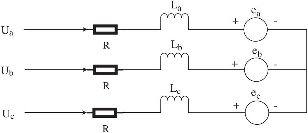
Figure 1: Equivalent circuit diagram of a brushless DC motor
A brushless DC motor is composed of a stator and a rotor. By changing the current, frequency and waveform of the stator winding, the operating state of the rotor can be controlled. The following assumptions can be made when building a mathematical model: ① The three-phase windings are completely symmetrical, and the parameters of each stator winding group are the same. ② The armature winding is evenly and continuously distributed on the inner surface of the stator. ③ The magnetic circuit is not saturated, and eddy current and hysteresis losses are not considered. ④ The cogging, commutation process and armature reaction are ignored [20]. The voltage balance equation can be expressed as
where
Because the three-phase windings are completely symmetrical and the parameters of each group of the stator windings are the same,
According to the working performance of a brushless DC motor, the electromagnetic torque equation can be obtained as
where
The motor motion equation is
where
3 Improved Glowworm Swarm Optimization
3.1 Standard Glowworm Swarm Optimization
The Glowworm Swarm Optimization (GSO) is a bionic swarm intelligent optimization algorithm proposed by Indian scholars Krishnan and Ghose [21,22] in 2005. The algorithm simulates the luminous characteristics of fireflies. The fireflies are scattered in space, and each firefly carries fluorescein and has its own visual range, which represents the decision domain. The fireflies will look for a set of neighbors within the decision domain. The brighter neighbors in the set attract the current firefly to move in that direction. Each time the firefly moves, the direction of the firefly will change with the neighbors selected and with the size of the decision domain. The size of the decision domain is also affected by the number of neighbors. When the neighbor density is lower, the decision domain radius of the firefly will increase to find more neighbors; when the firefly density is higher, a firefly’s decision domain radius will decrease. Allowing the fireflies to gather around the brighter fireflies achieves the optimization. The GSO algorithm includes four primary steps: GSO parameter initialization, fluorescein updating, firefly movement and decision domain updating.
Step One: GSO parameter initialization. Randomly place
Step Two: Fluorescein updating:
where
Step Three: Firefly movement. Find the neighborhood fireflies:
where
Determine the direction of the fireflies:
where
Step Four: Decision domain updating. Update the location of each firefly
where
Update the radius of the dynamic decision domain of each firefly:
where
3.2 Invasive Weed Optimization
The invasive weed optimization is an algorithm proposed by Mehrabian et al. [23–25] to simulate the reproduction of weeds. It shows good robustness and convergence and strong randomness. The invasive weed optimization algorithm simulates the natural processes of seed generation, diffusion, and reproduction of weeds and the survival of the fittest.
Step One: Randomly initialize some weeds in an initial area.
Step Two: During the process of evolution, the weeds produce seeds in proportion to their fitness. The relationship between the adaptive function and the number of weed seeds is the following:
where
The method for determining the number of weed seeds is illustrated in Fig. 2.
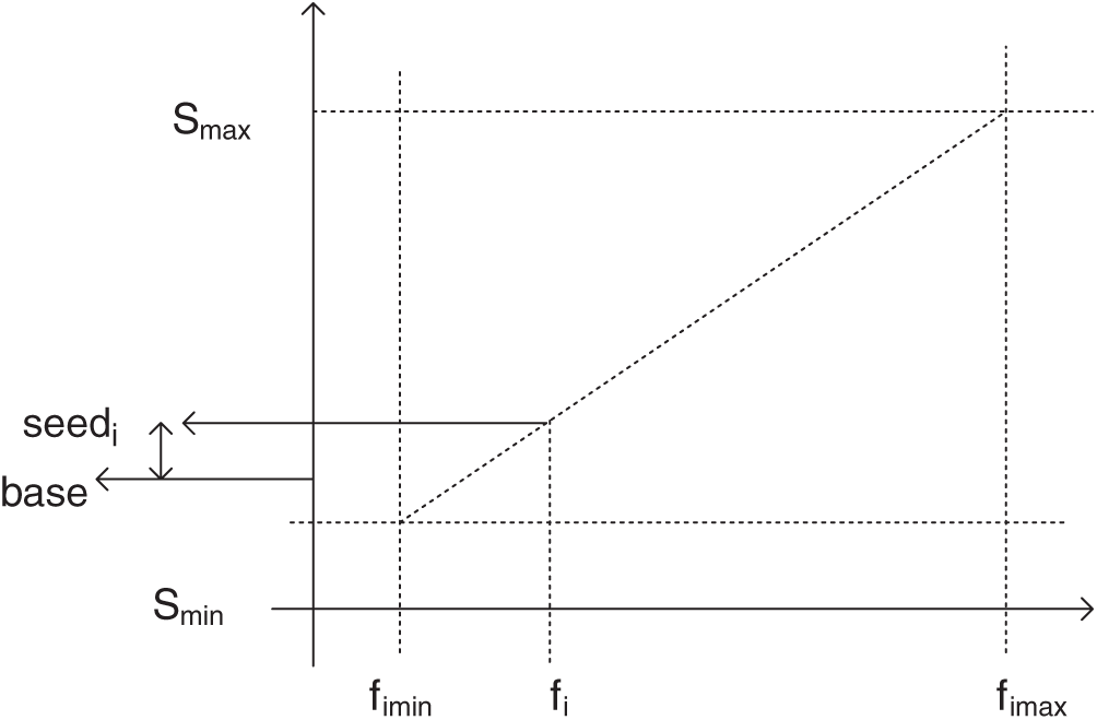
Figure 2: Determine the number of weed seeds
Fig. 2 shows the relationship between the fitness value and the number of weed seeds. The number of seeds is determined by the fitness value. High fitness values produce more seeds, and individuals with low fitness values produce fewer seeds.
Step Three: Randomly generated seeds are scattered around the mother plant in a normal distribution in the search space, and the standard deviation of the normal distribution is also scattered:
where
Step Four: After multiple iterations, the population reaches its maximum value. For plants with poor adaptability, the competitive process will begin, and the fittest will survive. Arrange the mother plants and progeny plants in the order of fitness from large to small, and the remaining plants are eliminated when the population reaches the maximum.
3.3 Improved Glowworm Swarm Optimization
In the GSO, if the area to be optimized is relatively wide, the position of the firefly will be more scattered during initialization, and a single firefly cannot be searched due to insufficient brightness. The existence of multiple independent fireflies in the space will lead to waste of resources. So the operating efficiency of the algorithm will be reduced, and the shortcoming of falling into a local optimization will occur. Coupled with the randomness of the firefly movement, and because the positions of the fireflies are constantly updated, the distance between the movement of bright fireflies and the optimal value cannot be accurate. When controlled, the firefly moves too far to exceed the optimal position. If the step is too small, the number of iterations will increase, which will lead to problems such as slow convergence, poor robustness, and poor accuracy. Therefore, the encroachment, reproduction and competition behavior of weeds are introduced. And the standard deviation
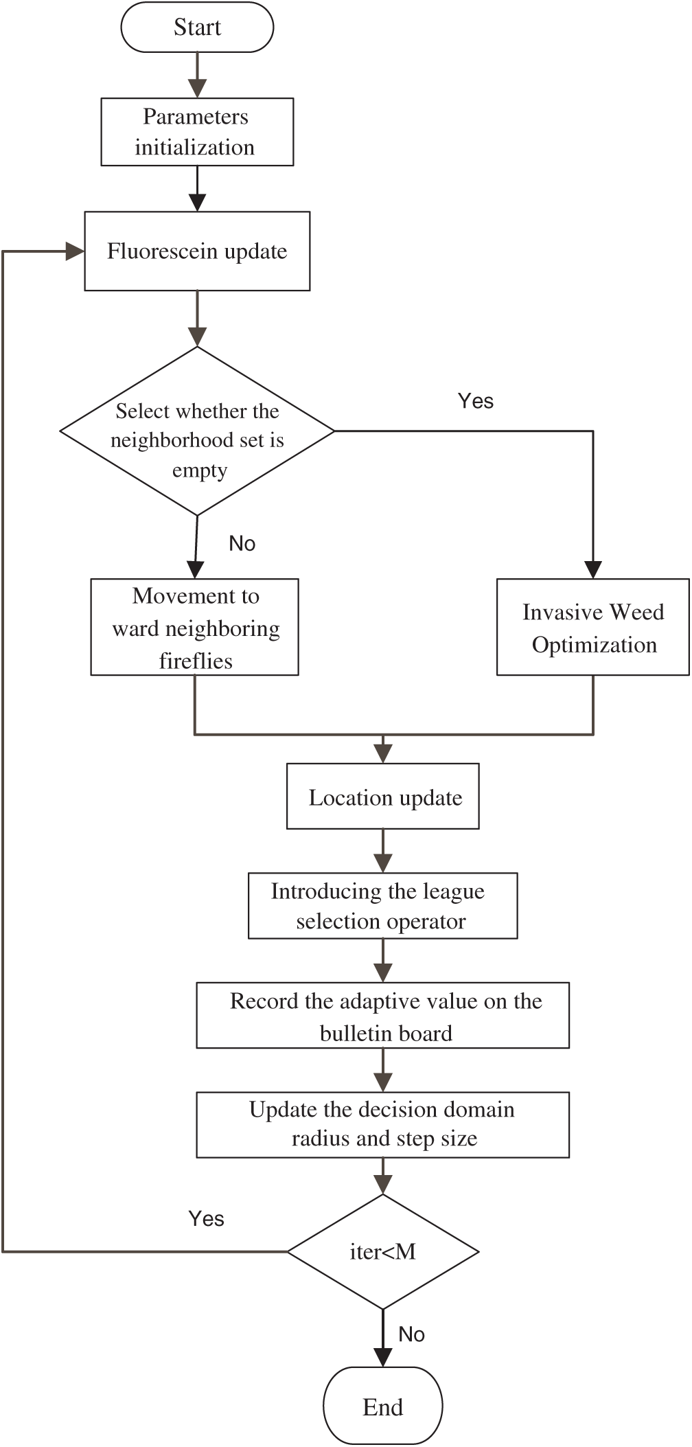
Figure 3: Flow chart of improved GSO
The specific implementation steps are as follows:
Step One: Initialize the population parameters and randomly generate
Step Two: Update and calculate the fluorescein of each firefly: use Eq. (6) to update the fluorescein;
Step Three: Within the sight of the firefly, look for the set
Step Four: Select the neighborhood set, use formula (9) to calculate the probability
Step Five: Introduce the preemptive reproduction behavior and the survival of the fittest competition behavior in the invasive weed optimization into the firefly, and reproduce the offspring of a single firefly. According to formula (12), the “seed” of the firefly
Step Six: Use formula (10) to update the position of each firefly;
Step Seven: Introduce the league selection operator in the genetic algorithm. The league selection operator strategy is: selecting the optimal solution to enter the next iteration. In order to continue the excellent genes in the maternal fireflies, the progeny with poorer fitness values are replaced with the maternal with better fitness values during the generation of the offspring of the maternal firefly through the league selection operator strategy. All individuals are sorted according to the value of the objective function, and a threshold
Step Eight: After sorting, the fish school bulletin board is used to record the position of the optimal individual and the objective function value. After each iteration, the objective function value of each firefly is calculated and compared with the optimal objective function value in the bulletin board. If the objective function is better than the value in the bulletin board, use this instead. If it is lower than the objective function value in the bulletin board, the value in the bulletin board remains unchanged;
Step Nine: Update the firefly’s decision domain radius
Step Ten: Judge whether the number of iterations reaches the maximum number of iterations
4 Simulation of the PID Speed Regulation of a Brushless DC Motor
The principle of PID control is to make adjustment according to the deviation
where
According to the PID calculation formula, the PID control block diagram can be obtained, as shown in Fig. 4.
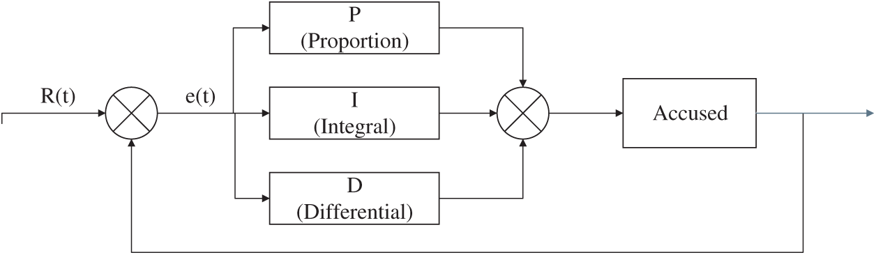
Figure 4: Block diagram of PID control
Simulink model is built according to the PID control [28] block diagram shown in Fig. 5.
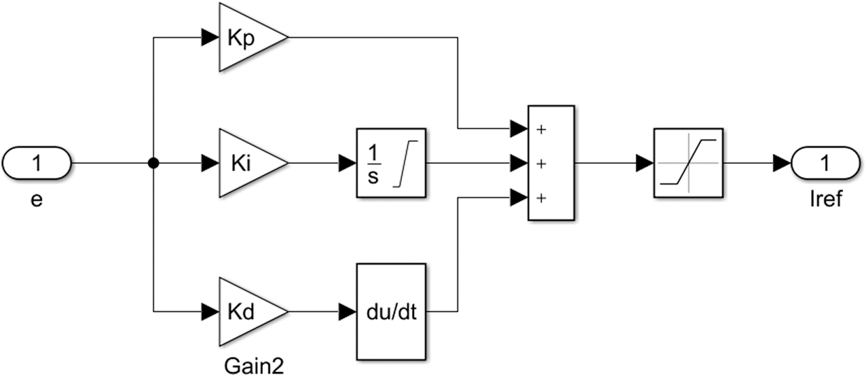
Figure 5: PID simulation model
The brushless DC motor uses three-phase six-states motor. The double closed loop consists of a speed loop and a current loop. The speed loop is the outer loop and the current loop is the inner loop. The model includes a brushless DC motor module, an improved GSO regulation PID module, a current hysteresis loop, a regulation module and a three-phase inverter module. The system block diagram is shown in Fig. 6.
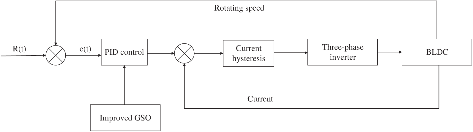
Figure 6: System block diagram of the brushless DC motor
First, we input a rated speed, and set the difference between the feedback value of the loop speed of the brushless DC motor as e(t), and input e(t) to the PID controller. The difference in the speed is calculated by proportional, integral and derivative. The error of the feedback value with the current loop is output, and fed to the brushless DC motor through the current hysteresis loop and the three-phase inverter, so as to control the stable operation of the motor. Adjustment of speed control is very important for brushless DC motors. However, a traditional PID controller has a long adjustment time, and a phenomenon of chattering during the control process which cannot be recovered in time due to large external interference. These make the traditional PID controller difficult to meet the requirements of production. The PID controller optimized by the improved GSO can effectively solve the shortcomings of the motor, such as an extended motor adjustment time, poor robustness, and large overshoot, and make the brushless DC motor run more smoothly and reliably.
According to the mathematical model and system control block diagram of the brushless DC motor, a double closed-loop speed regulation simulation model of the brushless DC motor is built in Simulink and it shown in Fig. 7.
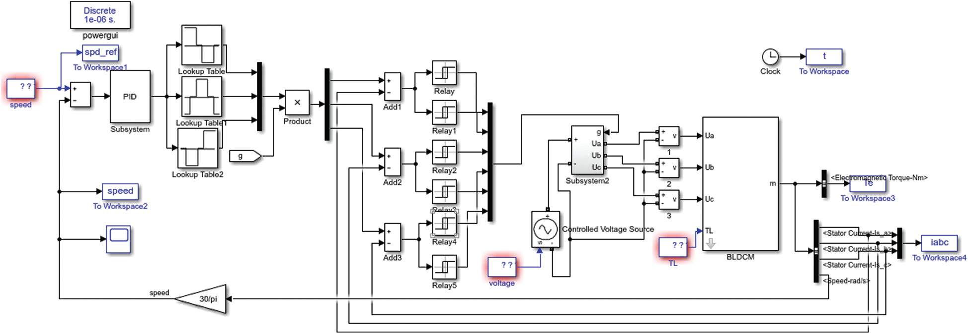
Figure 7: Double closed-loop speed regulation model of the brushless DC motor
The parameters used by the motor are as follows: the back electromotive force coefficient
The transfer function is obtained by substituting the parameters into formula (15).
The initial firefly population is set to 50, and the maximum number of iterations is
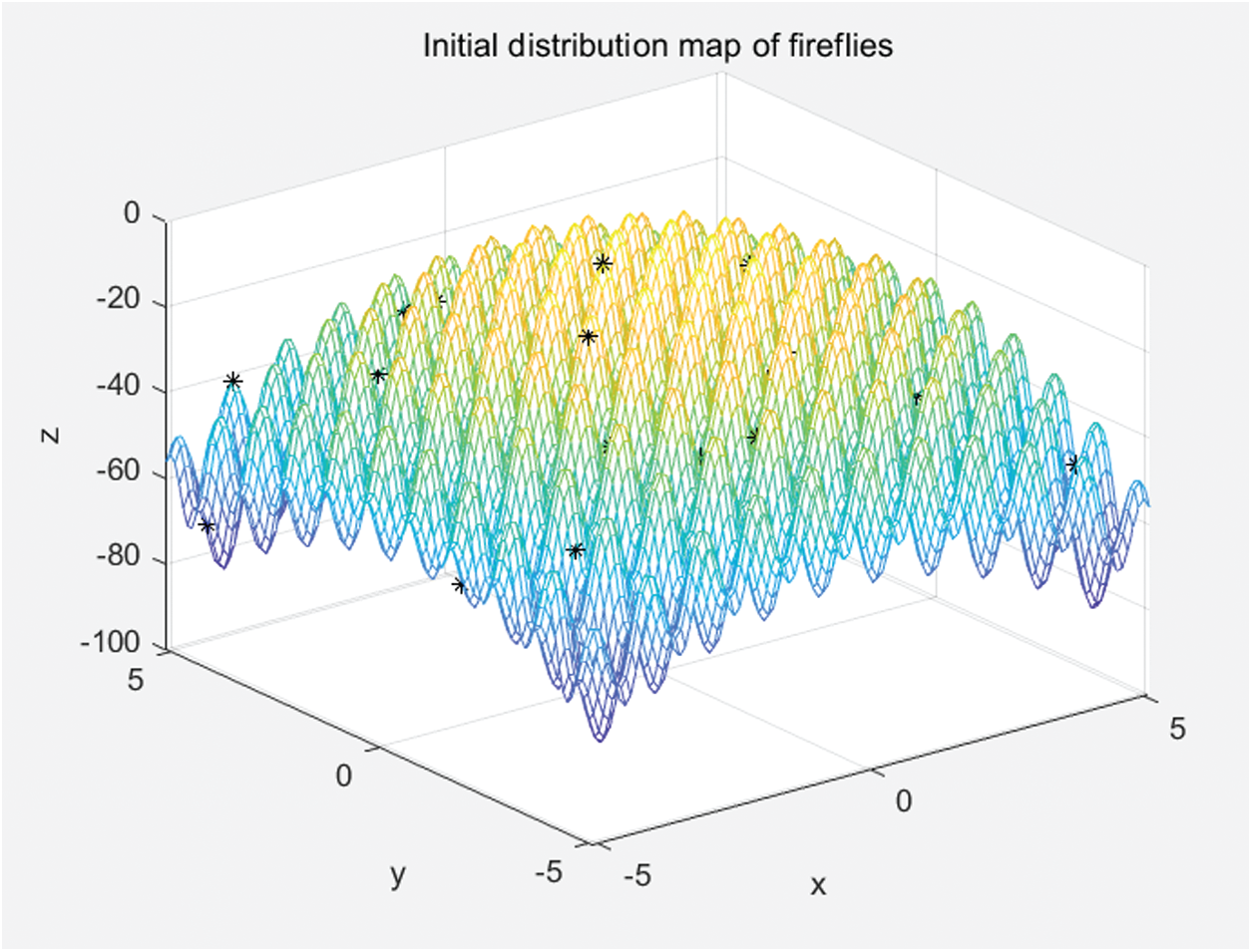
Figure 8: The initial distribution of fireflies
After 200 iterations, the fireflies gather around the brighter fireflies, as shown in Fig. 9. Almost all fireflies congregate at the four extreme points below.
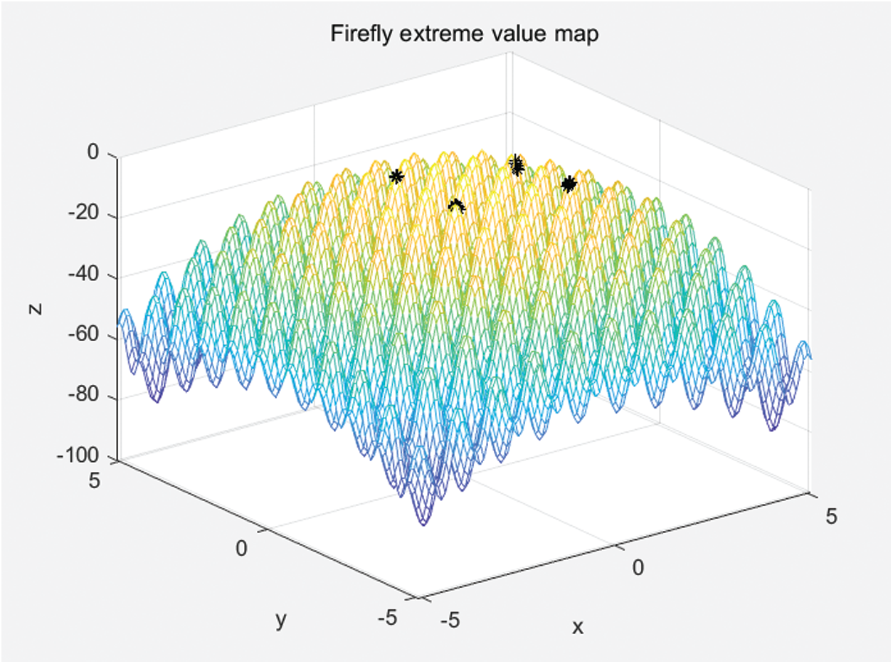
Figure 9: Firefly extremum distribution map
After 200 iterations, the best fitness value is obtained, as shown in Fig. 10.
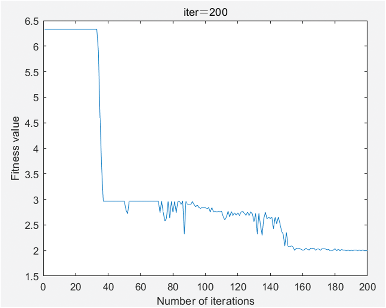
Figure 10: Evolution of fitness over 200 iterations
The initial speed is set to 1,450 rpm. The simulation model is built by using the transfer function of the brushless DC motor. The improved GSO is applied to the PID control to compare with the conventional PID algorithm and compare the waveform. The motor is started to the input rated speed under the two algorithms. Their waveforms are shown in Figs. 11 and 12.
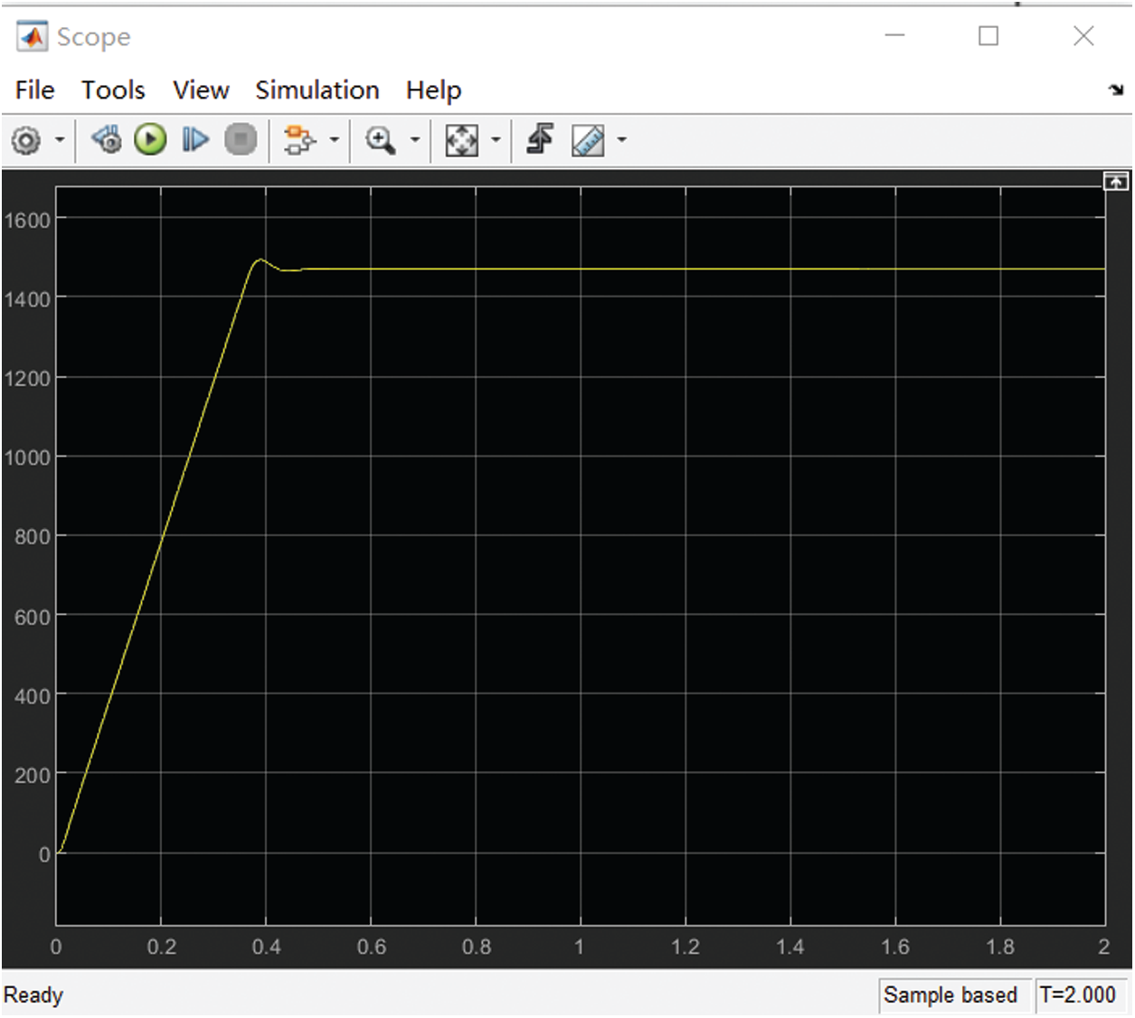
Figure 11: Waveform of traditional PID algorithm
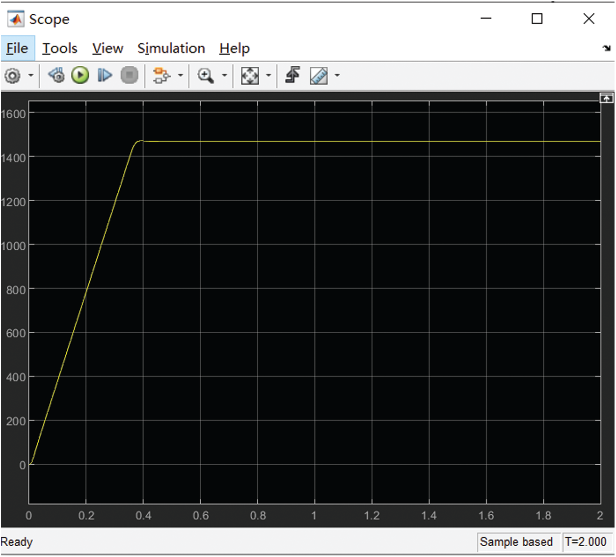
Figure 12: Waveform of improved PID control algorithm
Though waveform comparison, it can be seen that the PID control with improved GSO has almost no overshoot before the motor starts to reach the rated speed, while the traditional PID control has a higher overshoot. The improved GSO has reached a stable state at 0.4 s, while the traditional PID algorithm reaches a stable state at about 0.5 s.
The current-time diagrams for both algorithms are shown in Figs. 13 and 14.
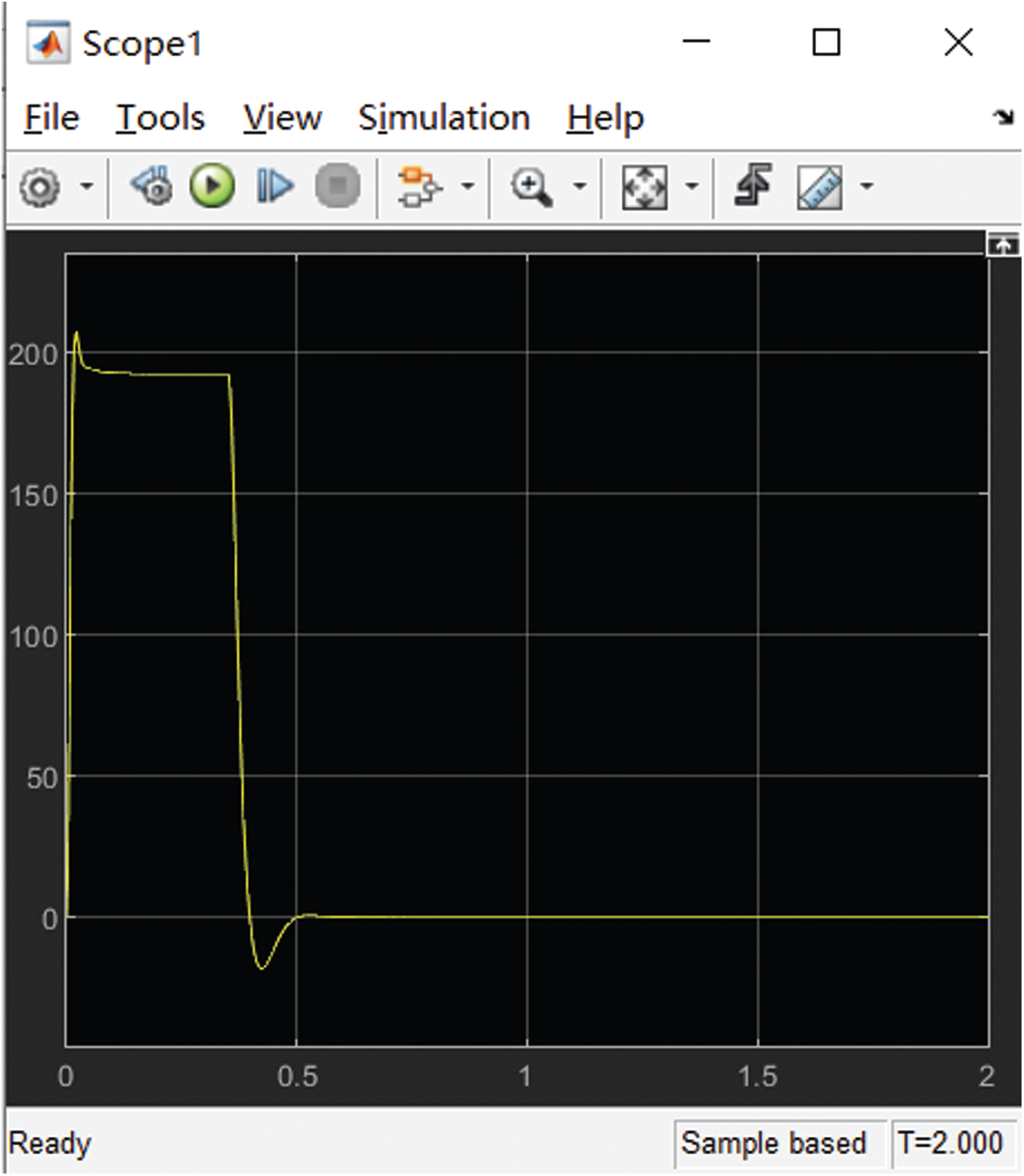
Figure 13: The current waveform of the traditional PID algorithm
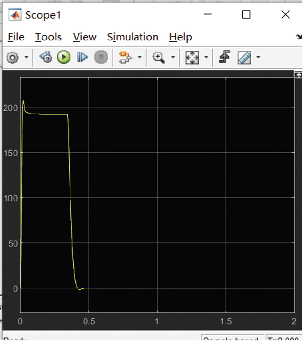
Figure 14: The current waveform of the improved algorithm
It can be seen from the figures that the current fluctuation of the traditional PID is relatively large at 0.4 s, while the improved algorithm has almost no current fluctuation at 0.4 s, and the overshoot is small.
This paper proposes an improved GSO to be applied to the PID speed control system of a brushless DC motor, which combines the improved GSO with traditional PID control for the speed control of a brushless DC motor. A dual closed-loop control simulation model of a brushless DC motor was built in Simulink to simulate the application of the improved GSO to motor speed control. The simulation results show that the improved GSO overcomes the slow convergence speed and poor robustness of the standard GSO. The speed response of the brushless DC motor is accelerated, the robustness is enhanced, and the accuracy of the algorithm is improved. This approach provides a new reference idea for optimizing motor control systems.
Acknowledgement: We acknowledge funding from the Hebei Science and Technology Support Project (19273703D) and the Hebei Provincial Higher Education Science and Technology Research Project (ZD2020318).
Funding Statement: This research was funded by the Hebei Science and Technology Support Program Project (19273703D), and the Hebei Higher Education Science and Technology Research Project (ZD2020318).
Conflicts of Interest: The authors declare that they have no conflicts of interest to report regarding the present study.
1. S. D. Zhao and X. Jia, “Research progress and trend of intelligent manufacturing and its core information equipment,” Mechanical Science and Technology, vol. 36, no. 1, pp. 1–16, 2017. [Google Scholar]
2. J. Ding, M. S. Wang, D. G. Li, B. Wang and J. R. Zhu, “Design of multi-motor monitoring system based on internet of things technology,” Modern Electronic Technology, vol. 38, no. 15, pp. 136–138, 2015. [Google Scholar]
3. H. Zhao, D. R. Zhao, P. Luo, C. Guo, J. Zhang et al., “Research on fuzzy adaptive control system of brushless DC motor,” Micro-motor, vol. 53, no. 1, pp. 72–78, 2020. [Google Scholar]
4. C. Cui, G. Liu and K. Wang, “A novel drive method for high-speed brushless DC motor operating in a wide range,” IEEE Transactions on Power Electronics, vol. 30, no. 9, pp. 4998–5008, 2015. [Google Scholar]
5. X. H. Zhou, Y. Zhang, H. L. Lan, C. Wang and G. Q. Wu, “Design of virtual experiment platform for brushless DC motor closed-loop speed regulation system,” Laboratory Research and Exploration, vol. 39, no. 1, pp. 98–102, 2020. [Google Scholar]
6. H. Q. Yin, W. J. Yi, C. C. Li and H. Z. Meng, “Research on control system of missile-borne brushless DC motor based on speed loop fuzzy parameter adaptive PID algorithm,” Acta Armamentariums, vol. 41, no. S1, pp. 30–38, 2020. [Google Scholar]
7. G. D. Zhang and R. M. Qi, “Design and simulation of fuzzy PID control system of brushless DC motor,” Coal Mining Machinery, vol. 39, no. 1, pp. 13–15, 2018. [Google Scholar]
8. Y. X. Zhang, “Optimal control simulation of brushless DC motor speed regulation performance,” Computer Simulation, vol. 33, no. 11, pp. 395–399, 2016. [Google Scholar]
9. W. B. Geng and Z. A. Zhou, “Research on BLDCM speed regulation system optimized by improved particle swarm algorithm,” Control Engineering, vol. 26, no. 9, pp. 1636–1641, 2019. [Google Scholar]
10. A. M. Niasar, A. Vahedi and H. Moghbelli, “Speed control of a brushless DC motor drive via adaptive neuro-fuzzy controller based on emotional learning algorithm,” in 2005 Int. Conf. on Electrical Machines and Systems, Nanjing, pp. 230–234, 2005. [Google Scholar]
11. B. N. Kommula and V. R. Kota, “Direct instantaneous torque control of brushless DC motor using firefly algorithm based fractional order PID controller,” Journal of King Saud University—Engineering Sciences, vol. 32, no. 2, pp. 133–140, 2020. [Google Scholar]
12. P. Jin and J. Li, “BLDC fuzzy PID control system based on improved genetic algorithm,” Automation and Instrumentation, pp. 14–15, 2015. [Google Scholar]
13. H. Kahveci, H. I. Okumus and M. Ekici, “Improved brushless DC motor speed controller with digital signal processor,” Electronics Letters, vol. 50, no. 12, pp. 864–866, 2014. [Google Scholar]
14. M. V. Ramesh, J. Amarnath and S. Kamakshaiah, “Speed control of brushless DC motor by using fuzzy logic PI controller,” ARPN Journal of Engineering and Applied Science, vol. 6, no. 9, pp. 55–62, 2011. [Google Scholar]
15. S. Y. Taheri, J. Lin, J. S. Yuan and M. Bassiouni, “Security interrogation and defense for SAR analog to digital converter,” Electronics, vol. 6, no. 2, pp. 48, 2017. [Google Scholar]
16. D. Xue, L. Liu and F. Pan, “Variable-order fuzzy fractional PID controllers for networked control systems,” in 2015 IEEE 10th Conf. on Industrial Electronics and Applications, Auckland, New Zealand. IEEE, pp. 1438–1442, 2015. [Google Scholar]
17. A. Ramya, A. Imthiaz and M. Balaji, “Hybrid self tuned fuzzy PID controller for speed control of brushless DC motor,” Auto Matika, vol. 57, no. 3, pp. 672–679, 2016. [Google Scholar]
18. M. Yang and X. C. Wang, “Fuzzy PID controller using adaptive weighted PSO for permanent magnet synchronous motor drives,” in 2009 Second International Conf. on Intelligent Computation Technology and Automation, Washington DC, USA. IEEE, pp. 736–739, 2009. [Google Scholar]
19. H. L. Lin, K. Y. Song, B. L. Dong and H. Fang, “Brushless DC motor control method based on particle swarm neural network,” Power Electronics Technology, vol. 53, no. 12, pp. 106–110, 2019. [Google Scholar]
20. G. Y. Wang, Z. G. Huang and M. Dai, “Research on fuzzy control of brushless motor based on improved particle swarm algorithm,” Journal of Guangxi Normal University, vol. 34, no. 2, pp. 21–27, 2016. [Google Scholar]
21. L. W. Chen, “Research on optimization method of PID parameters based on firefly algorithm,” Modern Electronic Technology, vol. 38, no. 18, pp. 5–7, 2015. [Google Scholar]
22. Y. L. Li, M. Dong, C. M. Ye and Q. M. Liu, “Glowworm swarm optimization and simulation application with weed behavior,” Journal of System Management, vol. 24, no. 4, pp. 496–503, 2015. [Google Scholar]
23. W. A. Qasim and B. A. Mitras, “A suggestion algorithm instituted on invasive weed optimization algorithm and bat optimization algorithm,” Open Access Library Journal, vol. 7, no. 6, pp. 1–11, 2020. [Google Scholar]
24. E. M. Abdelkader, O. Moselhi, M. Marzouk and T. Zayed, “A multi-objective invasive weed optimization method for segmentation of distress images,” Intelligent Automation & Soft Computing, vol. 26, no. 4, pp. 643–661, 2020. [Google Scholar]
25. T. Chen and M. Yeh, “Optimized PID controller using adaptive differential evolution with meanof-pbest mutation strategy,” Intelligent Automation & Soft Computing, vol. 26, no. 3, pp. 407–420, 2020. [Google Scholar]
26. Y. Liu, X. Yan, F. Yan, Z. Xu and W. Shang, “Sliding-mode PID control of UAV based on particle swarm parameter tuning,” Computers, Materials & Continua, vol. 63, no. 1, pp. 469–487, 2020. [Google Scholar]
27. P. Chen and G. Chen, “The design of a tld and fuzzy-pid controller based on the autonomous tracking system for quadrotor drones,” Intelligent Automation & Soft Computing, vol. 26, no. 3, pp. 489–500, 2020. [Google Scholar]
28. J. Ye, “PID tuning method using single-valued neutrosophic cosine measure and genetic algorithm,” Intelligent Automation & Soft Computing, vol. 25, no. 1, pp. 15–23, 2019. [Google Scholar]
 | This work is licensed under a Creative Commons Attribution 4.0 International License, which permits unrestricted use, distribution, and reproduction in any medium, provided the original work is properly cited. |