DOI:10.32604/cmc.2021.017666
| Computers, Materials & Continua DOI:10.32604/cmc.2021.017666 | |
| Article |
PAPR Reduction in NOMA by Using Hybrid Algorithms
Department of Electronics and Communication Engineering, JECRC University, Jaipur, 303905, India
*Corresponding Author: Arun Kumar. Email: arun.kumar1986@live.com
Received: 06 February 2021; Accepted: 02 April 2021
Abstract: Non-orthogonal multiple access (NOMA) is gaining considerable attention due to its features, such as low out-of-band radiation, signal detection capability, high spectrum gain, fast data rate, and massive D2D connectivity. It may be considered for 5G networks. However, the high peak-to-average power ratio (PAPR) is viewed as a significant disadvantage of a NOMA waveform, and it weakens the quality of signals and the throughput of the scheme. In this article, we introduce a modified NOMA system by employing a block of wavelet transform, an alternative to FFT (Fast Fourier transform). The modified system combines the details of fractional frequency and time analysis of NOMA signals. In this correspondence, we utilize an advanced partial transmission scheme (PTS), and selective mapping (SLM), and present a genetic algorithm (GA) for SLM to investigate the peak power performance of a WT-based NOMA system. The performance of WT-SLM, WT-PTS, and WT-SLM-GA methods is compared with that of the traditional NOMA-based SLM and PTS methods. The simulation results demonstrate that the proposed system effectively reduces PAPR in comparison with the traditional schemes.
Keywords: PAPR; wavelet transform; NOMA; PTS; SLM; 5G
With the increase in the numbers of devices, subscribers, demands, and services, data traffic is assumed to increase by a thousand times [1]. Presently, no techniques can satisfy all requirements. Nevertheless, the forthcoming 5G radio is expected to fill all demands and services. An orthogonal frequency division multiplexing (OFDM) waveform is used in 4G radio, but it is not considered for 5G due to several disadvantages, as investigated in [2]. Therefore, a 5G radio waveform must be explored. Transmission techniques will play a major role in the development of a high-performance and advanced radio system. Over the last few years, several advanced waveform schemes [3] have been proposed for 5G networks [3]. Among them, non-orthogonal multiple access (NOMA) has gained extensive attention due to its efficient spectral efficiency, as discussed in [4]. NOMA is an advanced transmission scheme based on a multicarrier scheme and regarded as one of the strong contenders for 5G cellular communication. It is designed through the superposition coding (SC) and successive interference cancellation (SIC). The function of SC is to transmit NOMA signals to several users and SIC is used to de-multiplex the signals at the receiver. The use of SC will decrease the delay and complexity of the NOMA waveform because no error occurs when transmitting NOMA signals [5]. Nonetheless, the high peak-to-average power ratio (PAPR) is considered a great obstacle in the standardization of the NOMA waveform in 5G systems. Several reduction techniques have been implemented in the OFDM system. However, these reduction techniques cannot be used in NOMA given their different construction and systems [6]. The disadvantage of the NOMA-based OFDM is the degradation of system flow due to excessive peak power. In [7], the authors presented a DST precoding method to enhance the PAPR performance of the NOMA-based OFDM system. The proposed method was compared with the conventional NOMA Walsh–Hadamard transform NOMA. The simulation results showed that the proposed DST performed better than the conventional techniques. The authors also presented a finite impulse filter grounded on the Hadamard technique to overcome the peak power effect. The proposed method was compared with the non-precoded and HT precoded methods. It was effective in reducing the peak power of the waveform [8]. In [9], a modified precoded technique was used to minimize the peak power of the NOMA-based OFDM waveform. Prior knowledge of side information was not needed in the projected method. The simulation results demonstrated that the PAPR and BER of the proposed method were better than those of conventional designs. The authors introduced a PTSCT scheme to minimize the peak power of the NOMA waveform. In this algorithm, partial transmission scheme (PTS) was initially applied to advanced waveforms, which minimized the amplitude power, Circular Transformation (CT) was then applied to decrease the complexity of the organization. The simulation results indicated that PTSCT was better than the conventional PTS [10]. A hybrid method based on a combination of swarm optimization for PTS was proposed for the OFDM waveform. In this method, the best phase variation elements were chosen to reduce the peak power of the signal. The experimental result showed enhanced PAPR performance [11]. The authors also introduced a wavelet transform (WT) block within the MIMO-OFDM structure to overcome the effect of high PAPR. The simulation results showed that the wavelet MIMO-OFDM efficiently reduced PAPR as compared with the traditional OFDM structure [12]. In [13], PTS was used to decrease the amplitude power of the UFMC system. The study indicated a considerable reduction in PAPR, and the complexity of the arrangement was mitigated by the proposed framework. In [14], the P-PTS method was enforced to scale down the amplitude power of a filter bank multicarrier system. An efficient result could be obtained by changing the number of sub-blocks and subcarriers. The experimental outcomes showed that the amplitude power was significantly reduced by the proposed P-PTS compared with other techniques. Nevertheless, the complexity of P-PTS was not discussed in the study. The authors presented a genetic algorithm (GA)-centric PTS technique to minimize the peak power of the OFDM structure. The technique achieved gains of 0.11 and 0.46 dB compared with the traditional PTS [15]. In [16], PTS was proposed to minimize the PAPR and complexity of the OFDM structure. Peak power was reduced by multiplying the PTS sub-blocks by an ideal phase vector, for which a minimal PAPR was obtained. The simulation results showed that a PAPR was reduced to 5.98 dB at the CCDF of 10−3. The selective mapping (SLM) method was presented to reduce the amplitude and average power of the OFDM signal [17]. The conventional SLM increased the system complexity due to the use of large numbers of IFFTs. By contrast, the presented method minimized the complexity by separating the OFDM signal into odd and even signals. The experimental outcomes demonstrated that the proposed SLM achieved optimal performance compared with the other schemes. In [18], the SLM method was introduced to overcome the effect of PAPR in a multicarrier OFDM structure. The proposed method optimized the PAPR performance, with a low power requirement and no loss of side information. A joint optimization method centered on SLM and CT was suggested to reduce the amplitude power of NOMA and FBMC signals. The optimal outcome was achieved in two phases. At the primary stage, OFDM and NOMA signal sub-blocks were generated by applying the SLM scheme. IFFTs were applied to the number of sub-blocks. SLM increased the computational complexity of the structure. CT was then applied to reduce the complexity, and a low PAPR signal was selected for transmitting [19]. From the existing literature, SLM-WT, PTS-WT, and SLM-GA-WT techniques had not been investigated for the NOMA system. In this study, the objective of the proposed method is to replace the IFFT with IDWT of the NOMA structure. Advanced SLM, PTS and SLM-GA methods are also applied to a WT-based NOMA system to evaluate the performance in PAPR.
This study investigates the performance of dynamic NOMA signals in time and frequency domains. WT is identical to Fourier transform (FT). In FT, the function is restrained in the Fourier space. By contrast, WT utilizes the function restricted in the Fourier and real-time span. The abilities to calculate fast and to study sub-details of signals are considered significant benefits of WT. It is utilized to split signals into the elements of a wavelet. Hence, it is feasible to acquire an excellent estimation of the function by utilizing a small number of coefficients, compared with FT. However, high-cost implementation, utilization of massive numbers of WT, distortion in signals, and lengthy compacting time are few of the drawbacks of WT. Mathematically, WT can be expressed as [20]:
where h[k] and g[k] are the characteristics of high and low-pass filters, representing the wavelet and scalar functions;
where
2.2 Estimation of the PAPR of the NOMA Waveform
The schematic of the wavelet-based NOMA waveform is indicated in Fig. 1. In this proposed model, IDWT and DWT blocks are introduced in place of FFT and IFFT. The proposed system allows the access of each subcarrier by all users.

Figure 1: Schematic of NOMA
The NOMA signal is given as:
where
IDWT converts the NOMA signal into a time-domain NOMA signal. A PHYDAS filter is applied to the time-domain NOMA signal, which is given as:
Eq. (8) can be written as:
where T is the period of the NOMA symbol. Traditionally, PAPR is expressed in terms of dB, given as:
The complementary cumulated distribution function (CCDF) is a significant parameter which indicates the effectiveness of reduction methods. Hence, PAPR should be defined in terms of the CCDF of NOMA, as shown as follows:
2.3 Wavelet Transform Based SLM (SLM-WT)
The SLM technique was presented in 1996 [21]. SLM is regarded as one of the most efficient PAPR minimization methods, as shown in Fig. 2. The purpose of the conventional SLM, is to generate an optimal phase vector for the sub-blocks of the NOMA symbol and IFFT are applied to it. A low-PAPR signal is then chosen and transmitted. However, SLM introduces a high computational complication due to the use of IFFTs. In the projected system, the optimal phase factor is multiplied with NOMA symbols, and the IDWT block is used instead of IFFT. The NOMA signal is applied to IDWT, which converts the NOMA signal into a time-domain one. Lastly, a low-peak-power signal is selected and transmitted with low computational complexity.
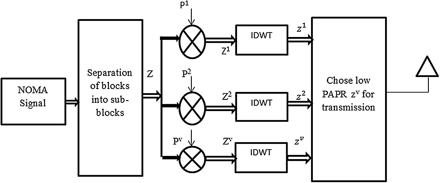
Figure 2: DWT-SLM
The NOMA symbols are divided into several sub-blocks given as:
The phase vector (
where
A low-PAPR NOMA signal is given as:
PAPR is expressed in terms of dB, given as:
From Eq. (22), the proposed SLM-DT method depends on V and N. Thus, varying V and N results in the optimal reduction of PAPR.
2.4 Wavelet Transform Based PTS (PTS-WT)
The PTS method was first implemented in 1997 [22]. In this method, the NOMA symbols are divided into several data blocks applied to IDWT. The data blocks are weighted using a phase element (W) to produce a low-value PAPR signal. The proposed model is shown in Fig. 3.
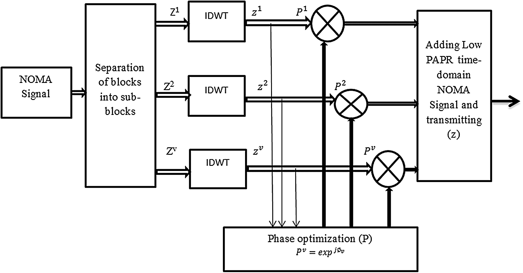
Figure 3: WT-PTS
The NOMA symbols are given as
The sub-blocks are orthogonal to one another. Hence, the NOMA symbol (Z) can be expressed as the addition of entire sub-blocks V, given as:
The phase factor is given as:
A minimum-PAPR NOMA signal is achieved by multiplying Eqs. (25) and (26), as shown as follows:
The phase alteration factor is limited to
PAPR is expressed in terms of dB, given as:
2.5 Wavelet Transform Based SLM-GA (SLM-GA-WT)
We present a hybrid PAPR method grounded in artificial intelligence centered genetic algorithm sustained, SLM sequence denoted as SLM-GA, to reduce the peak power of NOMA. In the hybrid method, peak power minimization is accomplished and complexity is significantly reduced. NOMA signals are divided into different sub-blocks and applied to IDFT converting frequency-domain NOMA sub-blocks in time-domain NOMA sub-blocks. GA is introduced to generate the best phase rotation factor and added to NOMA data blocks. Further, the GA also reduces the complexity of the NOMA waveform. The WT-GA-SLM system is depicted in Fig. 4. The NOMA signal is denoted as:
The phase factor is generated using GA, given as:
The NOMA data symbol is given as:
The NOMA symbols (
The IDWT of Eq. (28) is expressed as:
The low-PAPR signal is determined as:
PAPR is expressed in terms of dB, given as:
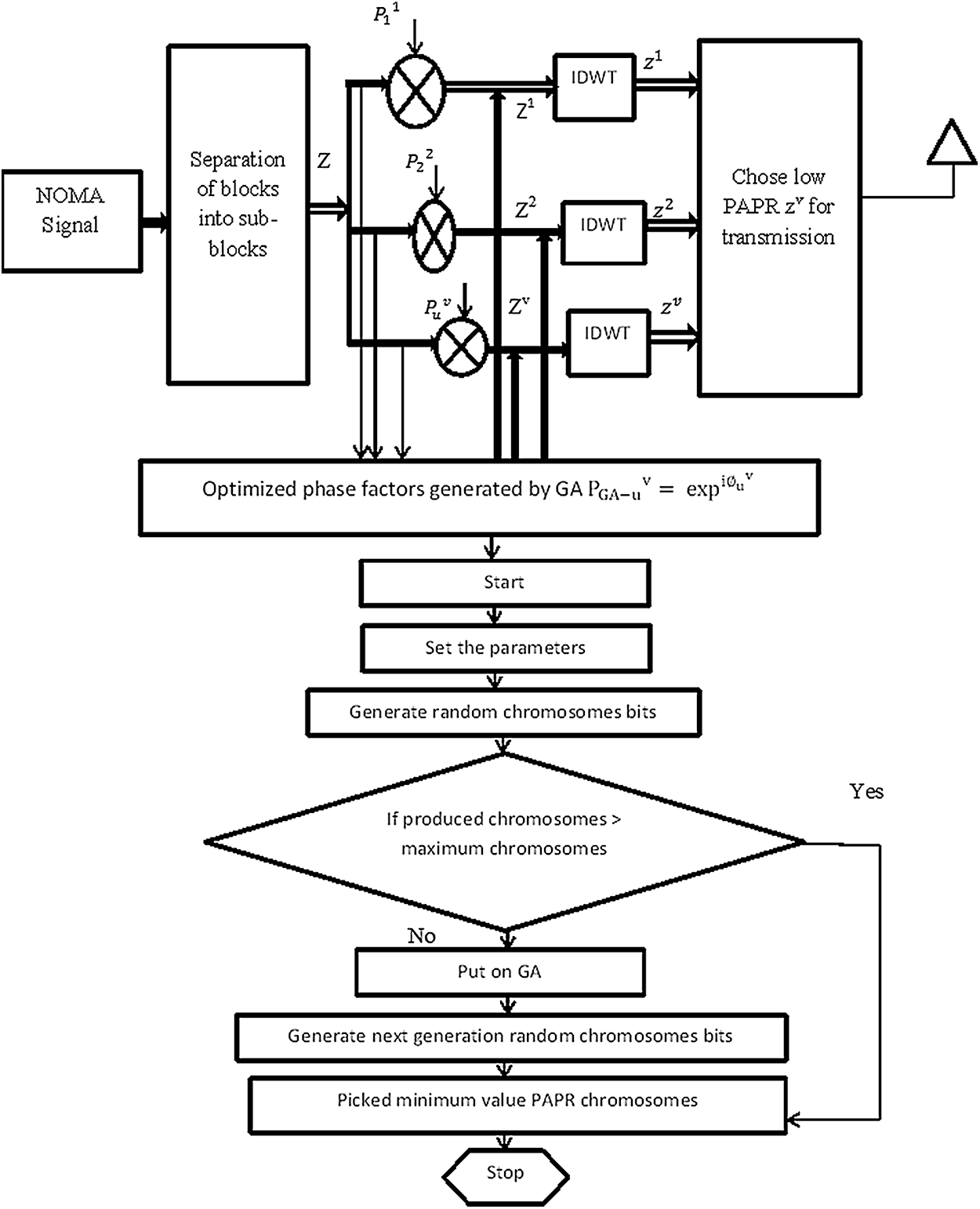
Figure 4: WT-GA-SLM
In this work, we employ MATLAB-2014 to assess the performance of the projected and old-style approaches [23,24]. The parameters of the proposed simulation are indicated in Tab. 1.
Table 1: Simulation parameters
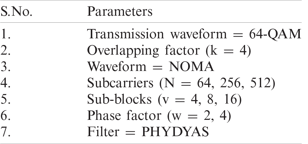
Fig. 5 represents the peak power performance of the NOMA waveform for N number of subcarriers used in the simulation (N = 64, 256, and 512). N = 64, 256, 512 sub-carriers minimize the amplitude power to 8.5, 9.2, and 14 dB respectively, at the CCDF of 10−3. Hence, we can obtain optimal PAPR performance by utilizing N = 64.
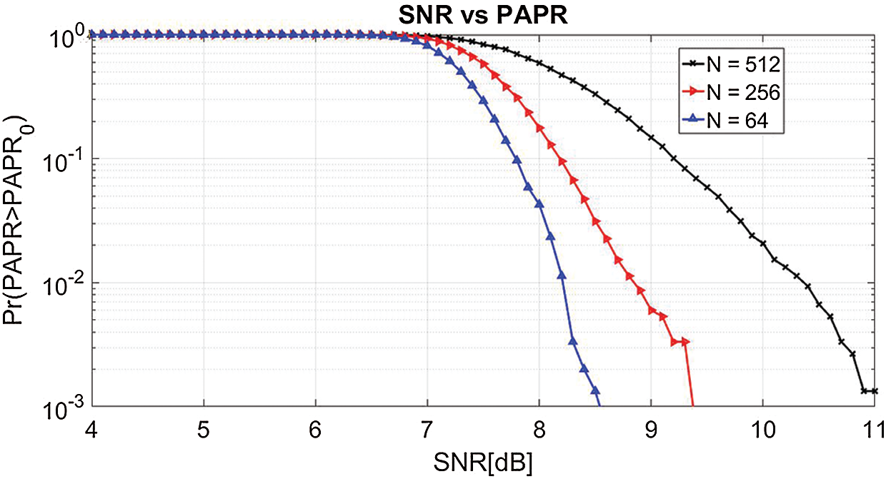
Figure 5: PAPR for different sub-carriers (N)
In Fig. 6, we analyze the peak power reduction capability of the proposed WT-NOMA and FFT-NOMA systems. The simulation results demonstrate that the proposed WT-NOMA significantly reduces the PAPR to 9.8 dB compared with the traditional NOMA (12 dB).
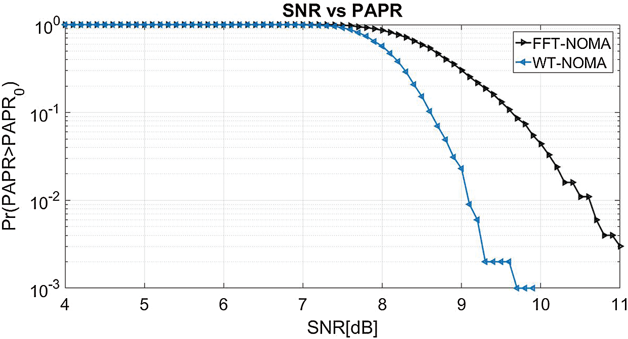
Figure 6: PAPR performance of WT-NOMA vs. FFT-NOMA
The peak power analysis of the proposed WT-SLM and FFT-SLM for the NOMA system is presented in Fig. 7. The original PAPR of NOMA at the CCDF of 10−3 is 11 dB. From the simulation results, the proposed method reduces the peak power to 8.7 dB whereas the conventional SLM shows peak power of 9.8 dB. Accordingly, the proposed method achieves a gain of 1.26 dB compared with to the FFT-SLM.
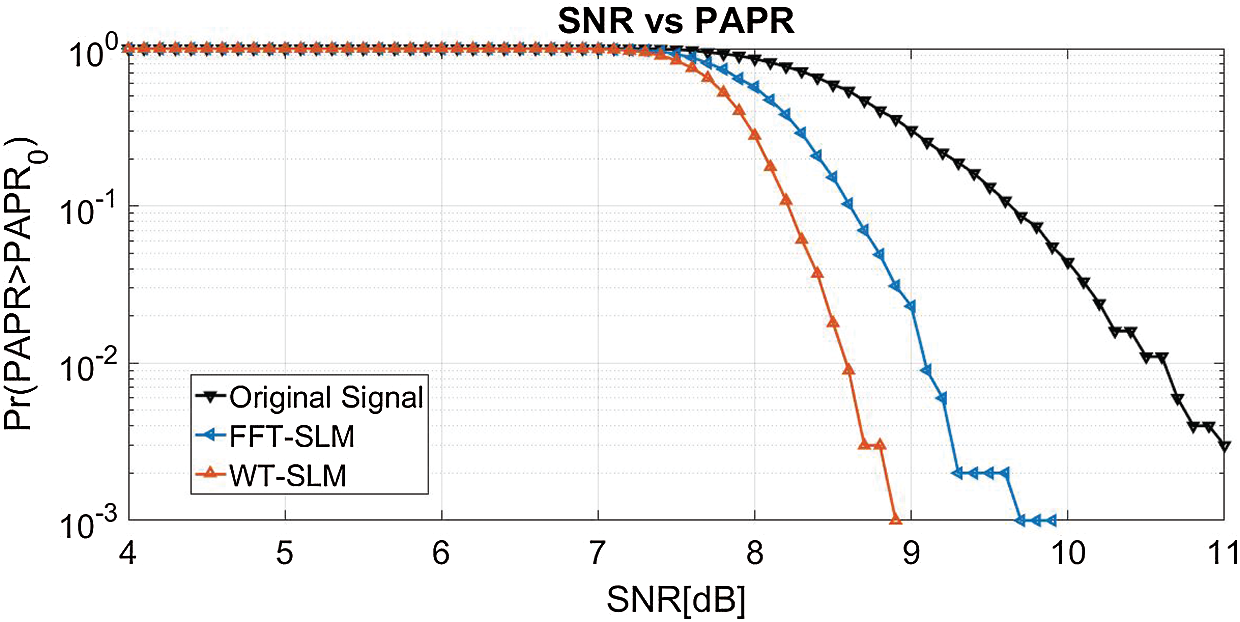
Figure 7: PAPR characteristics
The PAPR analysis of DT-SLM for different sub-blocks (v) is shown in Fig. 8. In the present simulation, v is restricted to 4, 8, and 16 data blocks. The original PAPR of NOMA at the CCDF of 10−3 is 11 dB. The results indicate that the proposed WT-SLM reduces the peak power to 9, 8.2, and 7.4 dB for v = 4, 8, 16 respectively. As projected, the amplitude power of the NOMA signal can be minimized by varying the value of v. From the results, ideal PAPR can be realized using v = 16 in WT-SLM.
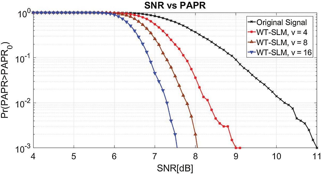
Figure 8: PAPR of WT-SLM with v
In Fig. 9, we investigate the PAPR performance of the proposed WT-PTS and FFT-PTS at CCDF of 10−3. The results show that the proposed method efficiently reduces the amplitude power to 7 dB, whereas the traditional PTS has peak power of 9.4 dB. Hence, WT-SLM has better performance than the traditional PTS.
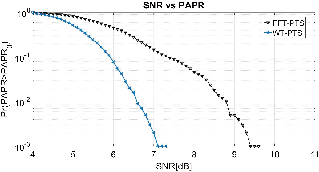
Figure 9: PAPR for WT-PTS and FFT-PTS
The PAPR curve of the recommended WT-PTS for the NOMA wave is indicated in Fig. 10. We confine our simulation outcomes to repetition values v and w equivalent to 2. As estimated, enhanced peak power reduction is realized by changing the values of u and w. At the CCDF of 10-3, WT-PTS minimizes the peak power to 4.2, 5, 6.8, and 8.6 dB for v = 4 w = 4, v = 4 w = 2, v = 2 w = 4, and v = 2 w = 2, respectively, compared with the original PAPR (11 dB). From the curve, optimal PAPR performance can be achieved using v = 4 w = 4 in WT-PTS.
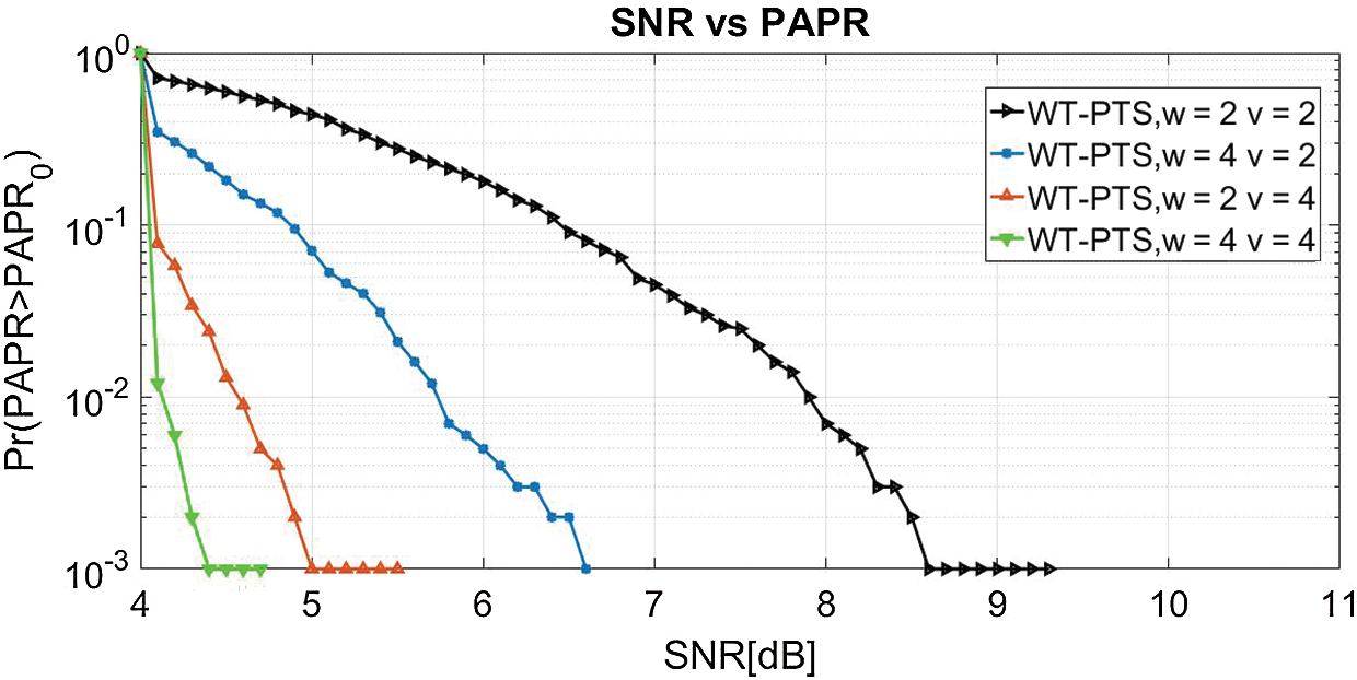
Figure 10: PAPR of WT-PTS with v and w
In the NOMA waveform, the PAPR curve of the proposed SLM-GA is achieved with varying ‘u’, and ‘v’ numbers, as indicated in Fig. 11. The original peak power of the NOMA signal without the reduction method is 11 dB. At the CCDF of 10−3, the peak power is reduced to 4.1 and 5.8 dB for WT-SLM-GA w = 4 and w = 2, respectively. Thus, efficient PAPR performance is obtained using w=4 in WT-SLM-GA.
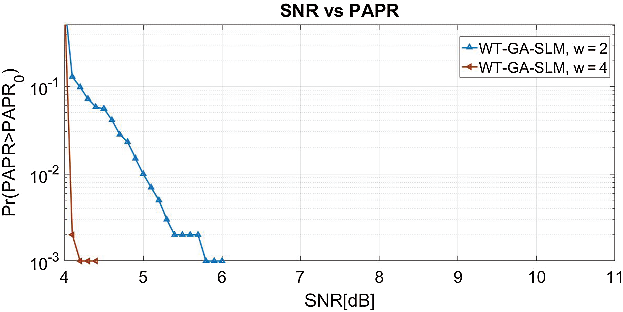
Figure 11: PAPR of WT-GA-SLM with w
In Fig. 12, we compare the performance of the BER curve when the signal is applied to FFT-NOMA and WT-NOMA. From the simulation results, the BER of FFT-NOMA is 10−3 at 7.8 dB SNR. When the signal is passed through WT-NOMA, the BER of 10-3 is obtained at the SNR of 5.3 dB. Hence, WT-NOMA provides better results than FFT-NOMA.
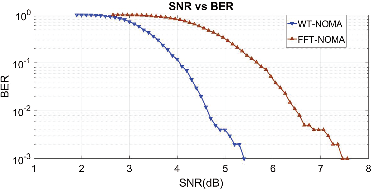
Figure 12: BER of FFT-NOMA and WT-NOMA
To analyze the PAPR performance in NOMA, the SNR verses BER characteristic curves are plotted for the proposed and conventional reduction schemes, in Fig. 13. BER of 10−3 is obtained at SNRs of 4.2 dB for WT-SLM-GA w = 4, 6.8 dB for WT-PTS v = 4, w = 4, 6.2 dB for WT-SLM v = 16, 8.4 dB for FFT-SLM, and 10.2 dB for FFT-PTS. Therefore, WT-SLM-GA outperforms other reduction schemes.
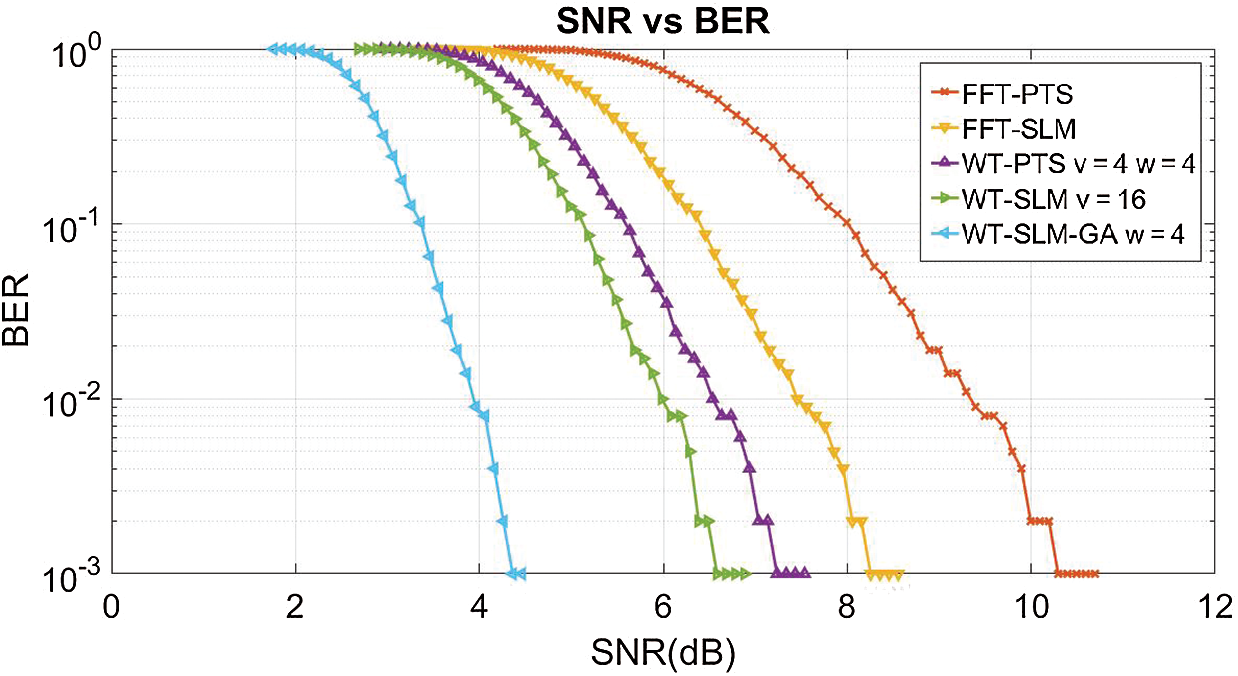
Figure 13: BER curve
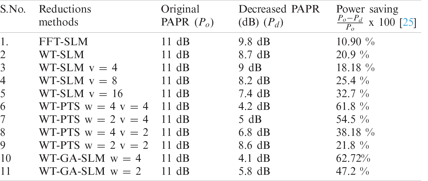
Tabs. 2 and 3 indicate the gain and power saving obtained by the reduction methods, respectively.
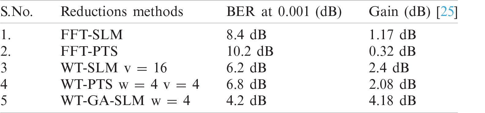
Table 3: Power saving of reduction approaches
We propose a novel peak power reduction method for the NOMA waveform. For the first time, WT blocks are introduced into the NOMA structure. Time-domain NOMA signals are generated and processed by applying inverse WT to acquire a fair amount of sub-blocks with a minimal number of IFFTs. Hence, NOMA-based WT (WT-NOMA) gains better PAPR and BER than the conventional NOMA (FFT-NOMA). The peak power of the transmitted WT-NOMA signals is studied by modifying the PTS and SLM techniques and SLM and PTS techniques increases the complexity of the WT-NOMA system. Therefore, we introduce a GA-based SLM method for the WT-NOMA waveform. Moreover, the proposed WT-centered reduction methods are compared with conventional SLM, PTS, and NOMA (FFT-NOMA). From the simulation analysis, WT-SLM v = 16, WT-PTS v = 4 w = 4, and WT-GA-SLM w = 4, obtain the best performance. The amplitude power is reduced to 7.4, 4.2, and 4.1 dB compared with that of the original PAPR (11 dB). The conventional SLM, PTS and FFT-NOMA systems are outperformed. We also plot the BER curve to investigate the performance of the best proposed methods and traditional methods. The outcomes demonstrate that the BER performance of WT-GA-SLM better than that of SLM v = 16, PTS w = 4 v = 4, FFT-SLM, and FFT-NOMA.
Acknowledgement: The authors would like to thank the editors of CMC and the anonymous reviewers for their time in reviewing this manuscript. The authors also acknowledge JECRC University for providing a lab facility.
Funding Statement: The authors received no specific funding for this study.
Conflicts of Interest: The authors declare that they have no conflicts of interest to report regarding the present study.
1. A. Kumar and M. Gupta, “A novel modulation technique for 5G mobile communication system,” American Journal of Applied Sciences, vol. 12, no. 9, pp. 602–605, 2015. [Google Scholar]
2. X. Zhang, L. Chen, J. Qiu and J. Abdoli, “On the waveform for 5G,” IEEE Communications Magazine, vol. 54, no. 11, pp. 74–80, 2016. [Google Scholar]
3. G. Kongara, C. He, L. Yang and J. Armstrong, “A comparison of CP-OFDM, PCC-OFDM and UFMC for 5G uplink communications,” IEEE Access, vol. 7, pp. 157574–157594, 2019. [Google Scholar]
4. G. Liu, Z. Wang, J. Hu, Z. Ding and P. Fan, “Cooperative NOMA broadcasting/multicasting for low-latency and high-reliability 5G cellular V2X communications,” IEEE Internet of Things Journal, vol. 6, no. 5, pp. 7828–7838, 2019. [Google Scholar]
5. Y. Saito, Y. Kishiyama, A. Benjebbour, T. Nakamura, A. Li et al., “Non-orthogonal multiple access (NOMA) for cellular future radio access,” in 2013 IEEE 77th Vehicular Technology Conf. (VTC SpringDresden, pp. 1–5, 2013. [Google Scholar]
6. K. Tahkoubit, A. Ali-Pacha, H. Shaiek and D. Roviras, “Iterative dichotomy PAPR reduction method for multicarrier waveforms,” IEEE Communications Letters, vol. 23, no. 11, pp. 2073–2076, 2019. [Google Scholar]
7. I. Baig, N. U. Hasan, M. Zghaibeh, I. U. Khan and A. S. Saand, “A DST precoding based uplink NOMA scheme for PAPR reduction in 5G wireless network,” in 7th Int. Conf. on Modeling, Simulation, and Applied Optimization, Sharjah, pp. 1–4, 2017. [Google Scholar]
8. I. Baig, “On the PAPR reduction: A novel filtering based Hadamard transform precoded uplink MC-NOMA scheme for 5G cellular networks,” in 1st Int. Conf. on Computer Applications & Information Security, Riyadh, pp. 1–4, 2018. [Google Scholar]
9. I. Baig, “A precoding-based multicarrier non-orthogonal multiple access scheme for 5G cellular networks,” IEEE Access, vol. 5, pp. 19233–19238, 2017. [Google Scholar]
10. A. Kumar and M. Gupta, “Peak average power reduction in NOMA by using PTSCT technique,” Recent Patents on Computer Science, vol. 13, no. 3, pp. 502–507, 2019. [Google Scholar]
11. M. H. Aghdama and A. A. Sharifib, “PAPR reduction in OFDM systems: An efficient PTS approach based on particle swarm optimization,” ICT Express, vol. 5, no. 3, pp. 178–181, 2019. [Google Scholar]
12. M. Tören and C. Çiflikli, “Peak-to-average-power-ratio reduction methods with wavelet transform in MIMO-OFDM,” IETE Journal of Research, vol. 64, no. 3, pp. 415–421, 2018. [Google Scholar]
13. W. Rong, J. Cai and X. Yu, “Low complexity PTS PAPR reduction scheme for UFMC systems,” Cluster Computing, vol. 20, pp. 3427–3440, 2017. [Google Scholar]
14. H. Rathore and A. Kumar, “Reduction of peak average power ratio for FBMC waveform with P-PTS technique,” International Journal of Sensors, Wireless Communications and Control, vol. 10, no. 1, pp. 47–54, 2020. [Google Scholar]
15. A. S. Fathy, M. S. E. Mahallawy, S. M. Gasser and E. A. A. Hagras, “PAPR reduction based on genetic algorithm for PTS wavelet-OFDM systems,” in Proc. of the 2019 3rd Int. Conf. on Advances in Artificial Intelligence, New York, NY, USA: Association for Computing Machinery, pp. 58–62, 2019. [Google Scholar]
16. A. Lahcena, A. Saidab and A. Adela, “Low computational complexity PTS scheme for PAPR reduction of MIMO-OFDM systems,” Procedia Engineering, vol. 181, pp. 876–883, 2017. [Google Scholar]
17. V. Sudha and D. Sriram Kumar, “Low complexity PAPR reduction in SLM-OFDM system using time domain sequence separation,” Alexandria Engineering Journal, vol. 57, no. 4, pp. 3111–3115, 2018. [Google Scholar]
18. K. Mhatrea and U. P. Khotb, “Efficient selective mapping PAPR reduction technique,” Procedia Computer Science, vol. 45, pp. 620–627, 2015. [Google Scholar]
19. A. Kumar, “A novel hybrid PAPR reduction technique for NOMA and FBMC system and its impact in power amplifiers,” IETE Journal of Research, vol. 5, no. 1, pp. 1–17, 2019. [Google Scholar]
20. R. Ayeswarya and A. N. Prabha, “Fractional wavelet transform based PAPR reduction schemes in multicarrier modulation system,” IETE Journal of Research, 2019. https://doi.org/10.1080/03772063.2019. 1621685. [Google Scholar]
21. R. W. Bauml, R. F. Fischer and J. B. Huber, “Reducing the peak-to-average power ratio of multicarrier modulation by selected mapping,” Electronics Letter, vol. 32, no. 22, pp. 2056–2057, 1996. [Google Scholar]
22. S. H. Muller and J. B. Huber, “OFDM with reduced peak to-average power ratio by optimum combination of partial transmit sequences,” Electronics Letter, vol. 33, no. 5, pp. 368–369, 1997. [Google Scholar]
23. Y. A. A. Jawhar, N. S. M. Shah, M. A. Taher, M. S. Ahmed and K. N. Ramli, “An enhanced partial transmit sequence segmentation schemes to reduce the PAPR in OFDM systems,” International Journal of Advanced Computer Science and Applications, vol. 7, no. 12, pp. 66–75, 2017. [Google Scholar]
24. P. P. Kumar and K. K. Kishore, “BER and PAPR analysis of UFMC for 5G communications,” Indian Journal of Science and Technology, vol. 9, no. 1, pp. 1–6, 2016. [Google Scholar]
25. F. H. Raab, P. Asbeck, S. Cripps, P. B. Kenington and B. Z. Popovic, et al., “Power amplifier and transmitters for RF and microwave,” IEEE Transactions Microwave Theory and Techniques, vol. 50, no. 3, pp. 814–826, 2002. [Google Scholar]
 | This work is licensed under a Creative Commons Attribution 4.0 International License, which permits unrestricted use, distribution, and reproduction in any medium, provided the original work is properly cited. |