DOI:10.32604/cmc.2021.018245
| Computers, Materials & Continua DOI:10.32604/cmc.2021.018245 | |
| Article |
A Novel Beamforming Emulating Photonic Nanojets for Wireless Relay Networks
1College of Engineering and Technology, American University of the Middle East, Kuwait
2Department of Electrical and Electronics Engineering, Middle East Technical University, Ankara, 06800, Turkey
*Corresponding Author: Ibrahim Mahariq. Email: ibrahim.maharik@aum.edu.kw
Received: 01 March 2021; Accepted: 02 April 2021
Abstract: In this article, a low-cost electromagnetic structure emulating photonic nanojets is utilized to improve the efficiency of wireless relay networks. The spectral element method, due to its high accuracy, is used to verify the efficiency of the proposed structure by solving the associate field distribution. The application of optimal single-relay selection method shows that full diversity gain with low complexity can be achieved. In this paper, the proposed technique using smart relays combines the aforementioned two methods to attain the benefits of both methods by achieving the highest coding and diversity gain and enhances the overall network performance in terms of bit error rate (BER). Moreover, we analytically prove the advantage of using the proposed technique. In our simulations, it can be shown that the proposed technique outperforms the best known state-of-the-art single relay selection technique. Furthermore, the BER expressions obtained from the theoretical analysis are perfectly matched to those obtained from the conducted simulations.
Keywords: Wireless relay networks; cooperative diversity techniques; relay selection; network beamforming techniques
In wireless communication systems, several techniques have recently been suggested to improve the overall system performance in terms of bit error rate (BER) or achievable data rate [1–9]. Some of them are based on increasing or optimizing the transmitted power or based on using efficient error detection and correction to improve the overall coding gain of the BER curves. Recent techniques are implemented based on improving diversity gain by applying time diversity, frequency, special diversity or a combination of them. Time diversity can improve the BER curve by sending the same information symbols several times in different time slots. Frequency diversity enhances the BER performance by transmitting the same information symbols several times in different frequency slots.
Spatial diversity techniques also known as multiple-input multiple-output (MIMO) techniques can improve the BER performance by sending the same information symbols several times using different transmitted antennas at the same time and frequency slots. The latter techniques are considered as being the most efficient ones since they do not require additional time or frequency slots [3–9]. To improve both diversity and coding gain, many recent techniques that combine some of the diversity techniques have been proposed such as space-frequency coding (SFC) techniques and space-time coding (STC) techniques [2,8].
Other special diversity techniques based on beamforming schemes [4–6] which multiplies the transmitted antennas by certain factors to enable beam steering in the direction of the receiving antennas have been suggested to improve the overall performance in terms of BER and the achievable data rate. This is because MIMO communication systems are greatly affected by the multiuser interference and channel impairments such as the time varying fading caused by multi path propagation [1–9].
In many applications, it is difficult, due to several limitations, to have many antennas on the mobile station. To solve this problem, a cooperative communication system can be performed instead of applying the conventional MIMO systems by using relay nodes distributed randomly between the transmitted antennas. These relays are used either to just amplify-and-forward (AF) the received signals or they can decode the information signals before broadcasting them to the received antenna. Therefore, in cooperative communication networks, relay-nodes will jointly process the received data messages before broadcasting them using their antennas toward the receiving entities, which will combine all the received copies from different paths to improve the spatial diversity gain. Such techniques are called the multi-antenna diversity techniques that incorporate the use of one-way or two-way relaying schemes [1–7].
Recently, many efficient relaying techniques are proposed to achieve the full diversity gain and the highest coding gain such as distributed space time coding techniques which allow the relays to apply space time coding technique to improve the overall system performance [2–3], distributed beamforming techniques which allow the relay to form a beam in the direction of the receiver to improve the overall received signal-to-noise-ration (SNR) thus offering higher coding gain [4–6].
The previous two techniques use all relay nodes between the communicating terminals. To improve the previous techniques and achieve the full diversity gain with low decoding complexity in non-orthogonal relay-node networks and without using all relay nodes between the communicating terminals, relay selection techniques have been proposed [10–19]. In the latter techniques, a single relay [10–12] or two relays [13–14] among several relay nodes between the communicating terminals are selected to amplify and forward the received signal to decode and forward it to the destination. These techniques enjoy full diversity gain and low overall complexity by using only one or two relays. In [10–12] a single relay-node is selected among a set of relay nodes to maximize either the SNR or the achievable data rate. In [11–12], a criterion is proposed to select the optimal relay node using the max-min scheme.
In the conventional wireless relay networks, each relay node is equipped with a single antenna or several antennas to receive the signal before amplifying and forwarding it. In this paper, the received signal is improved prior to processing it by focusing the beam to the relay antenna using a specific element designed and simulated by the spectral element method (SEM) which is recently applied in electromagnetic radiation to improve the channel gain of each relay node.
In order to achieve accurate results, SEM has been utilized in this study for the computation of transmitted and scattered fields. In fact, this method has been recently applied in electromagnetic radiation and/or scattering problems due to its accuracy and the relatively lower computational requirements [20–26]. For accuracy demonstration, the authors in [24] compared the computational relative error among SEM, finite element method and finite difference method in several one- and two-dimensional problems and reported exceptional accuracy for the case of SEM with much less computational cost.
In this work, both beamforming technique emulating photonic nanojet behavior [26–30] and the optimal single-relay selection method have been combined in this proposed technique to obtain the benefits of both methods. An electromagnetic structure is proposed to enhance the efficiency of the relay nodes while the relay selection method is improved to achieve the full diversity gain with low decoding complexity. By combining both methods, the proposed technique using smart relay enjoys the highest coding and diversity gain and improves the overall system performance in terms of BER. In this article, we prove that the performance of the suggested strategy is better than the performance of the best known state-of-the-art single relay selection technique. Furthermore, we prove that the BER mathematical expression of our theoretical analysis is perfectly match those obtained from the conducted simulations.
For our system model, we consider a one-way relay network consisting of a single-antenna transmitter
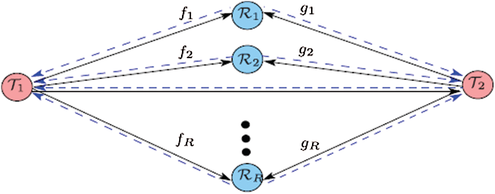
Figure 1: System model
3 The Proposed Relay Selection Technique
In this proposed technique, one intermediate relay node will be chosen from the R relay nodes where the optimal single relay node
After selecting the optimal relay node among all
where
where
Note here that the decoding complexity is very low, as a symbol-wise decoder which enjoys a linear decoding complexity is utilized to detect the received data messages. In DF protocol, the selected relay
The selected relay node
where
Note here that the decoding complexity is very low, as a symbol-wise decoder which enjoys a linear decoding complexity is being used to detect the received data messages.
4 Definition of the Computational Problem
The computational domain consists of a lossy dielectric hemi-cylinder (whose radius is Ri and complex permittivity is
in which;
The field governed by the above equation decays rapidly as it propagates from the source location. That is; the assumption of such a radiating source is put in order to imitate the real situation of transmitting antenna in GHz ranges. The following frequency-domain Helmholtz equation must be satisfied inside the computational domain (except the PML):
where
Measurements of complex permittivity for several types of materials at wide range of frequencies have been performed in many studies [32–36]. For instance, determination of permittivity for glass with planner and convex surfaces over a range of 75 MHz to 6 GHz is presented in [32], while the permittivity determination of polytetrafluorethylene, polyvinylchloride (PVC), and acrylic glass is performed at much higher frequencies and presented in Reference [33]. In this work, the permittivity of polyoxymethylene is considered at 25 GHz. For this material, the real part of permittivity is
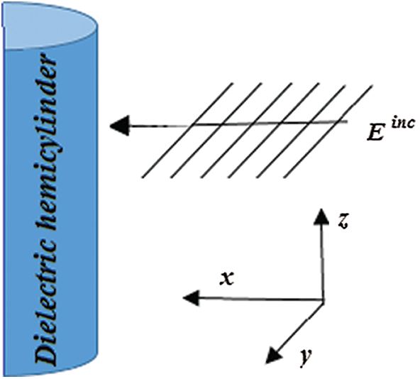
Figure 2: Schematic representation of the electromagnetic structure which includes a lossy dielectric hemi-cylinder excited by a z-polarized wave
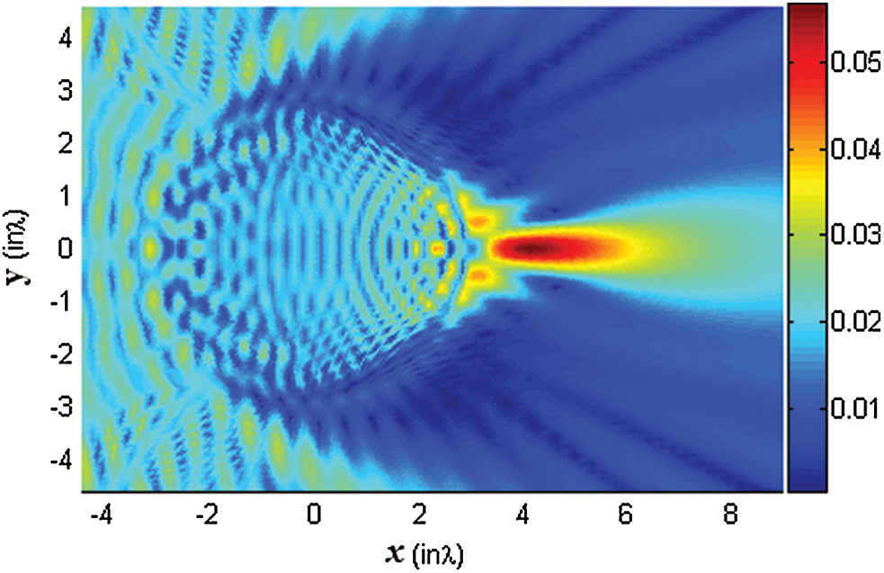
Figure 3: A typical photonic nanojet at optical frequencies generated from a lossless dielectric micro-cylinder (Source [30])
In Fig. 4, the solution of the electromagnetic structure as obtained by SEM is presented; (a) the colormapping of the total field magnitude is shown, (b) the 3D view of part (a), (c) the colormapping of the intensity, and in part (d) the corresponding field magnitude at y = 0 is plotted. The incident field is adjusted so that it takes a unit magnitude when it reaches the cylinder. In other words, the field plotted in Fig. 3 is normalized with the incident one in order to realize the effect of the hemi-cylinder.
As it can be clearly seen from the Fig. 4, the wave is focused and a beam of magnitude |
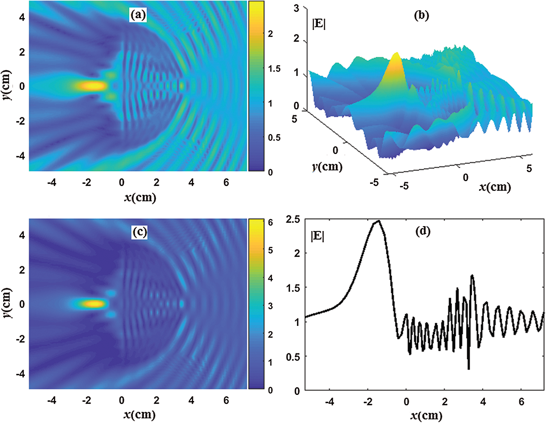
Figure 4: The solution of the electromagnetic structure as obtained by SEM; (a) the colormapping of the total field magnitude, (b) the 3D view of part (a), (c) the colormapping of the field intensity, (d) the corresponding field magnitude at y = 0
As explained in the manuscript, we propose the addition of a hemi-cylindrical object (with a realistic complex permittivity values) that focuses the incident wave and hence amplifies the signal before it is just received by the wireless relay at communication frequency ranges. This focusing technique is emulated from photonic nanojets at optical frequencies. In order to verify the design, electromagnetic simulation is required to show that the field magnitudes are increased due to this proposed structure. The field magnitude is then used to prove that BER is decreased.
For this structure to be well utilized, the antenna of the receiver must be placed in the region where the wave focusing takes place. Fortunately, the focal point has almost stationary position and is dependent on material permittivity. Another important fact is that, if the transmitting source change its location over a range of around 30 degrees, the corresponding the focal point stays within the axis where the receiving antenna exists. The last two points in addition to others reported for photonic jets [37,38] are considered by the authors as a future work. In addition, other properties of photonic jets [39–41] may be emulated for the purpose of utilizing them in wireless relay networks.
In this section, the mathematical BER expression of the proposed smart relay selection strategy is discussed. Let us first consider the assumptions discussed in Section 2 and assume that the information symbols are drawn from binary phase shift keying (BPSK) constellation. Similar to [10–14], we consider the case of ideal relays in which the selected relay
In our suggested strategy, the proposed relay selection technique based on the max-min criteria explained in (1) is applied to select the best relay node
where
In this section, we introduce the simulation results as well as the analytical results proposed in Section 5. Fig. 5 shows the BER vs. the SNR of a wireless relay network composed of a transmitter T1, a receiver T2, with no direct link between them, and two relay nodes (
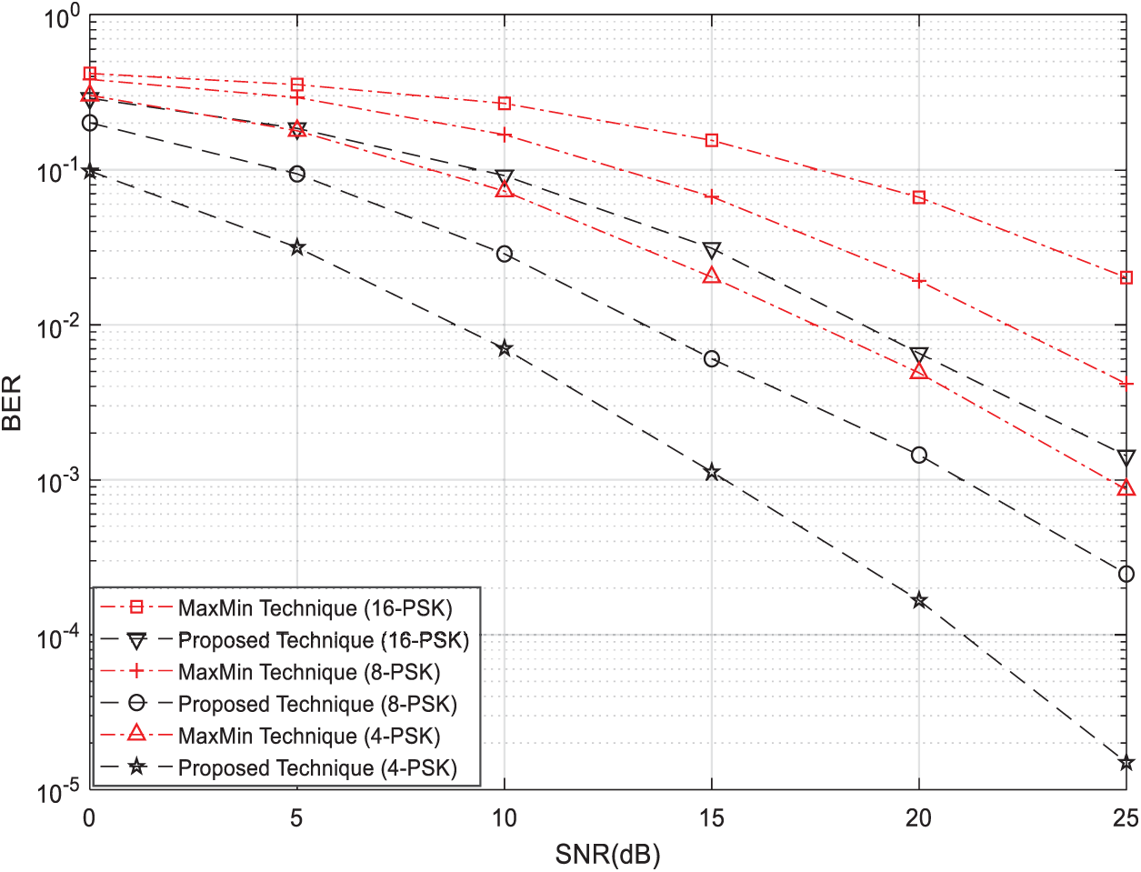
Figure 5: BER vs. SNR for single relay selection strategies using the AF protocol with 4-PSK, 8-PSK, and 16-PSK modulations and
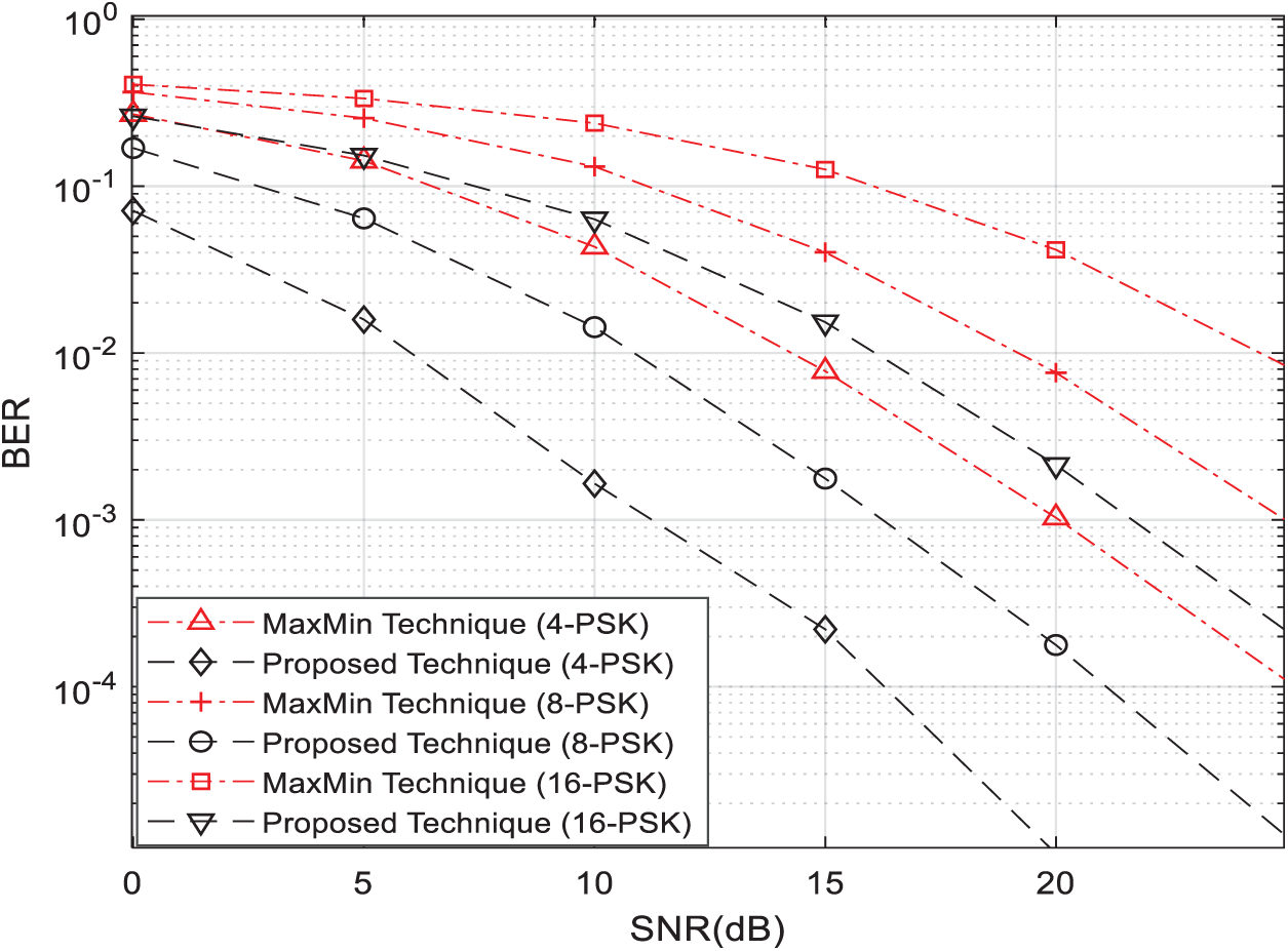
Figure 6: BER vs. SNR for single relay selection strategies using the AF protocol with 4-PSK, 8-PSK, and 16-PSK modulations and
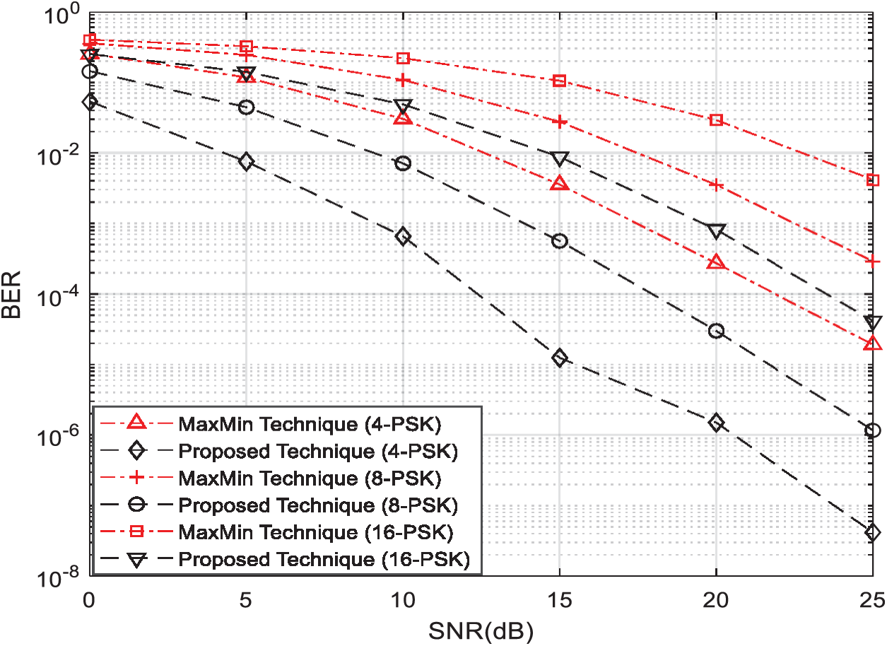
Figure 7: BER vs. SNR for single relay selection strategies using the AF protocol with 4-PSK, 8-PSK, and 16-PSK modulations and
Fig. 5 shows the BER vs. the SNR of a wireless relay network composed of a transmitter T1, a receiver T2, with no direct link between them, and three relay nodes (
From Figs. 5–7, we can clearly observe that our proposed single-relay-node selection technique outperforms the best-known single-relay selection technique [11,12] under all scenarios. Moreover, Fig. 8 clearly shows that our simulation results match with our theoretical results given by (9) in Section 5.
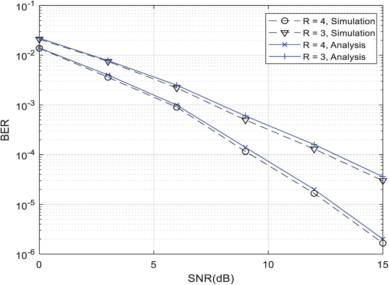
Figure 8: Theoretical and simulated BER performance vs. SNR for the suggested strategy with R = 3 and R = 4
In this article, generation of photonic nanojet at optical frequencies resulted from illumination of lossless dielectric micro-cylinders is emulated for wireless networks frequencies. That is; we merged both, beamforming approach, and the optimal single-relay selection approach that is applied in wireless relay network, in the proposed strategy to get the benefits of both approaches. The beamforming approach calculated by SEM is modified to calculate the efficiency of the relay nodes while the relay selection method is improved to achieve the full diversity gain. Therefore, in this paper, an enhanced single relay selection strategy is introduced to be used for wireless relay networks using smart relays that offer higher coding gain and enjoy full diversity gain to improve the overall network performance in terms of BER. Furthermore, we proved the advantage of the proposed strategy analytically and through simulations. In our simulations, we show that our proposed strategy outperforms the best known state-of-the-art single relay selection technique. Furthermore, we proved that the BER results obtained from our conducted simulations are perfectly match those obtained from the theoretical analysis.
Funding Statement: This work was supported by College of Engineering and Technology, the American University of the Middle East, Kuwait. Homepage: https://www.aum.edu.kw.
Conflicts of Interest: The authors declare that they have no conflicts of interest to report regarding the present study.
1. S. Alabed, J. Paredes and A. B. Gershman, “A simple distributed space-time coded strategy for two-way relay channels,” IEEE Transactions on Wireless Communications, vol. 11, no. 4, pp. 1260–1265, 2012. [Google Scholar]
2. S. Alabed, M. Pesavento and A. Klein, “Non-coherent distributed space-time coding techniques for two-way wireless relay networks,” EURASIP Special Issue on Sensor Array Processing, vol. 93, no. 12, pp. 3371–3381, 2013. [Google Scholar]
3. S. Alabed and M. Pesavento, “A simple distributed differential transmit beamforming technique for two-way wireless relay networks,” in 16th Int. IEEE/ITG Workshop on Smart Antennas, Dresden, Germany, pp. 243–247, 2012. [Google Scholar]
4. A. Schad, S. Alabed, H. Degenhardt and M. Pesavento, “Bi-directional differential beamforming for multi-antenna relaying,” in 40th IEEE Int. Conf. on Acoustics, Speech and Signal Processing, Brisbane, pp. 2884–2888, 2015. [Google Scholar]
5. S. Alabed, “Performance analysis of differential beamforming in decentralized networks,” International Journal of Electrical and Computer Engineering, vol. 8, no. 3, pp. 1692–1700, 2018. [Google Scholar]
6. S. Alabed, “Computationally efficient multi-antenna techniques for multi-user two-way wireless relay networks,” International Journal of Electrical and Computer Engineering, vol. 8, no. 3, pp. 1684–1691, 2018. [Google Scholar]
7. S. Alabed, J. Paredes and A. Gershman, “A low complexity decoder for quasi-orthogonal space-time block codes,” IEEE Transactions on Wireless Communications, vol. 3, no. 10, pp. 988–994, 2011. [Google Scholar]
8. S. Alabed, M. Pesavento and A. Klein, “Relay selection-based space-time coding for two-way wireless relay networks using digital network coding,” in Proc. of the 10th Int. Symp. on Wireless Communication Systems, Ilmenau, Germany, pp. 1–5, 2013. [Google Scholar]
9. Y. Li, R. Louie and B. Vucetic, “Relay selection with network coding in two-way relay channels,” IEEE Transactions on Vehicular Technology, vol. 59, no. 9, pp. 4489–4499, 2010. [Google Scholar]
10. G. Chen, Z. Tian, Y. Gong, Z. Chen and J. Chambers, “Max-ratio relay selection in secure buffer-aided cooperative wireless networks,” IEEE Transactions on Information Forensics and Security, vol. 9, no. 4, pp. 719–729, 2014. [Google Scholar]
11. S. Atapattu, Y. Jing, H. Jiang and C. Tellambura, “Relay selection schemes and performance analysis approximations for two-way networks,” IEEE Transactions Communications, vol. 61, no. 3, pp. 987–998, 2012. [Google Scholar]
12. S. Alabed, “Performance analysis of two-way DF relay selection techniques,” Special Issue on ICT Convergence in the Internet of Things, vol. 2, no. 3, pp. 91–95, 2016. [Google Scholar]
13. S. Alabed, “Performance analysis of bi-directional relay selection strategy for wireless cooperative communications,” EURASIP Journal on Wireless Communications and Networking, vol. 2019, no. 97, pp. 1–11, 2019. [Google Scholar]
14. G. Cai, Y. Fang, G. Han, J. Xu and G. Chen, “Design and analysis of relay-selection strategies for two-way relay network-coded DCSK systems,” IEEE Transactions on Vehicular Technology, vol. 67, no. 2, pp. 1–13, 2017. [Google Scholar]
15. T. Nguyen, T. Minh, P. Tran, M. Voznak, T. Duy et al., “Performance enhancement for energy harvesting based two-way relay protocols in wireless ad-hoc networks with partial and full relay selection methods,” Ad Hoc Networks, vol. 84, no. 4, pp. 178–187, 2019. [Google Scholar]
16. S. Zhou, J. Xu and Z. Niu, “Interference-aware relay selection technique for two-hop relay networks with multiple source-destination pairs,” IEEE Transactions on Vehicular Technology, vol. 62, no. 5, pp. 2327–2338, 2013. [Google Scholar]
17. M. Ju, K. Hwang and H. Song, “Relay selection of cooperative diversity networks with interference-limited destination,” IEEE Transactions on Vehicular Technology, vol. 62, no. 9, pp. 4658–4665, 2013. [Google Scholar]
18. G. Cai, Y. Fang and G. Han, “Design of an adaptive multiresolution M-ary DCSK system,” IEEE Communications Letters, vol. 21, no. 1, pp. 60–63, 2017. [Google Scholar]
19. M. Simon and M. Alouini, Digital Communication Over Fading Channels: A Unified Approach to Performance Analysis, 1{\rm st} ed., Hoboken, NJ, USA: Wiley-Interscience, 2000. [Google Scholar]
20. O. Z. Mehdizadeh and M. Paraschivoiu, “Investigation of a two-dimensional spectral element method for Helmholtz’s equation,” Journal of Computational Physics, vol. 189, no. 1, pp. 111–129, 2003. [Google Scholar]
21. J. Lee, T. Xiao and Q. H. Liu, “A 3-D spectral-element method using mixed-order curl conforming vector basis functions for electromagnetic fields,” IEEE Transactions on Microwave Theory and Techniques, vol. 54, no. 12, pp. 4141–4148, 2006. [Google Scholar]
22. I. Mahariq, M. Kuzuoğlu and H. I. Tarman, “On the attenuation of perfectly matched layer in electromagnetic scattering problems with spectral element method,” Applied Computational Electromagnetics Society Journal, vol. 29, pp. 701–710, 2014. [Google Scholar]
23. I. Mahariq and A. Erciyas, “A spectral element method for the solution of magnetostatic fields,” Turkish Journal of Electrical Engineering & Computer Sciences, vol. 25, pp. 2922–2932, 2017. [Google Scholar]
24. I. Mahariq, H. Kurt and M. Kuzuoğlu, “Questioning degree of accuracy offered by the spectral element method in computational electromagnetics,” Applied Computational Electromagnetics Society Journal, vol. 30, pp. 698–705, 2015. [Google Scholar]
25. I. Mahariq, “On the application of the spectral element method in electromagnetic problems involving domain decomposition,” Turkish Journal of Electrical Engineering & Computer Sciences, vol. 25, pp. 1059–1069, 2017. [Google Scholar]
26. I. Mahariq, H. Kurt, H. I. Tarman and M. Kuzuoglu, “Photonic nanojet analysis by spectral element method,” IEEE Photonics Journal, vol. 6, no. 5, pp. 1–14, 2014. [Google Scholar]
27. Z. Chen, A. Taflove and V. Backman, “Photonic nanojet enhancement of backscattering of light by nanoparticles: A potential novel visible-light ultramicroscopy technique,” Optics, vol. 12, no. 7, pp. 1214–1220, 2004. [Google Scholar]
28. A. Heifetz, K. Huang, A. V. Sahakian, X. Li, A. Taflove et al., “Experimental confirmation of backscattering enhancement induced by a photonic jet,” Applied Physics Letters, vol. 89, no. 22, pp. 1–4, 2006. [Google Scholar]
29. I. Mahariq, I. H. Giden, H. Kurt, O. V. Minin and I. V. Minin, “Strong electromagnetic field localization near the surface of hemicylindrical particles,” Optical and Quantum Electronics, vol. 50, pp. 1–8, 2017. [Google Scholar]
30. I. Mahariq, T. Abdeljawad, A. Karar, S. Alboon, H. Kurt et al., “Photonic nanojets and whispering gallery modes in smooth and corrugated micro-cylinders under point-source illumination,” Photonics, vol. 7, no. 50, pp. 1–11, 2020. [Google Scholar]
31. I. Mahariq and H. Kurt, “Strong field enhancement of resonance modes in dielectric microcylinders,” Journal of the Optical Society of America B, vol. 33, no. 4, pp. 656–662, 2016. [Google Scholar]
32. A. Cenanovic, S. Martius, A. Kilian, J. Schur and L. Schmidt, “Nondestructive complex permittivity determination of glass material with planar and convex surface,” in German Microwave Conf., Darmstadt, Germany, pp. 1–4, 2011. [Google Scholar]
33. T. Zwick, A. Chandrasekhar, C. W. Baks, U. R. Pfeiffer, S. Brebels et al., “Determination of the complex permittivity of packaging materials at millimeter-wave frequencies,” IEEE Transactions on Microwave Theory and Techniques, vol. 54, no. 3, pp. 1001–1010, 2006. [Google Scholar]
34. M. N. Afsar, “Precision millimeter-wave measurements of complex refractive index, complex dielectric permittivity, and loss tangent of common polymers,” IEEE Transactions on Instrumentation and Measurement, vol. 36, no. 2, pp. 530–536, 1987. [Google Scholar]
35. A. Elhawil, L. Zhang, J. Stiens and R. Vounckx, “A quasi-optical free-space method for dielectric constant characterization of polymer materials in mm-wave band,” in Symp. Proc. of IEEE/LEOS Benelux Chapter, Brussels, pp. 187–190, 2007. [Google Scholar]
36. J. Barowski, M. Zimmermanns and I. Rolfes, “Millimeter-wave characterization of dielectric materials using calibrated FMCW transceivers,” IEEE Transactions on Microwave Theory and Techniques, vol. 66, no. 8, pp. 3683–3689, 2018. [Google Scholar]
37. I. V. Minin, O. V. Minin, J. A. Delgado-Notario, J. Calvo-Gallego, J. E. Velázquez-Pérez et al., “Improvement of a terahertz detector performance using the terajet effect in a mesoscale dielectric cube: Proof of concept,” Physica Status Solidi, vol. 14, no. 5, pp. 530–536, 2020. [Google Scholar]
38. Y. Samura, K. Horio, V. Antipov, S. Shipilov, A. Eremeev et al., “Characterization of mesoscopic dielectric cuboid antenna at millimeter-wave band,” IEEE Antennas and Wireless Propagation Letters, vol.~18, no. 9, pp. 1828–1832, 2019. [Google Scholar]
39. Y. X. Ren, X. Zeng, L. M. Zhou, C. Kong, H. Mao et al., “Photonic nanojet mediated back action of dielectric microparticles,” ACS Photonics, vol. 7, no. 6, pp. 1483–1490, 2020. [Google Scholar]
40. Z. Wang, W. Guo, L. Li, B. Lukyanchuk, A. Khan et al., “Optical virtual imaging at 50 nm lateral resolution with a white-light nanoscope,” Nature Communications, vol. 2, no. 218, pp. 1–6, 2011. [Google Scholar]
41. Y. Shen, L. V. Wang and J. T. Shen, “Ultralong photonic nanojet formed by a two-layer dielectric microsphere,” Optics Letters, vol. 39, no. 14, pp. 4120–4123, 2014. [Google Scholar]
 | This work is licensed under a Creative Commons Attribution 4.0 International License, which permits unrestricted use, distribution, and reproduction in any medium, provided the original work is properly cited. |