DOI:10.32604/cmc.2021.018481
| Computers, Materials & Continua DOI:10.32604/cmc.2021.018481 | |
| Article |
Adaptive Relay Selection Scheme for Minimization of the Transmission Time
1Department of Information and Communication Engineering, and Convergence for Intelligent Drone, Sejong University, Seoul, 05006, Korea
2Department of Computer Engineering, and Convergence for Intelligent Drone, Sejong University, Seoul, 05006, Korea
*Corresponding Author: Hyoung-Kyu Song. Email: songhk@sejong.ac.kr
Received: 09 March 2021; Accepted: 10 April 2021
Abstract: As the installation of small cells increases, the use of relay also increases. The relay operates as a base station as well as just an amplifier. As the roles and types of relays become more diverse, appropriate relay selection technology is an effective way to improve communication performance. Many researches for relay selection have been studied to secure the reliability of relay communication. In this paper, the relay selection scheme is proposed for a cooperative system using decode-and-forward (DF) relaying scheme in the mobile communication system. To maintain the transmission rate, the proposed scheme classifies a candidate group considering the outage probability of multiple relays. For the applicable candidate group, the proposed scheme selects the relay considering the amount of data allocated to each user. Therefore, the proposed scheme defines the unit transmission time through each user’s data and relay capacity. Finally, the proposed scheme selects a relay that minimizes the total transmission time through the relay transmission time that calculates the unit transmission time for all users. With this adaptive relay selection scheme, an optimal relay can be assigned for each user. For the same transmission rate and the amount of data, the proposed scheme improves the performance of transmission time and reliability. Simulation results show that the proposed scheme reduces the total transmission time for the same amount of data and signal to noise ratio (SNR).
Keywords: Relay selection; cooperative relay; MIMO; outage probability; transmission time
In upcoming years, the usage of mobile traffic is expected to be massive, and throughput of communication is getting higher. As the usage of mobile data is increased, mobile network is needed to provide higher performance in terms of throughput, latency and reliability.
Current mobile network systems such as long-term evolution (LTE) and 5G new radio (NR) are deployed in a variety of ways to meet the actual needs and possibilities. Meanwhile, there are many cases where sufficient reliability and throughput are not guaranteed in the wireless communication system. For example, in the mmWave bands, although a shorter transmission time interval can be used because of low frequency selectivity, the cell coverage would be limited because of higher path loss, which would inevitably lead to the use of small cell sizes [1]. Also, cells are overloaded due to increased space density and mobile devices [2]. Therefore, the design of a new cell is required.
The future communication network may be a heterogeneous layer network consisting of macrocells, traditional micro/picocells, new local small cells, and relay and other low-power nodes [3]. Specifically, the relay system can be used in various ways in the future wireless mobile communication network. The relay system is one of the techniques to provide sufficient coverage and reliability in the wireless communication system. The relay is used to overcome poor wireless link conditions in a cooperative communication system. By implementing a relay node, the relay node handles and routes data traffic between source and destination. Therefore, the SNR and capacity can be increased. Also, relays can improve the topology, network robustness and power consumption of mobile communication systems. As the wireless backhaul secures sufficient capacity, the mobile station can be a solution for the mobile communication systems that can configure a mobile cell architecture [4–6]. The relay supports mobile group access and can provide new services by supporting access nodes in the Internet of things (IoT) network [3,7].
There are many researches related to relay technologies [8–10]. A relay node can assist a pair of users with one-way (OW) or two-way (TW) traffic patterns [11]. For the same data rate, two-way relaying protocol improves transmission power consumption and spectral than one-way relaying protocol [12]. For this reason, two-way relaying protocols have been studied actively to improve performance [13].
To enhance the capacity and reliability, the multiple-input multiple-output (MIMO) relay system can be considered. MIMO techniques provide higher capacity gain using diversity and multiplexing in a relay system.
This paper proposes the adaptive relay selection scheme to enhance the transmission time of the wireless system. The proposed scheme not only considers the link capacity but also the buffered data traffic of active users. Specifically, the proposed scheme classifies the available relay group and then considers the amount of data assigned to each user. Therefore, the proposed scheme reduces the transmission time while the transmission rate is maintained.
This paper is organized as follows. Section 2 introduces the system model. Section 3 explains the conventional schemes. Section 4 describes the algorithm and advantage of the proposed scheme. Simulation results are shown in Section 5. Finally, Section 6 gives the brief conclusions.
Fig. 1 shows the heterogeneous dense network consisting of multi-small cells. Fig. 2 is one of the small cells in Fig. 1. Also, Fig. 2 shows two-hop MIMO relay wireless system model in a wireless network. The system consists of one source node (
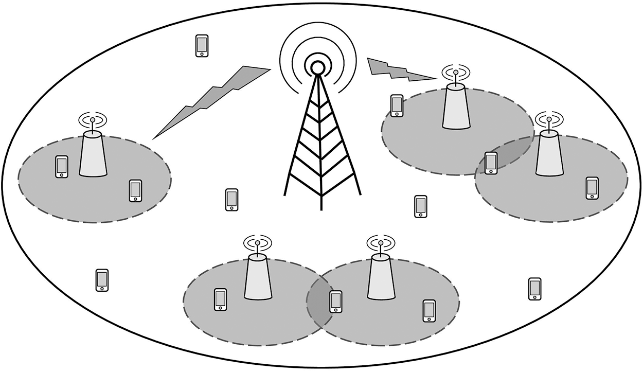
Figure 1: The heterogeneous network for multi-small cells

Figure 2: Two-hop MIMO relaying system

Figure 3: Assigned buffers for each user
System model uses two time slots for signal transmission.
where
Furthermore,
During the second time slots,
where transmitted signal from a set of
3 The Conventional Relay Selection Schemes
This section describes two conventional relay selection schemes. Many researchers have studied for the methods to select relays in different communication environments [14–16]. In each research, there are various schemes for selecting relays, but eventually the relay with the best channel conditions is selected. In other words, the channel condition of
3.1 The Frobenius Norm-Based Selection Scheme
Norm usually uses the Frobenius norm, which is
where
And the diagonal entry in
where
3.2 The MIMO Capacity-Based Selection Scheme
Among the relay selection schemes, the scheme using MIMO relay channel capacity is frequently used [17–19]. The MIMO channel capacity of the
where
As a
4 The Proposed Selection Scheme
The relay selection scheme to reduce the total transmission time is proposed. The selection process consists of two selection steps. In the first step, the transmitter organizes a relay group by selecting qualified relays. According to the result of the first step, in the second step, relays for transmission are selected to minimize the total transmission time. The selection process is described in the following subsection.
4.1 Classification of Relay Candidate Group
For reliability of relaying, qualified
where
The selection process is summarized as follows:
(1) Inputs:
(2) initialize:
(3) for
(4) if
(5)
(6)
(7)
(8) end if
(9) end for
(10) if
(11) break
(12)
(13) else
(14) Go to the second process
(15) end if
The line of (10) explains processing for low SNR environment. The low SNR environment can make every
However, to prevent waste of bandwidth, in proposed algorithm,
4.2 Relay Selection to Minimize the Transmission Time
In this section, the process to allocate relays to users is performed for minimization of the total transmission time. In this process, two cases are considered. The cases are determined according to
where
In the other case,
where
In other words,
The detailed description is summarized as follows:
(1) Inputs:
(2) Initialize:
(3) for
(4)
(5) for
(6) If
(7)
(8) end for
(9) end for
The proposed scheme classifies a candidate relay group with non-outage. For a configured group of candidate relays, the relay with the minimum transmission time is selected. The proposed scheme can select a relay that reduces the transmission time while the BER performance through two steps is improved.
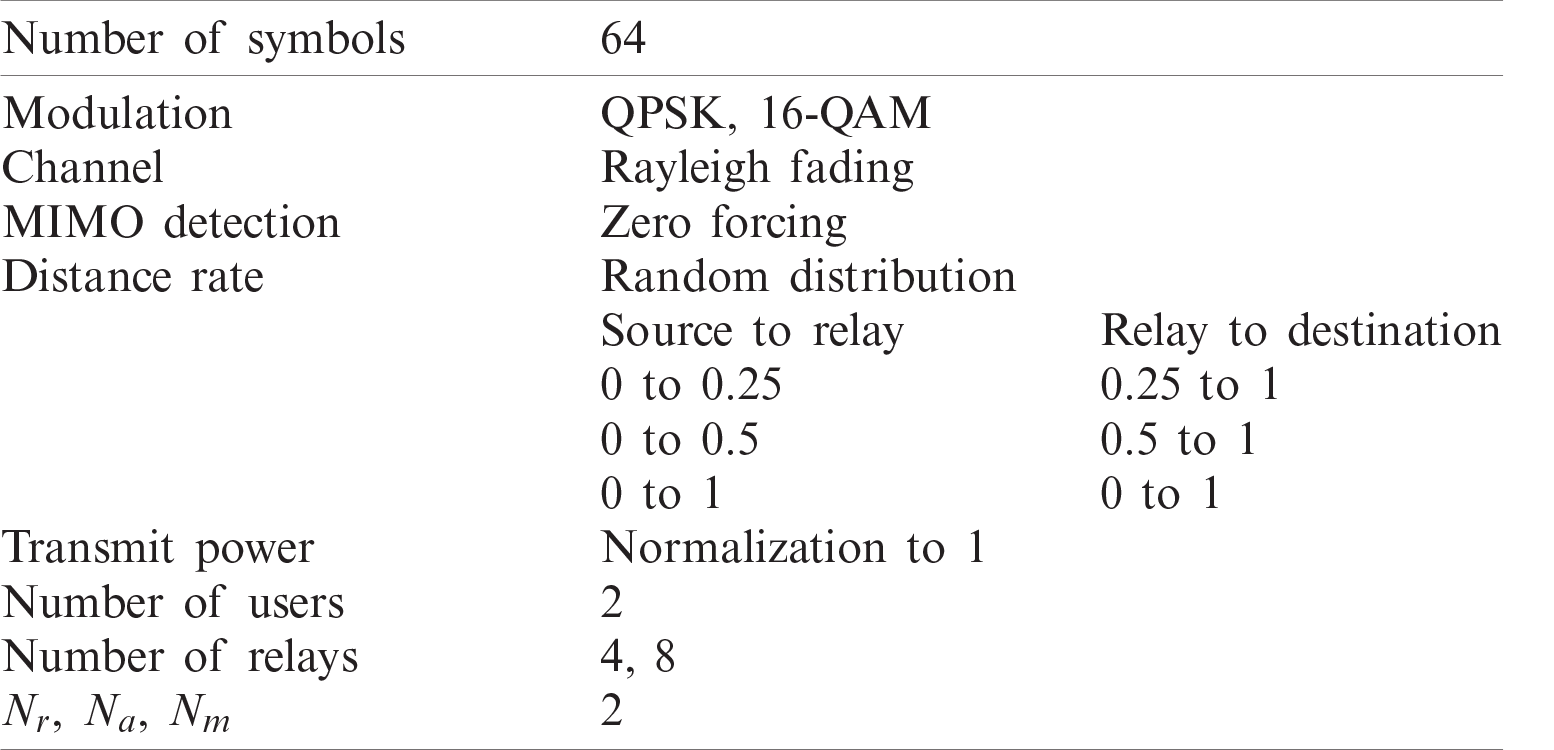
Tab. 1 shows the simulation parameters. The proposed scheme is simulated with 64 symbols and a 7-path Rayleigh fading channel. Two different modulation schemes of QPSK and 16-QAM are used to analyze the performance according to the modulation order. The zero-forcing (ZF) scheme is used to simplify signal detection. Three distance ranges are used to compare the performance effect of distance and outage. The first distance range is divided into
Table 1: Simulation parameters
The simulation graphs show the total transmission time and the maximum performance is normalized to 1. The proposed scheme is compared with the two conventional selection schemes, and the comparison schemes are mentioned in Section 3. The number of
In Fig. 4, the proposed scheme using QPSK modulation shows about 1.5 times faster performance at low SNR than the comparison scheme. At mid-SNR, the proposed scheme using QPSK modulation has about 1.3 times faster performance than the comparison scheme. As SNR increases, the occurrence of outages also decreases and the gain of time performance decreases. The proposed scheme using QAM modulation has about 1.5 times faster performance at low SNR. At mid-SNR, the proposed scheme using QAM modulation has about 1.3 times faster performance than the comparison scheme.
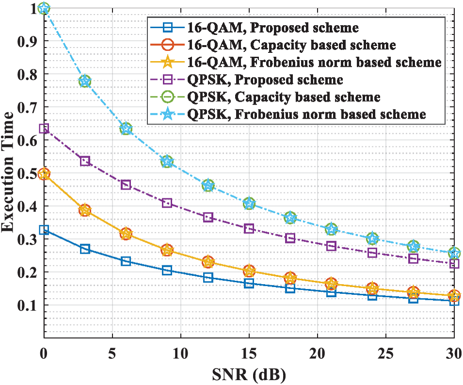
Figure 4: Total time performance (4 relays 0.25 distance)
In Fig. 5, the proposed scheme using QPSK modulation is about 1.3 times faster than the comparison scheme at low SNR. The proposed scheme using QAM modulation is about 1.15 times faster than the comparison scheme at low SNR. In the middle SNR, all performance gains are reduced between the proposed scheme and the comparison schemes. As the distance between the
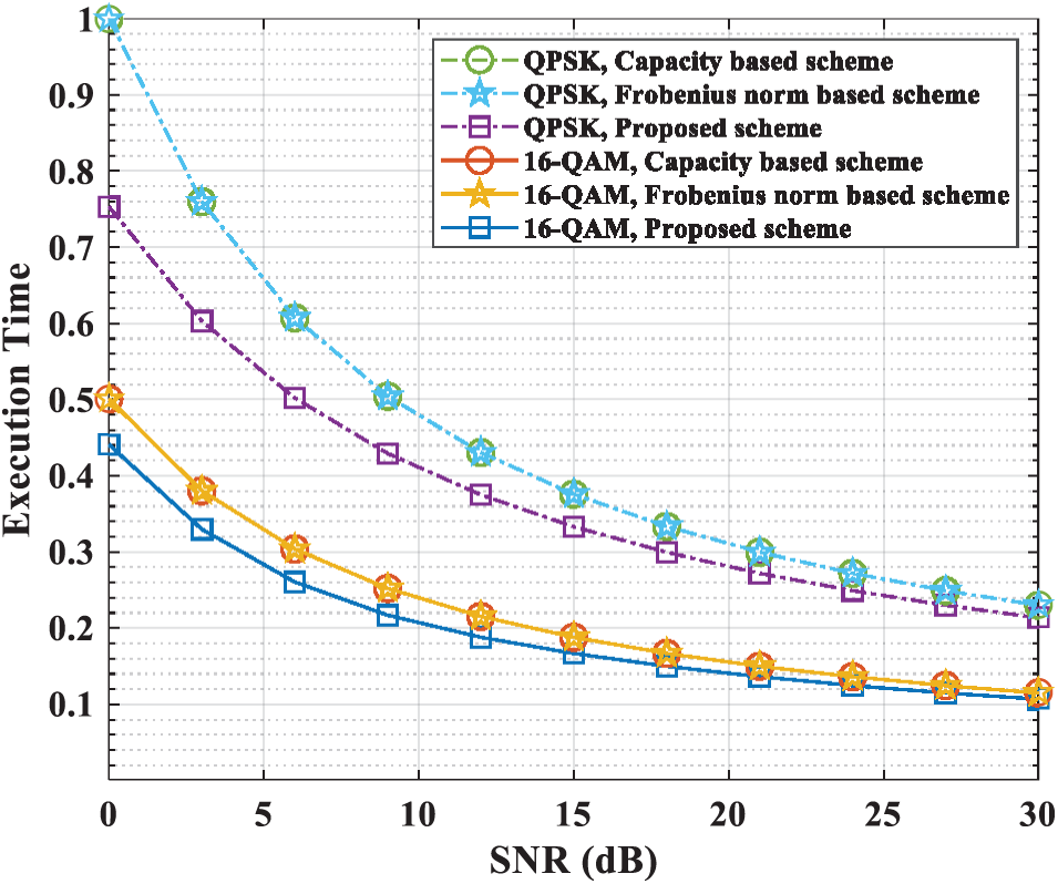
Figure 5: Total time performance (4 relays 0.5 distance)
Fig. 6 shows that the proposed scheme using QPSK modulation has 1.5 times faster performance gain than the comparison schemes of low SNR. At mid-SNR, the proposed scheme using QPSK modulation shows about 1.4 times faster than the comparison schemes. Compared to Fig. 5, the performance gain of the proposed scheme using QAM modulation is similar at low SNR, but increases at medium SNR. When a distance range is 1, the proposed scheme using QPSK modulation has performance improvement at low SNR.
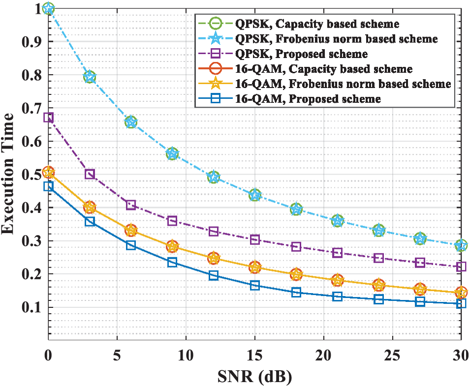
Figure 6: Total time performance (4 relays 1 distance)
All schemes in Figs. 4 and 7 have almost similar performance gain. Fig. 7 shows that the only proposed scheme has 1.2 times performance gain than the proposed scheme in Fig. 4. Although the number of
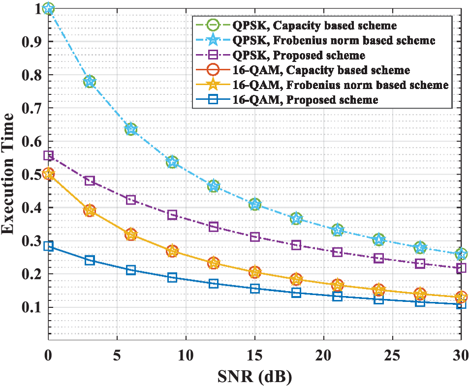
Figure 7: Total time performance (8 relays 0.25 distance)
In Fig. 9, the proposed scheme using QAM modulation is 1.3 times faster than the comparison schemes. The proposed scheme using QPSK modulation has 2 times performance improvement at low SNR than the comparison schemes. At mid-SNR, the proposed scheme using QPSK modulation has 1.8 times performance improvement at low SNR than the comparison schemes. The proposed scheme using QPSK modulation has 1.4 times performance improvement at low SNR compared to Fig. 6. At mid-SNR, the proposed scheme using QPSK modulation has 1.4 times performance improvement compared to Fig. 6. The performance of the proposed scheme using QAM modulation is similar to Fig. 6. The proposed scheme using QPSK modulation has a different form of performance gain than other Figures. With the QPSK modulation scheme, signal demodulation is easier than the QAM modulation scheme even when the outage occurs.
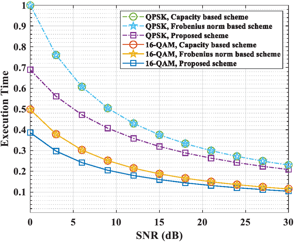
Figure 8: Total time performance (8 relays 5 distance)
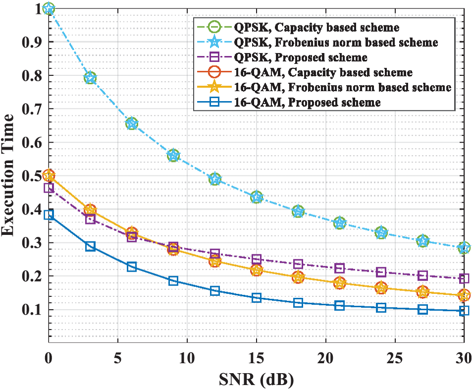
Figure 9: Total time performance (8 relays 1 distance)
The simulation results show that the proposed scheme reduces the performance of the total time than the comparison schemes. As the low SNR, the proposed scheme has higher performance gain. Depending on the distance range, the performance gain of the comparison schemes is same but the performance gain of the proposed scheme can be improved. Especially for distance ranges of 0.25 and 1, the proposed scheme has a performance gain. The performance gain can be increased with more users.
In this paper, a relay selection scheme is proposed for reducing the transmission time. The proposed scheme gets the performance gain from two steps. The available relays in the first step are classified as candidate relay group. According to the result of the first step, the second step is executed. When an applicable case exists, the second step determines a relay considering the transmission time of each user. Through this process, the proposed scheme shows that the total transmission time is improved even at low SNR. Simulation results show that the proposed scheme improves the total transmission time when the same data are transmitted.
Funding Statement: This research was supported by the MSIT (Ministry of Science and ICT), Korea, under the ITRC (Information Technology Research Center) support program (IITP-2019-2018-0-01423) supervised by the IITP (Institute for Information & communications Technology Promotion) and was supported by Basic Science Research Program through the National Research Foundation of Korea (NRF) funded by the Ministry of Education (2020R1A6A1A03038540).
Conflicts of Interest: The authors declare that they have no conflicts of interest to report regarding the present study.
1. Q. C. Li, H. Niu, A. T. Papathanassiou and G. Wu, “5G network capacity: Key elements and technologies,” IEEE Vehicular Technology Magazine, vol. 9, no. 1, pp. 71–78, 2014. [Google Scholar]
2. Liu, Y. Zhou, J. Yuan, W. Zhuang and Y. Wang, “Economically optimal MS association for multimedia content delivery in cache-enabled heterogeneous cloud radio access networks,” IEEE Journal on Selected Areas in Communications, vol. 37, no. 7, pp. 1584–1593, 2019. [Google Scholar]
3. S. Chen and J. Zhao, “The requirements, challenges, and technologies for 5G of terrestrial mobile telecommunication,” IEEE Communications Magazine, vol. 52, no. 5, pp. 36–43, 2014. [Google Scholar]
4. A. Krendzel, “LTE-A mobile relay handling: Architecture aspects,” in European Wireless 2013; 19th European Wireless Conf., Guildford, UK, pp. 1–6, 2013. [Google Scholar]
5. M. Pan, T. Lin and W. Chen, “An enhanced handover scheme for mobile relays in LTE-A high-speed rail networks,” IEEE Transactions on Vehicular Technology, vol. 64, no. 2, pp. 743–756, 2015. [Google Scholar]
6. H. Yasuda, A. Kishida, J. Shen, Y. Morihiro, Y. Morioka et al., “A study on moving cell in 5G cellular system,” in IEEE 82nd Vehicular Technology Conf., Boston, MA, pp. 1–5, 2015. [Google Scholar]
7. W. Li and M. Dong, “Joint relay beamforming and receiver processing for multi-way multi-antenna relay networks,” IEEE Transactions on Communications, vol. 66, no. 2, pp. 576–588, 2018. [Google Scholar]
8. D. Jiang, H. Zheng, D. Tang and Y. Tang, “Relay selection and power allocation for cognitive energy harvesting two-way relaying networks,” in 2015 IEEE 5th Int. Conf. on Electronics Information and Emergency Communication, Beijing, China, pp. 163–166, 2015. [Google Scholar]
9. H. Wang and B. Yang, “A new residual energy based relay selection in two-way buffer-aided relay networks,” in Int. Conf. on Network and Information Systems for Computers, Shanghai, China, pp. 72–76, 2017. [Google Scholar]
10. Y. Li, T. Wang, Z. Zhao, M. Peng and W. Wang, “Relay mode selection and power allocation for hybrid one-way/two-way half-duplex/full-duplex relaying,” IEEE Communications Letters, vol. 19, no. 7, pp. 1217–1220, 2015. [Google Scholar]
11. L. R. Ximenes, “Unified joint symbol and channel estimation with interference subtraction for one-way and two-way MIMO relaying systems,” in IEEE 10th Latin-American Conf. on Communications, Guadalajara, pp. 1–6, 2018. [Google Scholar]
12. Y. Wang, K. Xu, A. Liu and X. Xia, “Hybrid one-way full-duplex/two-way half-duplex relaying scheme,” IEEE Access, vol. 5, pp. 7737–7745, 2017. [Google Scholar]
13. M. Wen, X. Cheng and L. Yang, Index Modulation for 5G Wireless Communications. Cham, Switzerland: Springer International Publishing AG, 2017. [Google Scholar]
14. H. S. Ryu, J. S. Lee and C. G. Kang, “Relay selection scheme for orthogonal amplify-and-forward relay-enhanced cellular system in a multi-cell environment,” in IEEE 71st Vehicular Technology Conf., Taipei, Taiwan, pp. 1–5, 2010. [Google Scholar]
15. R. Narasimhan, “Spatial multiplexing with transmit antenna and constellation selection for correlated MIMO fading channels,” IEEE Transactions on Signal Processing, vol. 51, no. 11, pp. 2829–2838, 2003. [Google Scholar]
16. V. N. Q. Bao, N. Linh-Trung and M. Debbah, “Relay selection schemes for dual-hop networks under security constraints with multiple eavesdroppers,” IEEE Transactions on Wireless Communications, vol. 12, no. 12, pp. 6076–6085, 2013. [Google Scholar]
17. O. Semiari, W. Saad, M. Bennis and Z. Dawy, “Inter-operator resource management for millimeter wave multi-hop backhaul networks,” IEEE Transactions on Wireless Communications, vol. 16, no. 8, pp. 5258–5272, 2017. [Google Scholar]
18. L. Bononi and M. di Felice, “A cross layered MAC and clustering scheme for efficient broadcast in VANETs,” in IEEE Int. Conf. on Mobile Adhoc and Sensor Systems, Pisa, Italy, pp. 1–8, 2007. [Google Scholar]
19. H. A. Suraweera, M. Soysa, C. Tellambura and H. K. Garg, “Performance analysis of partial relay selection with feedback delay,” IEEE Signal Processing Letters, vol. 17, no. 6, pp. 531–534, 2010. [Google Scholar]
 | This work is licensed under a Creative Commons Attribution 4.0 International License, which permits unrestricted use, distribution, and reproduction in any medium, provided the original work is properly cited. |