DOI:10.32604/cmc.2021.014854
| Computers, Materials & Continua DOI:10.32604/cmc.2021.014854 | |
| Article |
ANN Based Novel Approach to Detect Node Failure in Wireless Sensor Network
1Faculty of Science and Technology, Universiti Sains Islam Malaysia, Nilai, 71800, Malaysia
2Advanced Informatics Department, Razak Faculty of Technology and Informatics, Universiti Teknologi Malaysia, Kuala Lumpur, 54100, Malaysia
3Department of ECE, Veltech Rangarajan Dr. Sagunthala R&D Institute of Science and Technology, 600062, Tamilnadu, India
4Department Electronics & Communication Engineering, Birla Institute of Technology, Mesra, Jharkhand, India
5Faulty of Information Technology, University of Technology and Applied Sciences, Muscat, 133, Oman
6College of Computing and Information Technology, University of Bisha, Bisha, 67714, Saudi Arabia
*Corresponding Author: Suresh Ponnan. Email: suresh3982@yahoo.co.in
Received: 22 October 2020; Accepted: 29 January 2021
Abstract: A wireless sensor network (WSN) consists of several tiny sensor nodes to monitor, collect, and transmit the physical information from an environment through the wireless channel. The node failure is considered as one of the main issues in the WSN which creates higher packet drop, delay, and energy consumption during the communication. Although the node failure occurred mostly due to persistent energy exhaustion during transmission of data packets. In this paper, Artificial Neural Network (ANN) based Node Failure Detection (NFD) is developed with cognitive radio for detecting the location of the node failure. The ad hoc on-demand distance vector (AODV) routing protocol is used for transmitting the data from the source node to the base station. Moreover, the Mahalanobis distance is used for detecting an adjacent node to the node failure which is used to create the routing path without any node failure. The performance of the proposed ANN-NFD method is analysed in terms of throughput, delivery rate, number of nodes alive, drop rate, end to end delay, energy consumption, and overhead ratio. Furthermore, the performance of the ANN-NFD method is evaluated with the header to base station and base station to header (H2B2H) protocol. The packet delivery rate of the ANN-NFD method is 0.92 for 150 nodes that are high when compared to the H2B2H protocol. Hence, the ANN-NFD method provides data consistency during data transmission under node and battery failure.
Keywords: AODV; artificial neural network; artificial intelligence; Mahalanobis distance; node failure; throughput; wireless sensor network
Wireless Sensor Networks (WSNs) contain several tiny sensor nodes which have the capacity of sensing, processing, and transferring the data through the wireless channels [1,2]. The WSN sensor nodes include many components such as power supply, microcontrollers, communication devices and sensors [3]. These spatially distributed sensors are utilized for observing the physical conditions of an environment such as vibration, temperature, pressure, and other parameters. These sensed information are transmitted to the Base Station (BS) via cluster heads (CHs), while BS can be used to link one network to another [4–6]. WSNs commonly used in a wide range of applications including health care, security, monitoring environment, home applications, industry, and military [7]. These applications require Quality of Service (QoS) centric, fault resilient, consistence and reliable communications over a wireless medium [8]. However due to small size the wireless nodes have several constraints such as inadequate computational capability, power, link bandwidth, and low storage [9].
A sensor node is responsible for sensing and transmitting the data either to its respective cluster heads (CHs) or to another sensor node. Before the transition of data to the BS, CHs carried out data aggregation and data fusion operations. CHs keeps the data inside RAM or Flash drive. RAM capacity is quite limited from 1 KB to 32 MB and contains data for transmission purposely only. When the data is delivered to a BS, nodes or CHs will have no backup of transmitted packets. RAM has the benefit of easy entry, but when power is disrupted it loses contents. The read-only memory serves to hold the software code of the microprocessor that transmits and collects the sensor node and other resources. In case the RAM is inadequate, or the power supply shut down, the Flash may also act as the intermediate storage of data. Memory capacity depends on the capabilities and software of the sensor microcontroller processing. The software and hardware malfunctions, battery failure, and environmental effects create nodes failure related issues in WSNs. Hence, the data from the faulty sensors are discarded to obtain a better quality of service (QoS) in WSNs [10,11]. The data transmission in the WSN is complicated due to link susceptibility caused by the various errors and faults. However, nodes failure issues create significant packets loss which results in higher network delay and energy consumption [12]. Therefore, efficient clustering and routing algorithms are developed to improve the WSN performances. In the clustering process, the sensor nodes are clustered, and each cluster has a leading node known as Cluster Head (CH) which is used for data aggregation from its cluster members and to discard the unwanted data and uncorrelated data. It also allows to control the redundancy of data packets used to minimize the node energy usage [13,14]. Furthermore, the multi-hop routing protocol is used to transmit the information to the BS or sink node [15].
The major contributions of this research paper are given as follows:
• The enhanced Ad hoc On-Demand Distance Vector (AODV) Routing protocol is used to transmit the information from the source (CHs) to the BS.
• An artificial neural network-based node failure detection is proposed to minimize the packets drop ratio across the network which is called as ANN-NFD. This node failure detection is used to obtain data consistency while transmitting the data packets from the source to the destination.
• The Mahalanobis distance is used to detect the adjacent node for the node failure to replace it during the data transmission.
The overall organization of the paper is given as follows: The literature survey about the existing methods of fault detection in the WSN is given in Section 2. The proposed ANN-NFD method for detecting and replacing node failure during data transmission is clearly described in Section 3. The results and discussion for the ANN-NFD method are given in Section 4. Finally, the conclusion is made in Section 5.
Moussa et al. [16] presented the cluster-based fault tolerant routing protocol namely CFTR for selecting the CH with higher energy. The energy efficiency was improved by using the cost function which considered the cost of energy from the sensor node to CH and CH to BS, and the number of clusters in the previous round. The cost function was used to select the next-hop node for the CH as well as it is used to select the optimum routing path with adequate energy. Additionally, this cost function was used to obtain a uniform data transmission between all CHs. The rapid failure of CHs was tolerated by using the lightweight and low-overhead algorithm.
Riaz et al. [17] developed the Fast-Rerouting Protocol (FRP) to generate the primary and backup routes through the network. This FRP has generated at least one backup path along with the primary path between the source to the destination. The data transmission was initialized, only when the primary and backup paths are created during the path generation phase. The developed FRP has the capacity for handling the many failures in mission critical WSN.
Yue et al. [18] presented the fault-tolerant routing algorithm by combining the Artificial Bee Colony (ABC) and Particle Swarm Optimization (PSO). The path failure caused by the movable sink was overcome based on the faster rerouting obtained by the ABC-PSO algorithm. Moreover, the fitness node collections were improved for generating the path with the best fitness value. The local optimum convergence of ABC-PSO was avoided by improving the exploration and optimization capacity. The reliability and fault tolerance were improved by enhancing operational efficiency and response abilities.
Yuvaraja et al. [19] developed the fault detection and recovery scheme to improve the lifetime of the WSN. The BS has generated an agent packet and the agent has created the query path to the dead/ faulty node. The BS has frequently transmitted the agent packet to the adjacent nodes of the network. The random decision was taken about data transmission when the TTL field contains a nonzero in the Agent packet. Else the node is declared as a dead and faulty node during the communication. Therefore, the Least-Disruptive Topology Repair (LeDiR) was used to restore the routing path when the failure was detected in the path. moreover, this LeDiR has generated the routing path without extending the length of the shortest path.
Krishnan et al. [20] presented the Header to base station and base station to header (H2B2H) protocol for addressing the link failure among the 2 header nodes in the WSN. The H2B2H protocol was automatically accomplished when there is link failure between the predecessor CH and successor CH. The predecessor CH was transmitted the data to the BS, based on the H2B2H protocol. Here, the BS had the information about all nodes of the network and the BS had the responsibility to forward the data to the desired destination. However, the H2B2H protocol was required to do network partition during failure and it failed to handle multiple link failures through the WSN.
3 System Model and Methodology
The description of the network model and energy model considered in the ANN-NFD method are described in this section.
A large number of sensor nodes were randomly deployed in the required area of WSN. The network model has different assumptions which are mentioned as follows:
• The BS and nodes are static once it is deployed in the network.
• The nodes in the network are aware of their location and the nodes are homogeneous.
• Received signal strength is used to compute the distance from the sensor the BS.
• Dead node is caused due to energy exhaustion.
• The sensor node’s transmission power is varied based on the distance from the receiver node.
The Network Simulator (NS-2) is utilized to design and simulate the cognitive radio-based WSN. This NS-2 is used to obtain the simulation about the sensing, processing, and transmitting the data packets by using the wireless nodes. Here the code is generated using C++ and OTCL script for simulating the wireless communication.
In the ANN-NFD method, the simplified first-order radio model is used as an energy model. The amount of energy consumed while transmitting the receiving (l) number of packets over the distance (d) are expressed in the Eqs. (1) and (2) respectively.
where, Eelec represents the amount of energy dissipated by the transmitter and receiver;
In this ANN-NFD method, an ANN-based detection with cognitive radio is used for detecting the nodes failure in the WSN. The data transmission between the source nodes to the BS is obtained by using the AODV routing protocol. If the routing protocol has the node failure during communication, the adjacent node of node failure will be replaced for achieving a reliable data transmission. The adjacent node is detected by using the Mahalanobis distance. The main steps processed in this ANN-NFD method are given as follows:
• At first, the sensor nodes are randomly deployed in the network. Then the information about the sensor nodes i.e., positions are given as input to the AODV routing protocol.
• The AODV routing protocol is used to identify the possible path from the source node to the BS based on the route request and route reply messages.
• Next, the ANN is used to detect the node failures in the routing path. The packet loss of the nodes considered in the ANN for detecting the node failure.
• If the generated routing path from the AODV has node failure, the Mahalanobis distance is used to identify the adjacent normal node. Subsequently, the adjacent node is replaced instead of the node failure.
• Finally, the data transmission takes place from the source node to the destination (i.e., BS).
The flowchart of the ANN-NFD method is shown in Fig. 1.
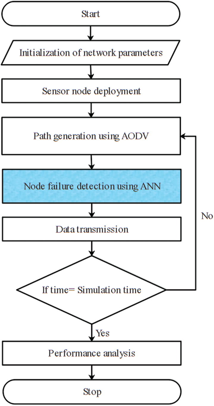
Figure 1: Flowchart of the ANN-NFD method
WSN is considered with a huge amount of tiny sensor nodes which is randomly distributed in the network area. The main component of the WSN includes sensor nodes and gateway nodes which are placed in a static environment. The fault type identified in this ANN-NFD method is node failure occurred in the network.
Node Failure
The node failure is the condition when the node is passive to messages from other nodes. Generally, the failure of a node happens in a different manner such as battery power drain, hardware defects and software failure. This node failure causes the routing overhead and creates packets to drop or corrupt the data packets. Therefore, node failure affects the performances of the network.
The capacity of the cognitive radio is the detection of the unused spectrum in a licensed and unlicensed spectrum band of the sensor nodes. The nodes in the cognitive radio are categorized into two types such as primary and secondary nodes. The node which requires the spectrum uses the unused spectrum of the remaining nodes of the WSN. In cognitive radio based WSN, the primary nodes use the spectrum at any time during the communication, whereas the secondary nodes use the spectrum only when the primary nodes are not using the spectrum over the network. Here, the spectrum sensing is performed by collecting the information about the secondary nodes by using the primary nodes. Next, the AODV based route generation is used for transmitting the data from the primary nodes to the destination. But the spectrum sensing is accomplished when the secondary nodes are required to transmit the data through the network. Here, AODV based route generation is used for both the primary and secondary nodes.
In the ANN-NFD method, the AODV is used to identify the route for the primary and secondary nodes. Generally, AODV is a combination of two different routing protocols such as DSDV and DSR. The route discovery and maintenance of DSR are integrated with the hop and routing of DSDV to develop the AODV routing protocol. Moreover, this AODV routing protocol also could be used for mobile nodes and determines the routing path in the dynamic network. The essential features of the AODV routing protocol are lower network load, lower computation power, and faster access speed. Moreover, the infinite counting issues and network loop are avoided by using the destination sequence number field in the AODV protocol. There are three important message mechanism are used in the AODV routing protocol such as route request (RREQ), route reply (RREP), and routing error (RERR).
Route Discovery Using AODV
At first, the source node verifies the routing table whether it has any routing path to the destination node (BS) or not. The source node transmits the data packets when the source node has a routing path to the destination node. Otherwise, the RREQ message is transmitted to the adjacent nodes in the network for identifying the transmission path. For example, the distribution of the RREQ message from the source node is illustrated in Fig. 2. Subsequently, the intermediate node and BS transmit the RREP message to the source node in the AODV route discovery process. The transmission of the RREP message is carried out over the reverse route identified in the route discovery process. In the RREQ message, the serial number of the source node is utilizing for maintaining the reverse route to the source node. Each node in the network automatically generates the reverse route to the source node when the source node transmits the RREQ message to the various destination node. Next, the sensor node creates the neighbor node’s address for the first RREQ message. In AODV routing, the reverse routing is maintained for a certain time to the source node. The destination node generated the RREP packet when it receives the RREQ message from the source node and the generated RREP packet is transmitted through the reverse routing path. Fig. 2 shows the illustration of the source node receives the RREP message from the BS. Therefore, the routing path between the source node to the BS is generated, once the RREP is received by the source node. The path information obtained from the AODV routing protocol is given as the input to the ANN-based node failure detection for reliable data transmission.
4.4 Detection of Node Failure Using ANN
In this ANN-NFD method, ANN is used to detect the node failure for improving the data consistency of the WSN. The ANN considers the packets loss to detect the node failure between all nodes of the network.
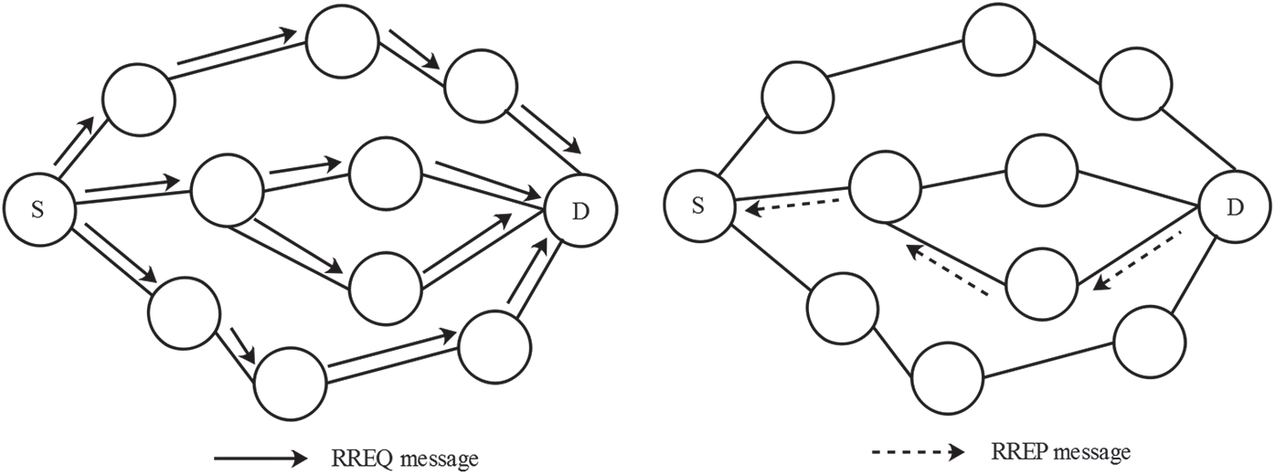
Figure 2: Transmission of RREQ message and route identification using RREP message
ANN is generally designed by using the interconnected neurons which process the given input for delivering the desired solution. Consider, m is the number of inputs
The function in Eq. (4) returns either 1 or 0 while processing the inputs. The nonlinear and complex issues are solved by using the back-propagation algorithm in ANN. The calculation of error between the input and output layer is used to accomplish the operation of the back-propagation algorithm. Moreover, the weights are updated by propagating the errors to the previous layer. The gradient descent G is used to back-propagate the value and this G is the derivation of the activation function (f). The error is reduced with each iteration of the process and the output becomes closer to the desired output which is shown in Eq. (5). Next, the value of gradient descent is shown in Eq. (6).
The activation function used in the ANN is the sigmoid/logistic function which is shown in the Eq. (7) as well as expression to update the weight is shown in Eq. (8).
where the momentum rate is represented as
4.4.2 ANN Base Node Failure Detection
The ANN used for the failure node detection is shown in Fig. 3 and this ANN architecture utilizes three layers such as input layer, hidden layer, and output layer. The input given to the input layer neuron is packet loss caused by the nodes. The nodes in the output layer produce the state of sensor nodes like normal nodes or node failure.
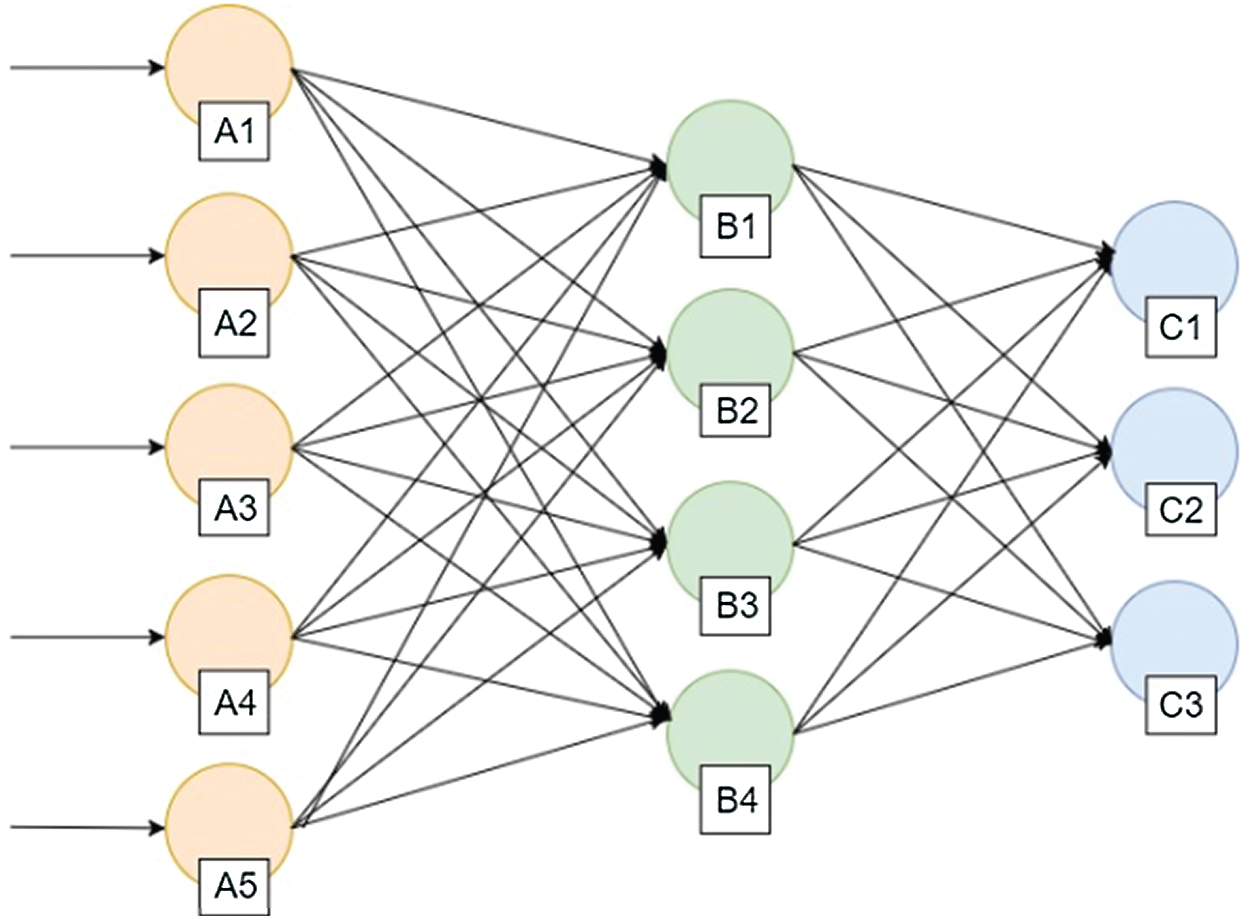
Figure 3: Architecture ANN
The number of dropped packets from all nodes of the WSN is given as the input vector for training the network. The sensor nodes and packet drop data are labelled and given to the ANN as inputs. The difference between the normal sensor nodes and node failure is obtained during the testing phase of the ANN. The identification of node failure in the network is illustrated in Fig. 4.
4.5 Node Failure Management in Data Transmission
The information about node failure is used to identify whether the generated route of AODV has node failure or not. The source node transmits the data packets to the BS when the route does not have any node failure. Otherwise, the Mahalanobis distance is used to detect the adjacent node to the node failure. Next, the detected adjacent node is considered in the routing path instead of the node failure as shown in Fig. 5. The formulae for the Mahalanobis distance are expressed in Eq. (9).
where,
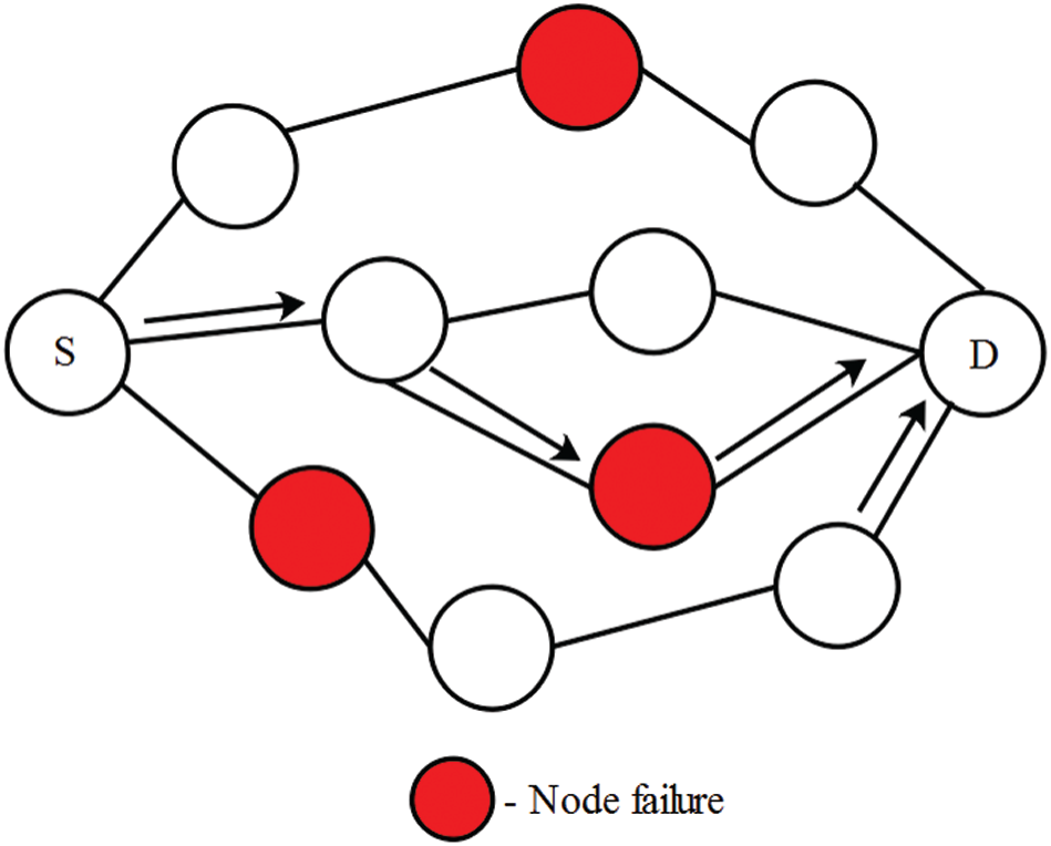
Figure 4: Identification of node failure using ANN
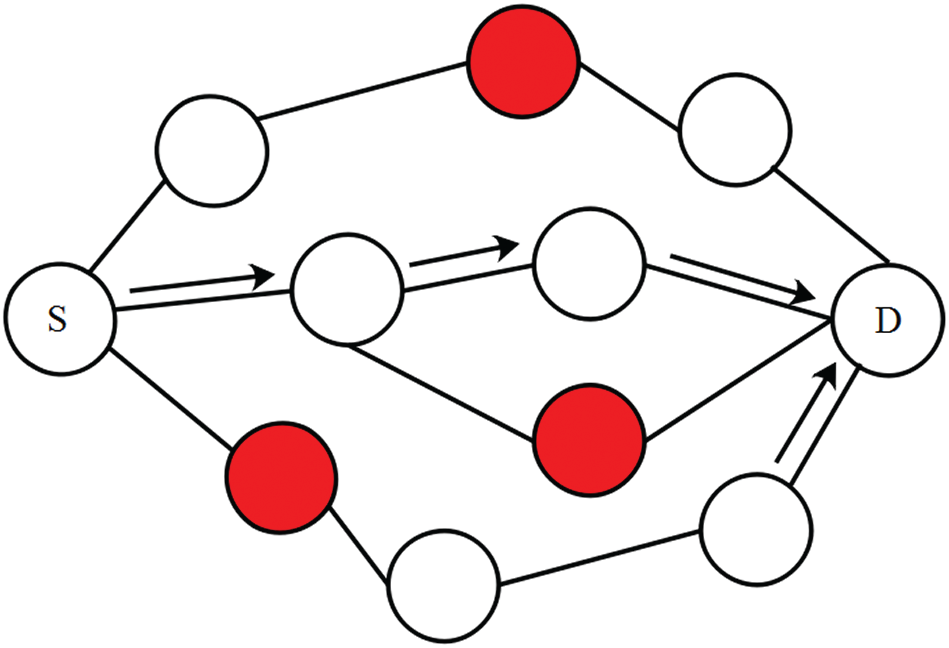
Figure 5: Node failure management
The experimental results and discussion of the ANN-NFD method clearly described in this section. The implementation and simulation of this ANN-NFD method with cognitive radio are carried out by using the Network Simulator (NS) 2.35 which is operated in a Windows 8 operating system with an Intel Core i3 processor and 4 GB RAM.
In this ANN-NFD method, the node failure is detected and avoided while transmitting the data packets using the AODV protocol. Here, the Mahalanobis distance is used to detect the adjacent node to the node failure. This ANN-NFD method is analysed with 100-600 sensor nodes which are deployed around 1000 m
The overall network topology and nodes failure identification in NS 2 software is illustrated in Fig. 6. The performances of the ANN-NFD method are analysed in terms of throughput, delivery rate, number of alive nodes, drop rate, End to End Delay (EED), energy consumption, and overhead ratio. Here, the ANN-NFD method is compared with the H2B2H protocol to evaluate the efficiency of the ANN-NFD method.
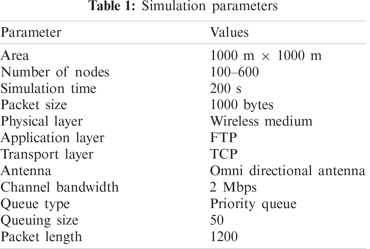
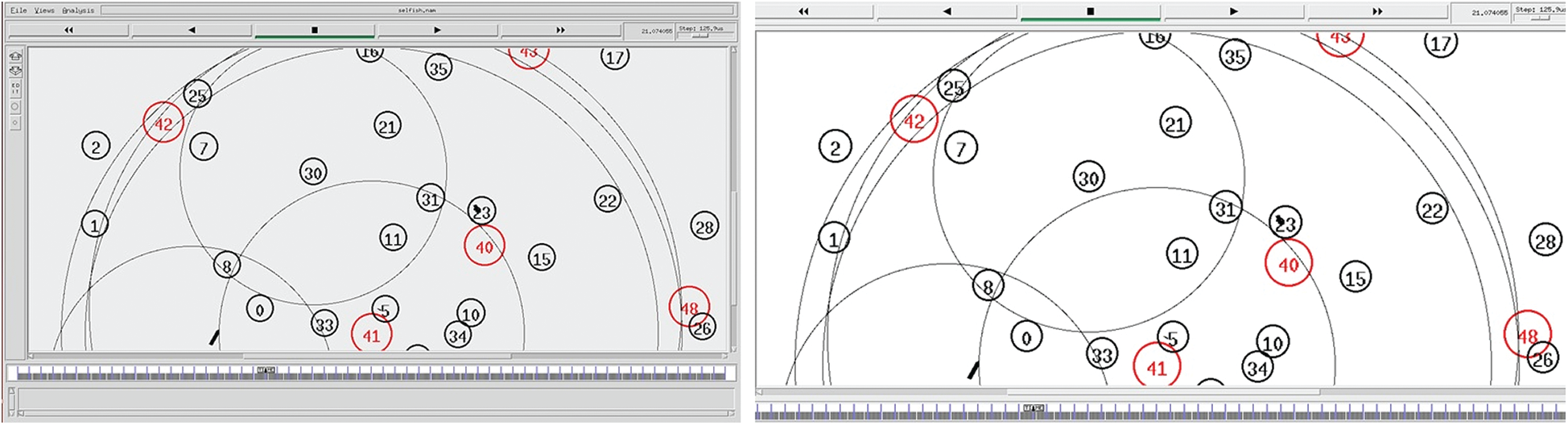
Figure 6: Overall network topology and node failure identification using ANN
Throughput is defined as the number of data packets received by the BS during the simulation time. The throughput is expressed as bits per second expressed in Eq. (10).
where, Qi is the number of packets received by the BS and t is the simulation time.
Fig. 7 shows the performance comparison of throughput for the ANN-NFD with H2B2H in terms of varying nodes. From Fig. 7, knows that the ANN-NFD has higher throughput when compared to the H2B2H. The node failure management of ANN-NFD is helping to transmit a high number of data packets to the BS. But the H2B2H does not consider the multiple link failure during the communication, it causes less throughput.
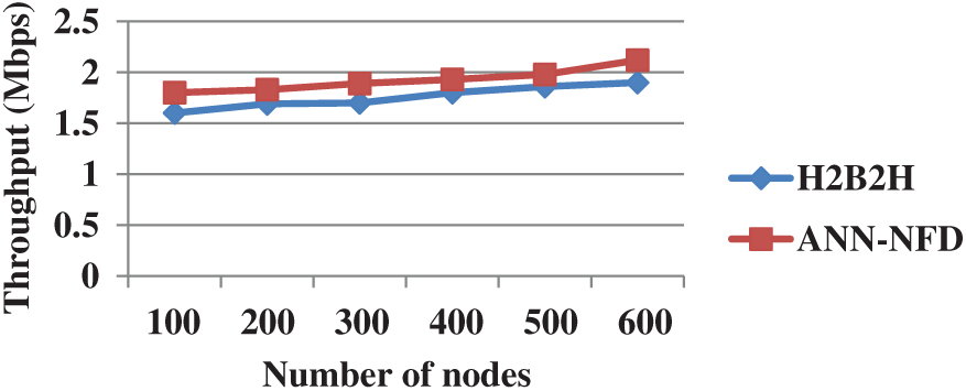
Figure 7: Performance comparison of throughput
Packet Delivery rate [21] is defined as the ratio between the total data packets received by the BS and the total data generated in the source node. Eq. (11) shows the expression for the delivery rate.
where the number of experiments is represented as M; the number of source node transmitting the data packets is represented as n; the number of packets transmitted by the source node and the number of packets received by the BS are represented as Pi and Qi respectively.
The performance comparison of delivery rate in terms of network size for ANN-NFD with H2B2H is shown in Fig. 8. From Fig. 8, knows that the delivery rate of the ANN-NFD method is high when compared to the H2B2H. A higher delivery rate is obtained by avoiding the node failure in the routing path. Because the node failure in the routing path creates the packet loss.
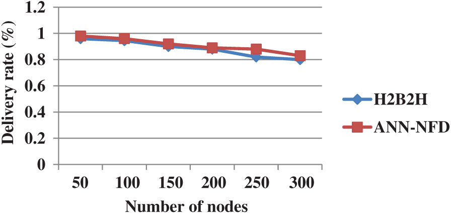
Figure 8: Performance comparison of packets delivery rate
The sensor node with enough energy for data transmission is referred to as alive nodes which are used to evaluate the network lifetime.
Fig. 9 shows the performance comparison of alive nodes for the ANN-NFD with H2B2H in terms of simulation time. The ANN-NFD has higher alive nodes than the H2B2H as shown in Fig. 9. The multiple link failure in the H2B2H protocol creates an energy depletion for the sensor nodes in the WSN. This leads to a drain of the sensor node’s energy and it increases the number of dead nodes through the network. But the ANN-NFD is developed to handle multiple node failures during the communication, which enhances the energy consumption.
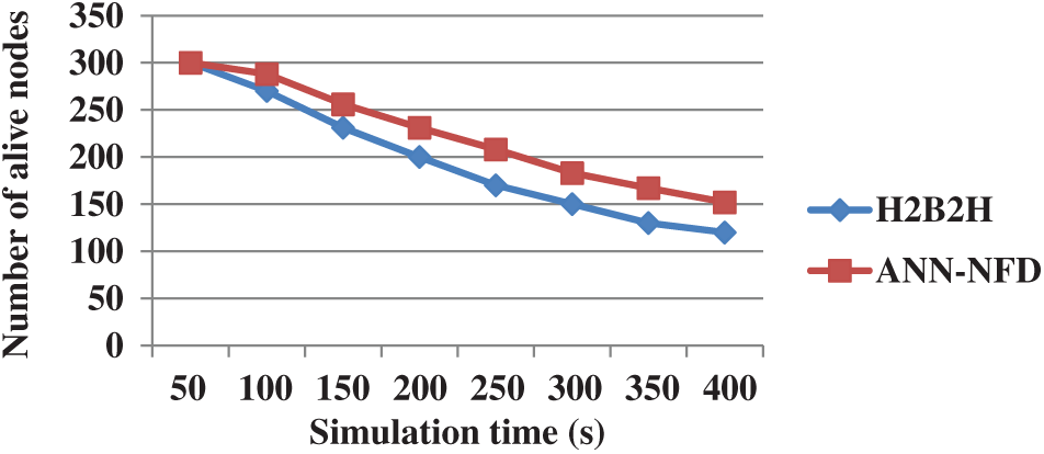
Figure 9: Performance comparison of alive node
Packet Drop Rate is defined [22] as the ratio between the total number of dropped packets and the total number of generated packets by the source node. The drop rate is expressed in the following Eq. (12).
The performance comparison of drop rate in terms of network size for ANN-NFD with H2B2H is shown in Fig. 10. The drop rate of the ANN-NFD method is less when compared to the H2B2H protocol. The control over the multiple node failures in ANN-NFD is used to avoid the packets drop ratio in the network. Therefore, the packets drop of the ANN-NFD method is significantly minimized by reducing the packets drop.
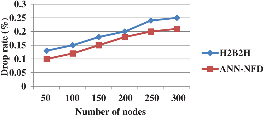
Figure 10: Performance comparison of packet drop ratio
The amount of time taken to transmit the data from the source node to the BS is specified as EED that is shown in Eq. (13). Here, two different metrics are used to calculate the EED that are the sent time (st) and the arrival time (at).
Fig. 11 shows the performance comparison of EED for ANN-NFD with H2B2H in terms of simulation time. The EED of the ANN-NFD method is less when compared to the H2B2H. The main reason for the ANN-NFD method with less EED is that it does not need any rerouting during the node failure. But the H2B2H protocol is required to do network partition when the failure occurs in the WSN.
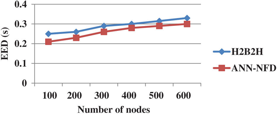
Figure 11: Performance comparison of EED
Energy consumption of the WSN is defined as the amount of energy utilized to transmit and received the data packets through the network.
The performance comparison of energy consumption in terms of simulation time for ANN-NFD with H2B2H is shown in Fig. 12. From Fig. 12, knows that the ANN-NFD has lesser energy consumption than the H2B2H. The energy consumption of the nodes of ANN-NFD is minimized by avoiding the multiple node failures in the WSN. This leads to improving the lifetime of the network.
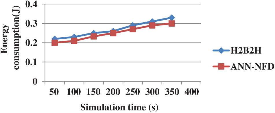
Figure 12: Performance comparison of energy consumption
The number of control packets generated in the WSN is defined as routing overhead that is shown in Eq. (14).
where the number of control packets generated in the WSN is represented as Ci.
Fig. 13 shows the performance comparison of routing overhead for ANN-NFD with H2B2H in terms of varying nodes. The routing overhead of the ANN-NFD is less when compared to the H2B2H. The less routing overhead is obtained by replacing the node failure with an adjacent node which is detected by using the Mahalanobis distance.
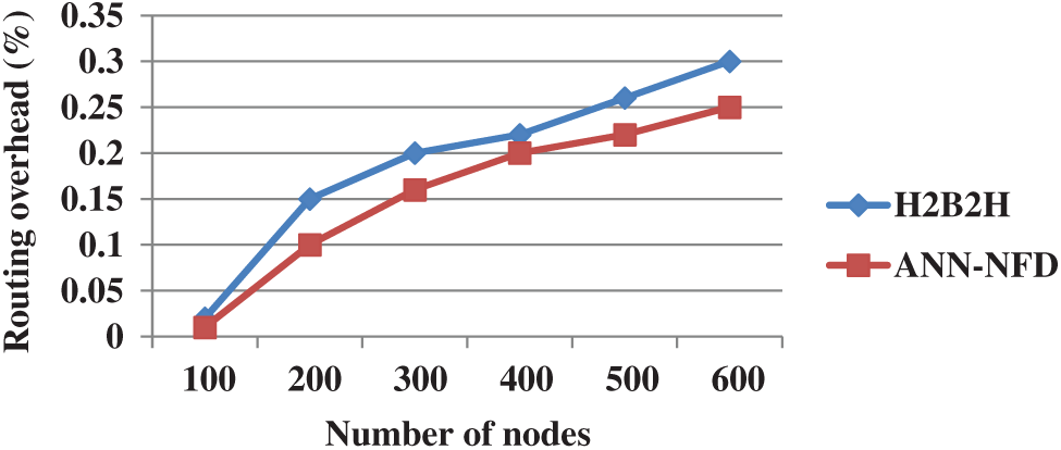
Figure 13: Performance comparison of routing overhead
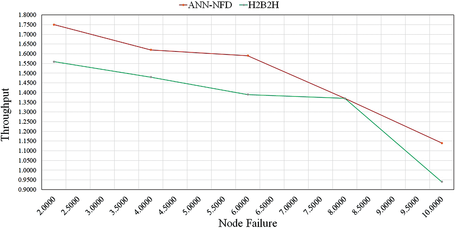
Figure 14: Performance comparison of throughput under node failure
5.8 Throughput Analysis for Node Failure
The performance comparison of throughput for ANN-NFD with H2B2H under node failure is shown in Fig. 14. The throughput of the ANN-NFD method is high when compared to the H2B2H. The H2B2H protocol failed to handle the multiple link failure that created packet loss in the network. Due to the node failure detection of the ANN-NFD method, the throughput is increased while transmitting the data packets.
In this paper, the AODV routing protocol is used for transmitting the data packets to the BS. The packet drop caused by the entire node of the network is given as input to the ANN with cognitive radio for detecting the node failures in the WSN. The location of node failures is used in the phase of node failure management for replacing the node failure with normal nodes. This ANN-NFD is used to handle multiple node failures during communication. The energy consumption and packet drop significantly improved by avoiding the node failure in the routing path. From the analysis, knows that the ANN-NFD method achieves better performance than the H2B2H protocol. The energy consumption of the ANN-NFD method is 0.21J for 100 nodes, it is less when compared to the H2B2H protocol.
Acknowledgement: We thanks USIM to give us the opportunity for this research work.
Funding Statement: The authors received no specific funding for this study.
Conflicts of Interest: The authors declare that they have no conflicts of interest to report regarding the present study.
1. M. Tabassum, S. Perumal and A. H. Halim, “Review and evaluation of data availability and network consistency in wireless sensor networks,” Malaysian Journal of Science, Health & Technology, vol. 4, Special Issue (KoSIST 2018pp. 1–8, 2019. [Google Scholar]
2. M. Tabassum and K. Zen, “Performance evaluation of ZigBee in indoor and outdoor environment,” in 9th Int. Conf. on IT in Asia, Kuching, Malaysia, pp. 1–7, 2015. [Google Scholar]
3. S. Arjunan and P. Sujatha, “Lifetime maximization of wireless sensor network using fuzzy based unequal clustering and ACO based routing hybrid protocol,” Applied Intelligence, vol. 48, no. 8, pp. 2229–2246, 2018. [Google Scholar]
4. M. Tabassum and K. Zen, “Signal interference evaluation of Eko wireless sensor network,” in 19th Int. Conf. on Transformative Research in Science and Engineering, Business and Social Innovation, Kuching, Malaysia, pp. 1–12, 2014. [Google Scholar]
5. K. Haseeb, K. A. Bakar, A. Ahmed, T. Darwish and I. Ahmed, “WECRR: Weighted energy-efficient clustering with robust routing for wireless sensor networks,” Wireless Personal Communications, vol. 97, no. 1, pp. 695–721, 2017. [Google Scholar]
6. S. Singh, A. Malik and R. Kumar, “Energy efficient heterogeneous DEEC protocol for enhancing lifetime in WSNs,” Engineering Science and Technology an International Journal, vol. 20, no. 1, pp. 345–353, 2017. [Google Scholar]
7. C. Chakraborty, B. Gupta and S. K. Ghosh, “A review on telemedicine-based WBAN framework for patient monitoring,” International Journal of Telemedicine and e-Health, vol. 19, no. 8, pp. 619–626, 2013. [Google Scholar]
8. D. R. Ganesh, K. K. Patil and L. Suresh, “Q-FRPML: QoS-centric fault-resilient routing protocol for mobile-WSN based low power lossy networks,” Wireless Personal Communications, vol. 105, no. 1, pp. 267–292, 2019. [Google Scholar]
9. N. X. Tien, S. Kim, J. M. Rhee and S. Y. Park, “A novel dual separate paths (DSP) algorithm providing fault-tolerant communication for wireless sensor networks,” Sensors, vol. 17, no. 8, pp. 1699, 2017. [Google Scholar]
10. R. N. Duche and N. P. Sarwade, “Sensor node failure detection based on round trip delay and paths in WSNs,” IEEE Sensors Journal, vol. 14, no. 2, pp. 455–464, 2013. [Google Scholar]
11. K. Rajeswari and S. Neduncheliyan, “Genetic algorithm-based fault tolerant clustering in wireless sensor network,” IET Communications, vol. 11, no. 12, pp. 1927–1932, 2017. [Google Scholar]
12. S. Abba and J. A. Lee, “An autonomous self-aware and adaptive fault tolerant routing technique for wireless sensor networks,” Sensors, vol. 15, no. 8, pp. 20316–20354, 2015. [Google Scholar]
13. M. Tabassum and K. Zen, “Evaluation and improvement of data availability in WSNs cluster base routing protocol,” Journal of Telecommunication, Electronic and Computer Engineering, vol. 9, no. 2, pp. 111–116, 2017. [Google Scholar]
14. T. Kaur and D. Kumar, “Particle swarm optimization-based unequal and fault tolerant clustering protocol for wireless sensor networks,” IEEE Sensors Journal, vol. 18, no. 11, pp. 4614–4622, 2018. [Google Scholar]
15. M. El Fissaoui, A. Beni-Hssane and M. Saadi, “Energy efficient and fault tolerant distributed algorithm for data aggregation in wireless sensor networks,” Journal of Ambient Intelligence and Humanized Computing, vol. 10, no. 2, pp. 569–578, 2019. [Google Scholar]
16. N. Moussa, El Belrhiti and A. El Alaoui, “A cluster-based fault-tolerant routing protocol for wireless sensor networks,” International Journal of Communication Systems, vol. 32, no. 16, pp. 4131, 2019. [Google Scholar]
17. S. Riaz, M. Rehan, T. Umer, M. K. Afzal and W. Rehan, “FRP: A novel fast rerouting protocol with multi-link-failure recovery for mission-critical WSN,” Future Generation Computer Systems, vol. 89, pp. 148–165, 2018. [Google Scholar]
18. Y. Yue, L. Cao, B. Hang and Z. Luo, “A swarm intelligence algorithm for routing recovery strategy in wireless sensor networks with mobile sink,” IEEE Access, vol. 6, pp. 67434– 67445, 2018. [Google Scholar]
19. M. Yuvaraja and M. Sabrigiriraj, “Fault detection and recovery scheme for routing and lifetime enhancement in WSN,” Wireless Networks, vol. 23, no. 1, pp. 267–277, 2017. [Google Scholar]
20. R. Krishnan and G. Perumal, “H2b2h protocol for addressing link failure in WSN,” Cluster Computing, vol. 22, no. 4, pp. 9687–9696, 2019. [Google Scholar]
21. C. Chakraborty, R. Roy, S. Pathak and S. Chakrabarti, “An optimal probabilistic traffic engineering scheme for heterogeneous networks,” CIIT International Journal of Fuzzy Systems, vol. 3, no. 2, pp. 35–39, 2011. [Google Scholar]
22. T. Sharma and M. Tabassum, “Enhanced algorithm to optimize QoS and security parameters in ad hoc networks,” in Design Methodologies and Tools for 5G Network Development and Application, IGI Global, pp. 1–27, 2021. [Google Scholar]
 | This work is licensed under a Creative Commons Attribution 4.0 International License, which permits unrestricted use, distribution, and reproduction in any medium, provided the original work is properly cited. |