DOI:10.32604/cmc.2021.018743
| Computers, Materials & Continua DOI:10.32604/cmc.2021.018743 | |
| Article |
Leader-Follower UAV Formation Model Based on R5DOS-Intersection Model
1College of Information Technology, Jilin Agricultural University, Changchun, 130118, China
2College of Electricity and Information, Changchun Guanghua University, Changchun, 130033, China
3Bioinformatics Research Center of Jilin Province, Changchun, 130118, China
4Department of Mathematical Sciences, Delaware State University (DSU), Dover, 19901, DE
*Corresponding Author: Xiaoguang Li. Email: 843973603@qq.com
Received: 19 March 2021; Accepted: 03 May 2021
Abstract: This paper proposes a formation of multiple unmanned aerial vehicles (UAVs) based on the R5DOS (RCC-5 and orientation direction) intersection model. After improving the R5DOS-intersection model, we evenly arranged 16 UAVs in 16 spatial regions. Compared with those of the rectangular formation model and the grid formation model, the communication costs, time costs, and energy costs of the R5DOS model formation were effectively reduced. At the same time, the operation time of UAV formation was significantly enhanced. The leader-follower method can enhance the robustness of the UAV formation and ensure the integrity of communication during UAV formation operation. Finally, we conducted a simulation experiment on the model and found that the R5DOS model formation was stable and could maintain the desired formation. The randomly generated UAVs could quickly fly to the formation path in a short time, establish formation, and carry out operations. When the leader fails, the follower could travel to the original trajectory of the failed leader in a short time, replace the leader, and continue to communicate and improve the robustness of the formation. To sum up, the UAV formation based on the R5DOS model has the advantages of long operation time, strong endurance, low communication cost, and stable formation, which is of great significance for research on UAV formation.
Keywords: Artificial intelligence; RCC theory; R5DOS intersection matrix; UAV formation; communication
With the continuous development of the intelligent technology field, UAVs [1–3] and intelligent robots [4,5] have gradually entered all walks of life, and their scope of application includes agriculture [6,7], disaster relief [8], geological survey [9,10], military, and [11,12] transportation. However, in practical operation, it is not difficult to find that there are many problems with a single UAV. For example, in a large-scale operation, a small operation scope of a single UAV leads to poor operation efficiency. The small field of view limits the drone’s detection and information acquisition of surrounding maps. Therefore, the demand for multi-UAV formation continues to increase. Multi-UAV formation refers to a formation in which multiple unmanned aerial vehicles with autonomous functions are arranged in a certain formation in three-dimensional space and maintain the stability of the formation. While ensuring the stability of the formation, the formation can also be adjusted in real time to the external environment and task requirements of the UAV. Multi-UAV formation can broaden the detection range of UAVs and improve operational efficiency. In recent years, with the development of computers, electronic information, and artificial intelligence technology, the development of this technology has attracted more and more international attention. In recent years, a variety of formation control models of UAVs have been established [13] to solve the problem of UAV formation control.
In the civil field, UAV operations are often low-altitude, such as agricultural operations, geographic mapping, and disaster rescue. The environment in which a UAV operates is complex, time-varying, and highly dynamic. When a UAV formation encounters obstacles, how to effectively avoid obstacles while ensuring formation integrity is key. At present, there are many algorithms to enable the UAV formation to avoid obstacles. The navigation-follow method, [14] PID algorithm, and virtual structure algorithm are examples of common UAV formation control algorithms.
The leader-follower method divides the UAV into two types: leader aircraft and random aircraft. The leader is responsible for calculating and planning the route of the entire team. Followers only need to maintain the same speed and formation as the leader. However, this method has a high requirement for the leader aircraft, as it often determines the quality of the whole formation system. Once the leader aircraft fails, the formation will have problems, and may even collapse. Therefore, the leader aircraft determines the robustness of the entire formation, which also influences the robustness of the leader-follower method. At present, the UAV is developing toward miniaturization. A small UAV has advantages such as flexibility, being a small target, easy operation, and low cost. At this stage, due to the limitations of materials and models, the communication distance of the micro-UAV is insufficient. Therefore, the leader-follower formation formed by micro-UAVs is likely to cause problems such as loss of communication information and poor formation robustness of the formation. Most current UAVs formation models do not consider the influence of formation on the communication between UAVs. Thus, the model established in this paper ensures the integrity of UAV communication during operation; guarantees no division of the team; improves the robustness of the team; considers the impact of formation on UAV communication; and reduces the leader’s communication burden and communication time.
To accomplish this, the topology-azimuth relation model of UAV formation and communication area is established by an abstract expression of UAV formation. In this paper, we extend the R5DOS-intersection model to the R5DOS+ model, and determine its topology-azimuth relationship by abstract representation. In the model, we divide the drone fleet into leaders and followers. We adopt a centralized and distributed method to divide the model into a queue area and a communication area. To establish the target region of topological relationship, we treat the detection range of the whole formation as a simple region, and the formation region as a hole in the simple region. The topology-azimuth relation helps ensuring the integrity of UAV formation communication topology. It also ensures that the UAV formation has good integrity during operation, and that the formation is not divided; this reduces the communication pressure on each leader aircraft and improves the robustness of the formation.
In 1992, Randell et al. [15,16] put forward the RCC (Regions Connection Calculation) theory, and the RCC-8 intersection model was established after considering the boundary of the simple region. In many cases, the influence of the boundary of the model is negligible, and thus the boundary in the RCC-8 intersection model is removed and the RCC-5 intersection model is established.
The RCC-5 intersection model is divided into five situations: intersection, separation, inclusion, equality, and anti-containment. The set is
If the value of any union is only 0 or 1, the corresponding RCC-5 relation is as shown in Tab. 1:
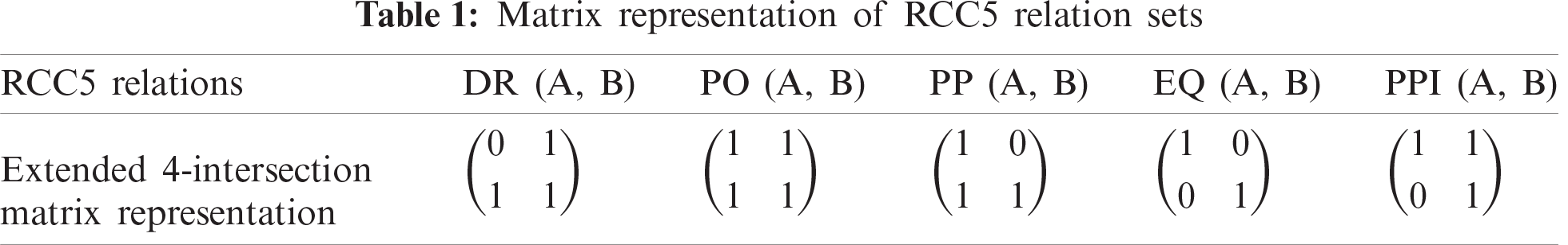
We represent the set as
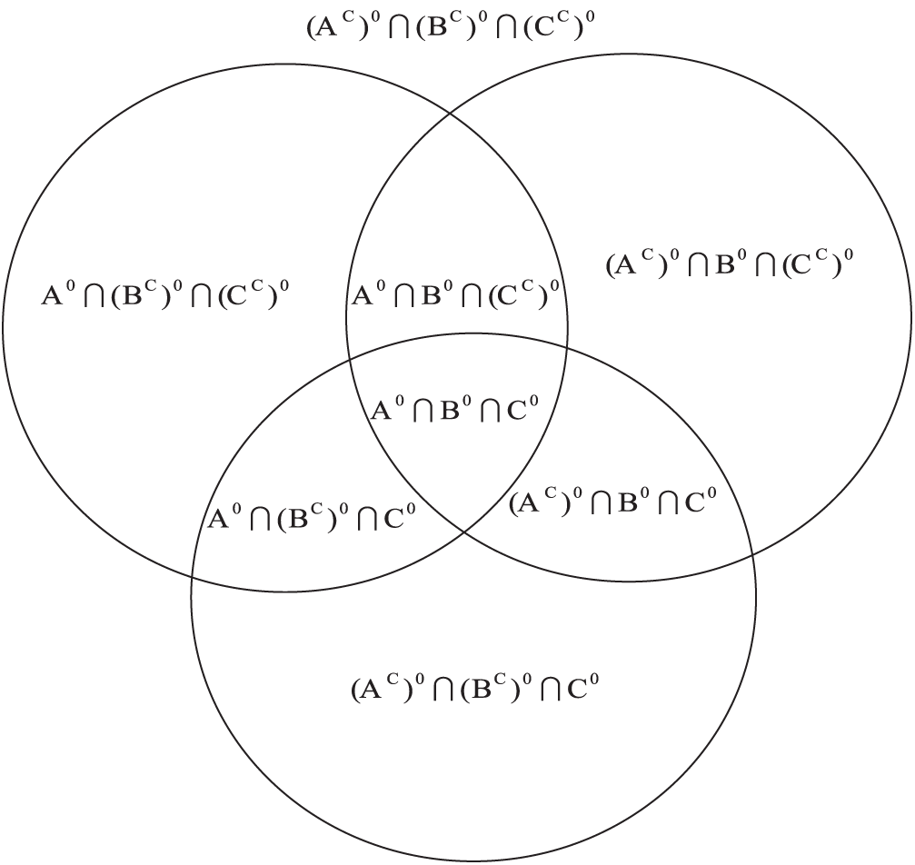
Figure 1: Topology relation of three simple regions
The matrix corresponding to the eight regions divided by space can be expressed as
In 2010, He Yunbin et al. [18] divided the space into eight regions based on the eight-direction cone model. Each direction is divided into two sub-directions. For example, the N direction is composed of the EN direction and the WN direction. In the same way, the other directions can be obtained:
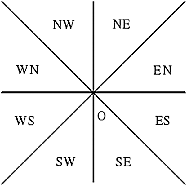
Figure 2: Direction cone model
In 2020, Li et al. [19] proposed a three-dimensional topology-azimuth compound relationship model R5DOS model based on RCC-5 theory and an eight-direction cone model. This model fills the research deficiencies in the field of compound relational models in three-dimensional space. Compared with the existing three-dimensional space MBR model, the R5DOS model has higher accuracy and more complete expression.
Based on the hexagram limit and the eight-direction cone model, the R5DOS model divides the space into 16 regions:
According to the model description, the region in which the center of the simple region exists is called the “strong existence region.” When the model only considers this “strong existence region,” then we can obtain the following:
Considering the topological relationship at the same time, for the three simple regions A, B, and C in the three-dimensional space, the model is
Here,
According to the topological relationship of B and C, the reference object, and the existence region, we have two cases:
1: When the centers of reference objects B and C appear in different areas:
2: When there is only one sphere center of the reference objects B and C or they appear in the same area.
According to these conditions, we can obtain
3.2 Abstract Expression of the UAV Model
Formation control of UAVs is an especially important research field. In recent years, due to the maturity of mEMSs (micro-electro-mechanical systems) and micro-sensor technology, [20–22] miniaturized and clustered UAV formation research has been increasingly studied. Small UAVs are characterized by low cost and greater flexibility. At present, various countries are actively studying the formation control technology of UAVs.
The basic idea of the leader-follower method is to divide the UAV into leader aircraft and follower aircraft. The leader unit can be one or more UAV, and then the other units are followers. Of course, leaders and followers can be interchangeable and followers can share the status and information of the leader. This method can reduce the complexity of the system: the operation is simple, and the control is sensitive. Therefore, it is suitable for complex environments.
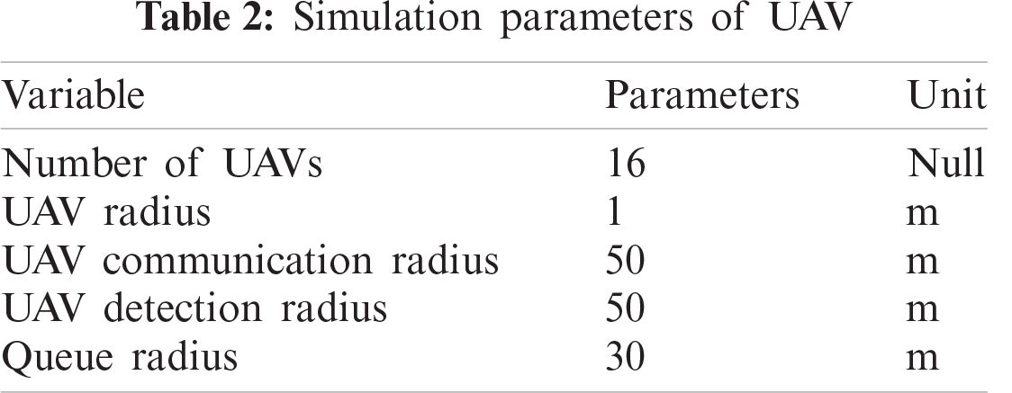
According to the R5DOS model, we can divide the UAV formation into a queue area and communication area. We assume that the detection range and communication range of the UAV are consistent. The parameters of the UAV are set as presented in Tab. 2.
We define the UAV formation according to the R5DOS-intersection model, as described below.
Definition 1: The area C is inside the area B, and the area C is called the hole of the area B, which satisfies PP(B, C). According to the R5DOS-intersection model, we can get Fig. 3.
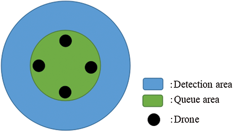
Figure 3: Formation and communication zones
R5 layer = (1 0 1 1)
Definition 2: for the R5 layer, we define in Tab. 3 an operator “∨” about the set {0, 1}.
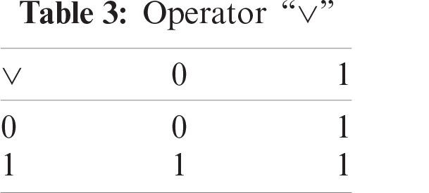
According to Tab. 3, we can learn the following.
Proposition 1:
Then we can obtain five topological cases corresponding to the R5 layer:
Theorem 1:
For any target point A and UAV formation B, their topological relationship must be one of the R5 relationships. Then, according to proposition 1, there is
Similarly, the topological relationships between pairs of A, B, and C must also belong to the set of R5 relations:
Theorem 2:
The topological-directional relationship between the three simple regions given by the R5DOS-intersection model is exclusive and complete; that is, the A, B, and C pairwise relationships belong to the R5 relation set.
4 UAV Formation Model Establishment
We divide the UAV formation area into a queue area and communication area. The queue area is the area where the UAV maintains its formation, and the communication area is the area where the UAVs detect during operation. When obstacles appear in the communication area, timely obstacle avoidance can ensure the integrity and safety of the UAV.
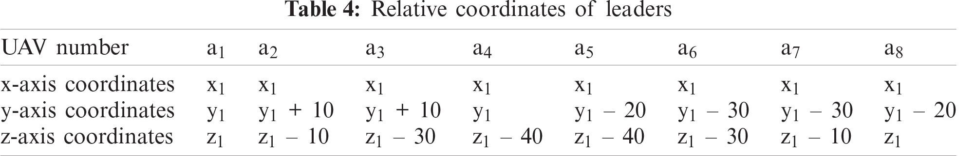
We use the leader-follower method to control the UAV formation. To increase the robustness of the formation, and to reduce the communication burden of the leader aircraft, we set eight UAV as leaders, and eight as followers. There is a one-to-one correspondence between leaders and followers. The leaders and followers can be interchanged at any time. Thanks to the current development of small UAV technology, UAVs have more powerful performance than before; thus, our model will not increase the cost. We have 16 planes to construct 16 spatial regions. The UAVs on the positive x-axis are the leaders numbered
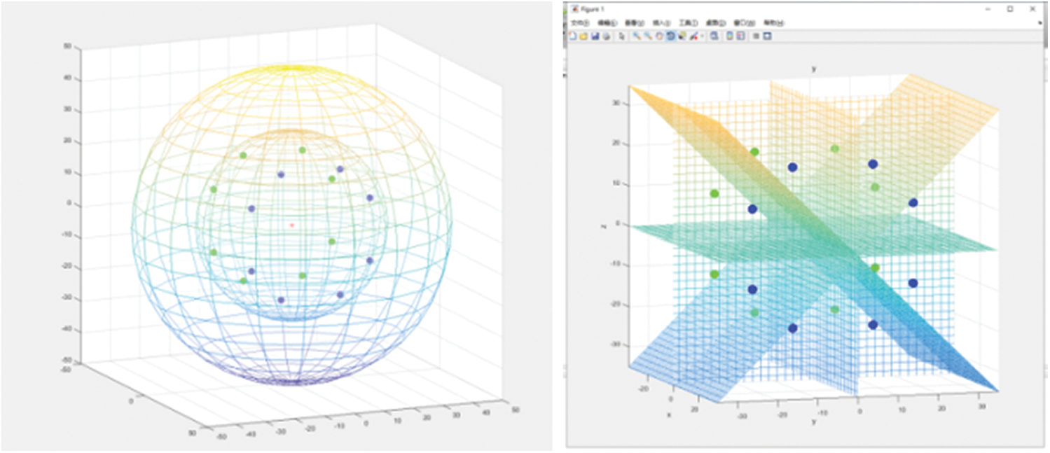
Figure 4: Abstract expression of UAV formation
According to the simulation parameters, the coordinates of our a1 UAV is
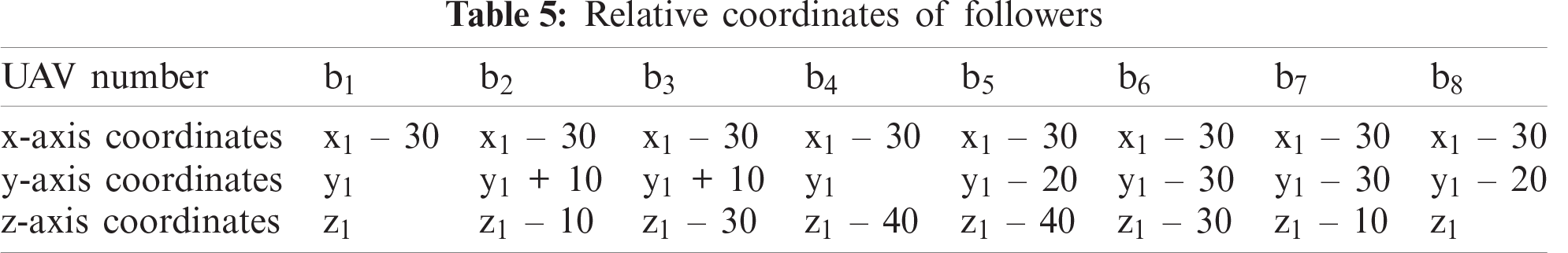
We improve the R5DOS model so that the DOS layer records the number of UAVs in each area and the information about obstacles in the current area. Thus, there are
Then, the initial formation model of UAV can be described as follows:
The UAV formation algorithm in this paper is based on a distributed transmission mechanism. Excellent UAV formation algorithms generally have the advantages of high efficiency, low cost, and high robustness. The centralized mode of transmission integrates and processes the information after all the information is passed to a specified node. The communication burden is very large due to the transmission to the UAV where the node is located. This centralized mode of transmission becomes less efficient as the number of UAVs increases. Moreover, once the leader fails, the entire UAV formation may collapse. While the distributed transmission mechanism can avoid this, it has low efficiency. To solve this problem, we combine the distributed and centralized transmission modes.
The distributed transmission mechanism works when each node sends its own information to the adjacent node, and each node receives the information of the adjacent node. After the information of each UAV is integrated, the current overall information will be sent to the followers of the leader. We set the transmission mechanism between the follower and the leader to be centralization, and the transmission mechanism between the leaders is set to be distribution. The communication topology of the UAV formation is shown in Fig. 5.
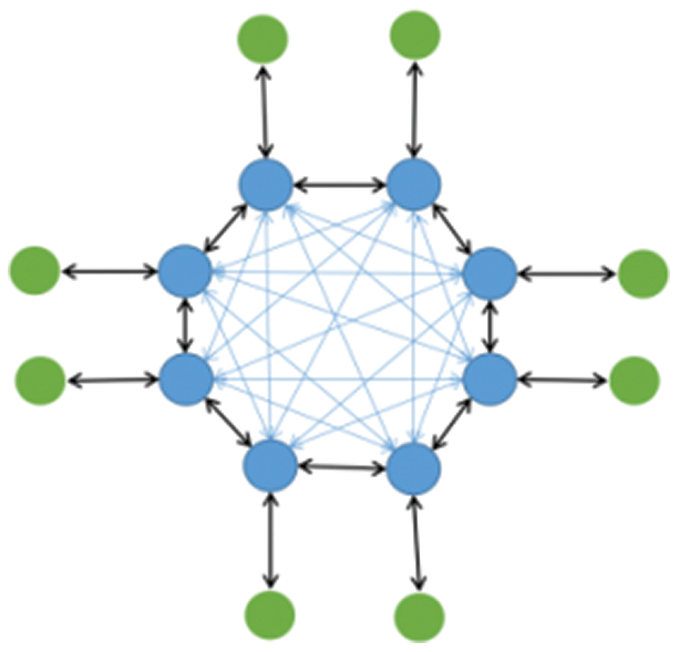
Figure 5: Communication topology of distributed UAV formation
The blue points are leaders and the green points are followers.
As shown in the Fig. 5, the annular formation makes each node in the formation adjacent to each other, and thus it takes only three iterations to obtain the complete formation information for each UAV.
First step: each follower sends its own information to its corresponding leader.
Second step: each leader broadcasts its own information. Because of the ring structure of the formation, only one iteration is required. All of the leaders can obtain the complete formation information, and there is no information redundancy.
Third step: each leader sends the complete information of the formation to its follower.
Most studies in recent years have not considered the impact of UAV formation on the communication between UAVs. In 2017, Ma et al. [23] adopted a rectangular formation structure with one-way communication of six UAVs. For better comparison, we extended these six UAVs to eight UAVs. In 2018, Park et al. [24] proposed an infrastructure-based UAV formation model (referred to as a grid formation) that can maximize the range of UAV operations and improve the throughput of the UAV network. However, their model does not consider the information transmission between UAVs while ensuring the maximum range of UAV operations. This results in the UAV being unable to obtain the information of the whole formation in a short time. Different communication topologies are presented in Fig. 6.
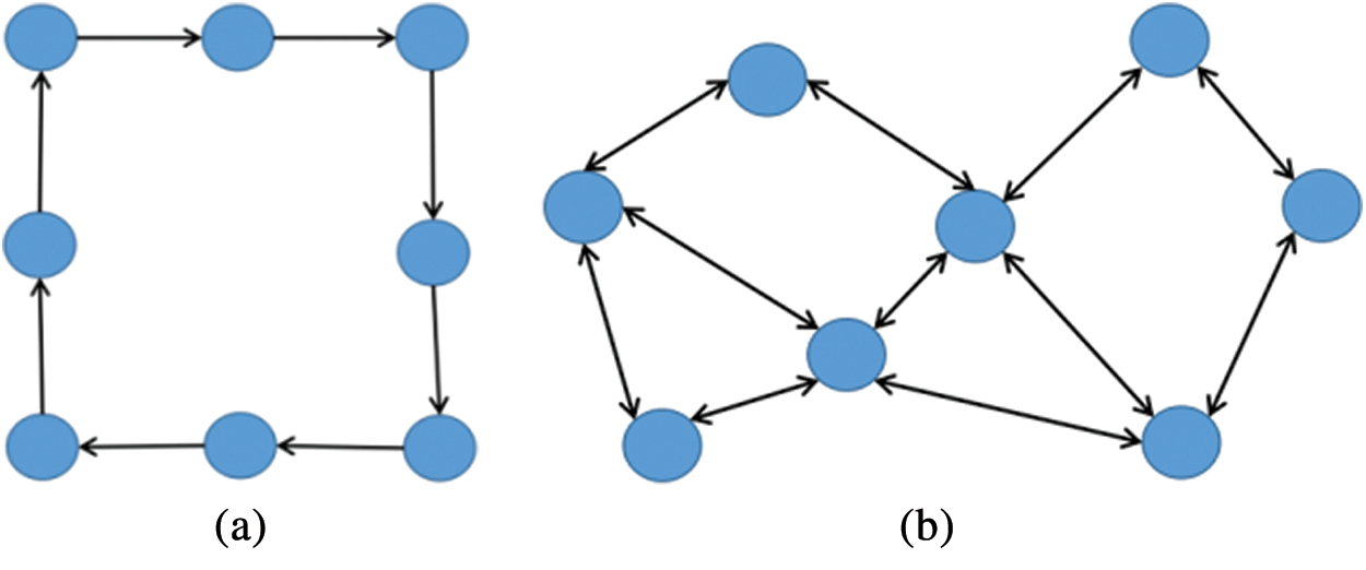
Figure 6: (a) Rectangular communication topology (b) Grid formation communication topology
We can compare the rectangular formation and grid formation communication topology model with the formation based on the R5DOS model. The transmission mechanism of rectangular one-way communication requires n-1 iterations for each UAV to obtain the information of the whole formation; this is based on the number of UAVs. Thus, eight UAVs need to iterate seven times, and the information redundancy generated by each iteration is very large. The grid formation requires three iterations.
To better explore the proposed models, we define three indices. These indices are also used to determine the cost of finishing a complete communication transmission and the time consumed. Note that we only calculate the cost of the leader and assume that the UAV does not produce data loss in the effective range of communication.
Communication cost: The communication cost we define in this article refers to the total amount of communication required by the UAV formation for a complete communication process. We assume that the amount of information carried by each UAV is i, and the cost of receiving and sending information is I. For the cases where various amounts of information are received and sent, we take the maximum value. In each iteration, the total amount of information generated is n, and there is a total of j iterations. Then the total communication cost is as follows.
According to the UAV formation model, we can obtain Tab. 6.
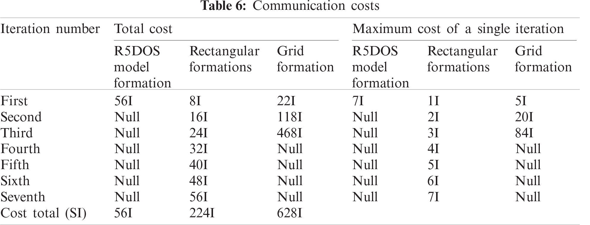
We can see that the total cost of the rectangular formation is 224 I, while the total cost of the grid formation is 628 I. Moreover, two formations will produce a great deal of information redundancy in the exchange of information, and the total cost of the R5DOS model is 56 I, which is reduced by 75% and 91.08%, respectively, compared with these two models. In each iteration, the leader of the grid formation needs to bear a cost of up to 84 I; meanwhile, in the rectangular formation, the leader only needs to bear a cost of 7 I, which is a 91.67% decrease. As we can clearly see, the R5DOS model can effectively reduce the communication cost and the communication burden of the leader aircraft. Because the information redundancy generated by the rectangular formation and grid formation is relatively large, we remove their information redundancy.
After removing information redundancy, we can obtain the following communication cost as shown in Tab. 7.
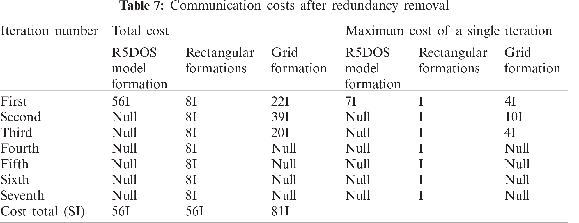
After redundancy removal, we find that the communication costs of rectangular formation and grid formation decrease significantly. However, for the grid formation, because the number of communication channels of a single UAV is inconsistent, there will always be data redundancy. With the R5DOS, the total cost of model formation is 30.86% lower than that of the grid formation.
Time cost: We define time cost as: the time it takes for the UAV to complete an information transmission and calculation. We assume that the transmission speed of information in the transmission process is
Because the relative distance between UAVs is constant when the formation is flying, we can calculate the time cost of the UAV formation.
The R5DOS model formation time cost is as follows:
To determine the rectangular formation time cost, we assume that the rectangular formation is the tangent rectangle of the UAV detection area, and therefore the distance between the UAV is
For the grid formation time cost, because the formation needs to maintain the largest detection area. Then under the premise of ensuring the most ideal effect, we assume that the distance between UAVs is 50m, then the following formula can be obtained.
According to the calculation, the time cost of the R5DOS model is reduced by 73.66% compared with the rectangular formation. Compared with the grid type formation, the transmission cost is reduced by 70.2%, and the calculation cost is reduced by 61.11%, and the R5DOS model does not need to eliminate the cost of information redundancy. (3) Energy cost: In this paper, we define the energy cost as the energy consumed by a single UAV for detection operations in a fixed period of time. We assume that the energy required for the UAV to fully detect the surrounding environment is
Rectangular formation can be detected by referring to the R5DOS model formation. The consumption of each UAV is
Grid formation ensures that each UAV has the largest detection area and causes each UAV to spend energy
In summary, the distributed UAV formation model based on the R5DOS model can effectively reduce the cost of communication, calculation, and energy cost of the UAV formation. The model can also extend the operation time of the formation and optimize the communication pressure on the leader aircraft. Moreover, it can enhance the endurance and robustness of UAV formations.
6 Simulation Experiment on Robustness of UAV Formation
Simulation results of UAV formation motion based on the R5DOS model are shown in Figs. 7 and 8.
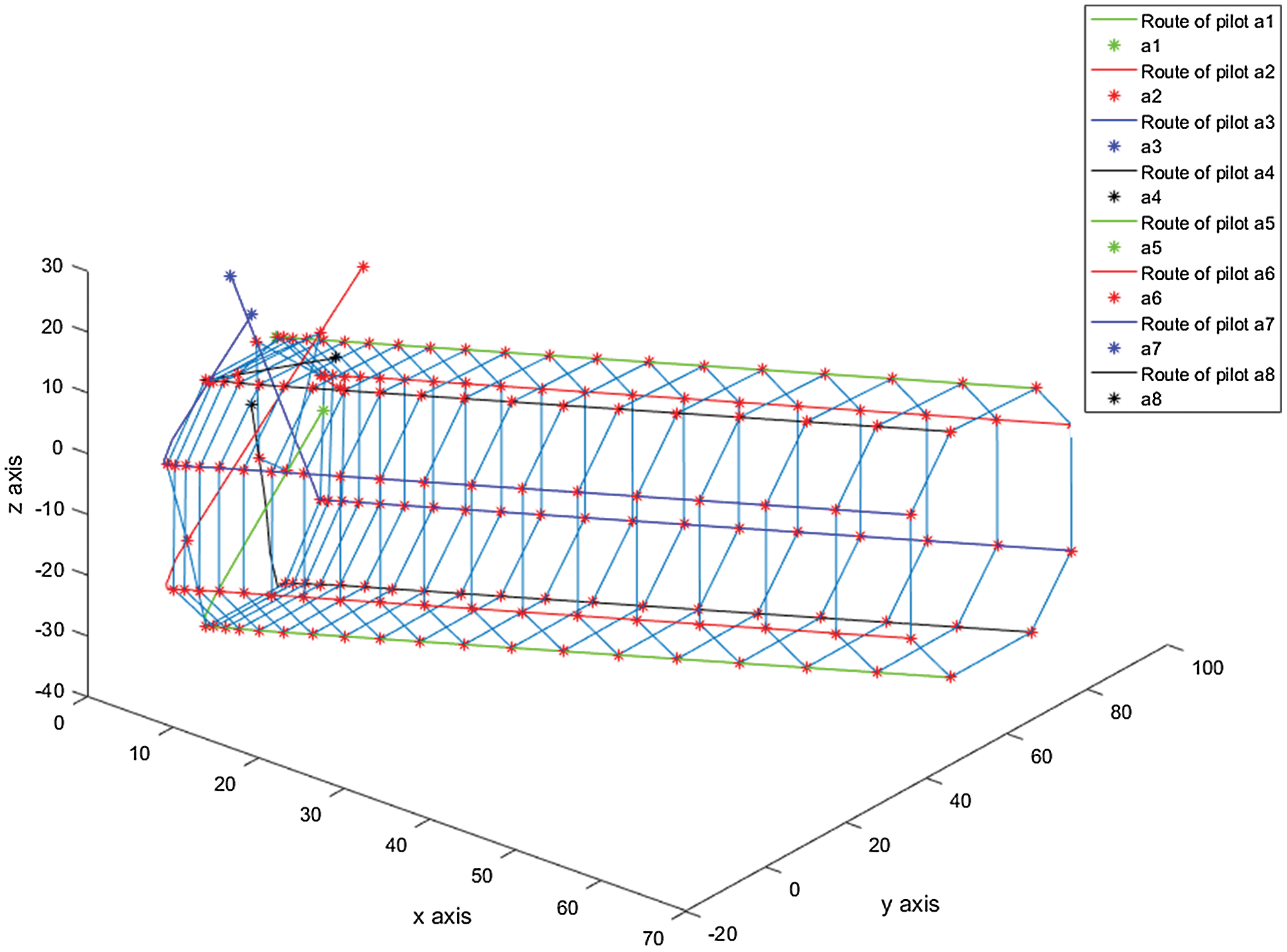
Figure 7: The trajectory of the leader formation
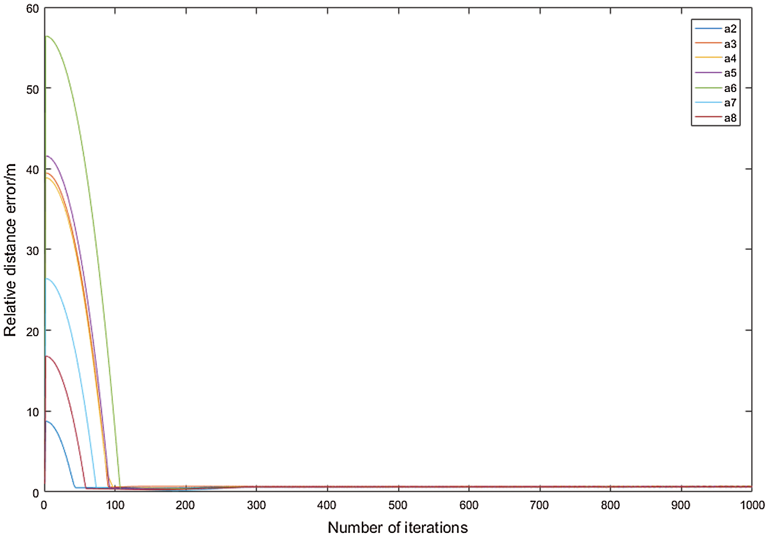
Figure 8: Relative distance error change
We adopt distance-based adaptive acceleration to enable the UAV to reach its formation position in a short time by iteration. To facilitate observation, we only plot the formation of the leader aircraft. It is clear from Fig. 7 that the desired formation can be entered and maintained. Fig. 8 describes the distance between the individual UAVs and the desired formation. The simulation results show that the multiple UAVs can enter and maintain the desired formation.
To simulate unexpected situations during formation flight, we randomly let n leaders lose their operational ability during iteration to test the robustness of the formation. The algorithm pseudo code is as follows:
1:DOS ← DOS layer data
2: Scan DOS each time the UAV transmits information
3: if DOS == 0/ If the matrix element of the leader is 0, the leader is damaged
4: a = find (min a nce)/find the follower nearest the damaged leader
5: follow (t) = follow (t – 1) + 0.03 * (leader (t – 1) – follow (t – 1));// to plan the path for the follower
6: if distance <= k // setting threshold
7: follow (direction, v) = leader (direction, v)/when the original trajectory of the follower and the leader is less than the predetermined threshold, maintain formation
8: end if
9: end if
10: end for
11: return
According to this algorithm, we can simulate the leader after damage (see Figs. 9–11).
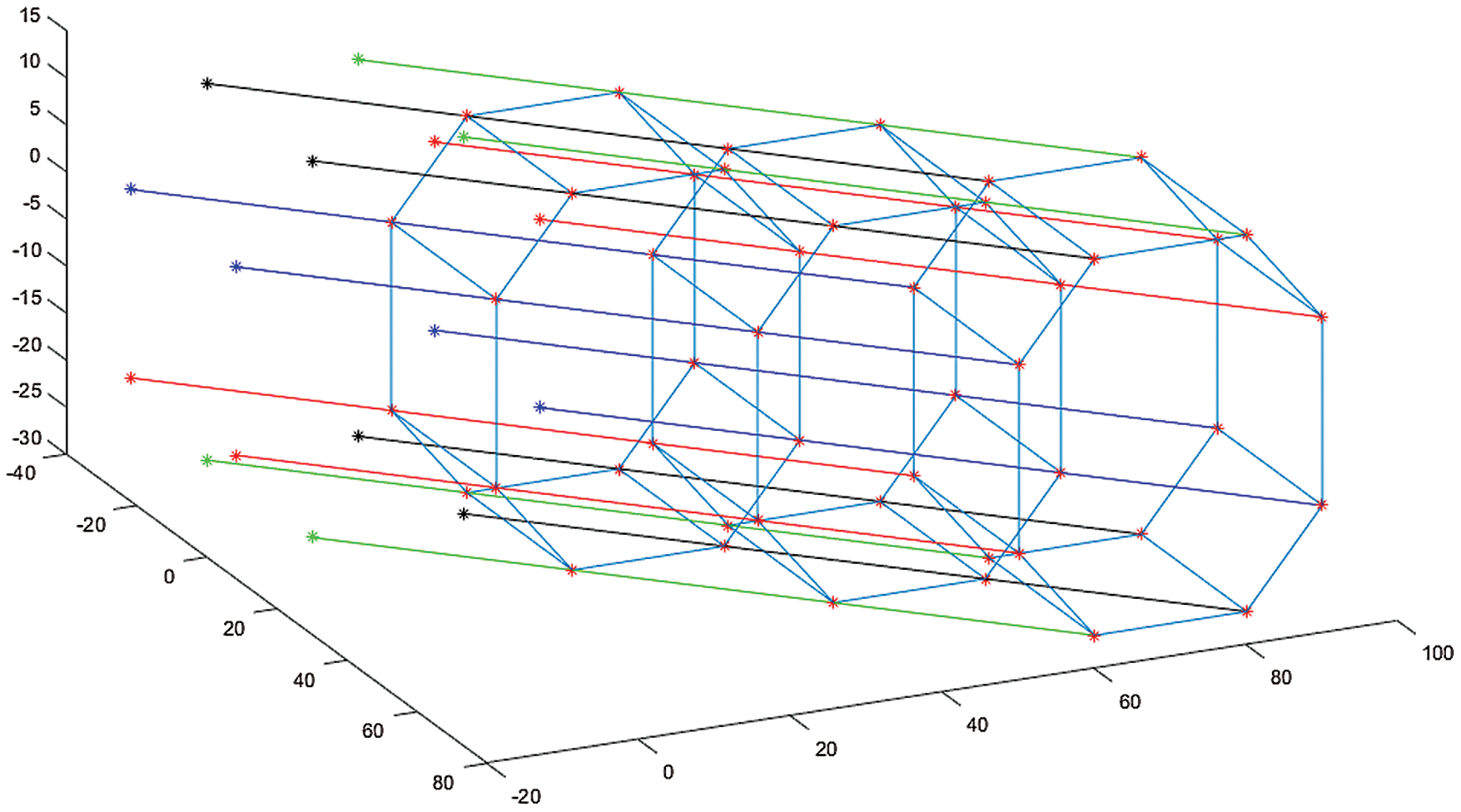
Figure 9: Trajectory of UAV formation
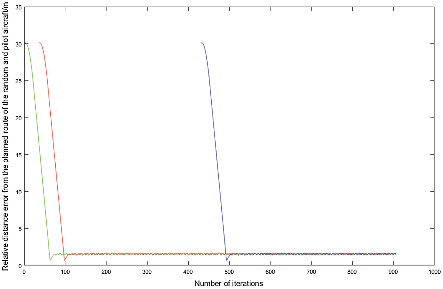
Figure 10: Distance error change of the follower
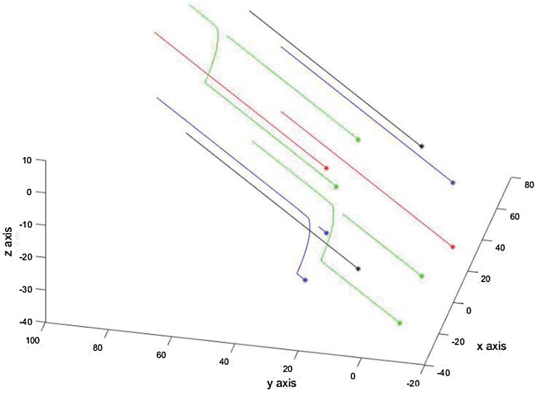
Figure 11: Measures taken by the formation after the failure of the leader
Fig. 9 shows the complete UAV formation trajectory, and Fig. 10 shows the relative distance error change of the nearest follower after the leader fault.
For convenience of observation, we ploy the path between the leader and the follower. It can be seen from Fig. 11 that after the leader is damaged, the nearest follower can react quickly. In a short time, the UAV formation based on the R5DOS model can replace eight leaders, which demonstrates significantly increased formation robustness and stability.
Based on the R5DOS model, 16 UAV are placed in 16 space regions and enter a formation. The flight cost and robustness of the formation are studied. Compared to the R5DOS rectangular formation and grid formation, our model’s formation can effectively reduce the communication time and energy cost during UAV formation flight. The UAV team can enter formation and maintain stability, ensure integrity of communication, and demonstrate enhanced formation robustness.
Acknowledgement: We thank LetPub (https://www.letpub.com) for its linguistic assistance during the preparation of this manuscript.
Data Availability: This paper has code as the basis of the paper, and the results are obtained based on the calculation results of the code.
Funding Statement: This study was supported by the National Natural Science Foundation of China (Grant Nos. 41601454 and 41671397; URL: http://www.nsfc.gov.cn/), Science and Technology Development Project of Jilin Province, China (Grant No. 20191001008XH; URL: http://www.jlkjxm.com/), Science Foundation of Jilin Provincial Education Department, China (Grant No.: JJKH20200329KJ; URL: http://jyt.jl.gov.cn/), Development and Reform Commission Project of Jilin Province, China (Grant No. 2020C037-7; URL: http://jldrc.jl.gov.cn/), and Ecology and Environment Department Project of Jilin Province, China (Grant Nos. 2019-02 and 2020-18; URL: http://sthjt.jl.gov.cn/).
Conflicts of Interest: The authors declare that they have no conflicts of interest to report regarding the present study.
1. N. Lin and J. Tang, “A novel improved bat algorithm in uav path planning,” Computers, Materials & Continua, vol. 61, no. 1, pp. 323–344, 2019. [Google Scholar]
2. Y. Liu and X. Yan, “Sliding-mode PID control of UAV based on particle swarm parameter tuning,” Computers, Materials & Continua, vol. 63, no. 1, pp. 469–487, 2020. [Google Scholar]
3. A. Qayyu, I. Ahmad and M. Iftikhar, “Object detection and fuzzy-based classification using UAV data,” Intelligent Automation & Soft Computing, vol. 26, no. 4, pp. 693–702, 2020. [Google Scholar]
4. L. Juang and S. Zhang, “Intelligent service robot vision control using embedded system,” Intelligent Automation & Soft Computing, vol. 25, no. 3, pp. 451–458, 2019. [Google Scholar]
5. Z. Sun, Y. Tian and J. Wang, “A novel projected fletcher-reeves conjugate gradient approach for finite-time optimal robust controller of linear constraints optimization problem: Application to bipedal walking robots,” Optimal Control Applications and Methods, vol. 39, no. 1, pp. 130–159, 2018. [Google Scholar]
6. L. Zhang, L. Bai and X. Zhang, “Cultivated land monitoring system based on dynamic wake-up uav and wireless of distributed storage,” Computers, Materials & Continua, vol. 61, no. 2, pp. 817–828, 2019. [Google Scholar]
7. B. H. Y. Alsalam, K. Morton and D. Campbell, “Autonomous UAV with vision based on-board decision making for remote sensing and precision agriculture,” in 2017 IEEE Aerospace Conf., Big Sky, MT, pp. 1–12, 2017. [Google Scholar]
8. T. Ahn, J. Seok and I. Lee, “Reliable flying IoT metworks for UAV disaster rescue operations,” Mobile Information Systems, vol. 2018, pp. 1–12, 2018. [Google Scholar]
9. E. Dujoncquoy, “UAV-based 3d outcrop analog models for oil and gas exploration and production,” in IGARSS, 2019–2019 IEEE Int. Geoscience and Remote Sensing Sym., Yokohama, Japan, pp. 6791–6794, 2019. [Google Scholar]
10. X. H. Wu, Q. F. Guo and J. Zhang, “Application of double GPS multi-rotor UAV in the investigation of high slope perilous rock-mass in an open pit iron mine,” Geotechnical and Geological Engineering, vol. 38, pp. 71–78, 2020. [Google Scholar]
11. V. Roberge and M. Tarbouchi, “Fast genetic algorithm path planner for fixed-wing military UAV using GPU,” IEEE Transactions on Aerospace and Electronic Systems, vol. 54, no. 5, pp. 2105–2117, 2018. [Google Scholar]
12. S. J. Levulis, P. R. DeLucia and S. Y. Kim, “Effects of touch voice and multimodal input and task load on multiple-UAV monitoring performance during simulated manned-unmanned teaming in a military helicopter,” Journal of the Human Factors and Ergonomics Society, vol. 60, pp. 1117–1129, 2018. [Google Scholar]
13. J. Zhang and J. Yan, “Fixed-wing UAV formation control design with collision avoidance based on an improved artificial potential field,” IEEE Access, vol. 6, pp. 78342–78351, 2018. [Google Scholar]
14. K. Chang and Y. Xia, “UAV formation control design with obstacle avoidance in dynamic three-dimensional environment,” SpringerPlus, vol. 5, no. 1, pp. 1–16, 2016. [Google Scholar]
15. D. A. Randell and A. G. Cohn, “Modelling topological and metrical properties in physical processes,” in Proc. of First Int. Conf. on Principles of Knowledge Representation and Reasoning, Toronto, vol. 89, pp. 357–368, 1989. [Google Scholar]
16. D. A. Randell, Z. Cui and A. G. Cohn, “A spatial logic based on regions and connection,” in Proc. of Third Int. Conf. on Principles of Knowledge Representation and Reasoning, Cambridge, MA, USA, pp. 165–176, 1992. [Google Scholar]
17. M. Egenhofer and R. D. Franzosa, “Point-set topological spatial relation,” International Journal of Geographical Information System, vol. 5, no. 2, pp. 53–174, 1991. [Google Scholar]
18. Y. B. He and J. Bian, “Research on the model of spatial direction relation in spatial reasoning,” Computer & Digital Engineering, vol. 38, no. 4, pp. 62–65, 2010. [Google Scholar]
19. J. Li, W. Zhang, Y. Hu and Z. Wang, “Representation and reasoning of three-Dimensional spatial relationships based on R5DOS-Intersection model representation and reasoning based on R5DOS model,” Complexity, vol. 2020, pp. 1–15, 2020. [Google Scholar]
20. B. Cao, W. Dong, Z. Lv, Y. Gu, S. Singh et al., “Hybrid microgrid many-objective sizing optimization with fuzzy decision,” IEEE Transactions on Fuzzy Systems, vol. 28, no. 11, pp. 2702–2710, 2020. [Google Scholar]
21. B. Cao, J. Zhao, Y. Gu, Y. B. Ling and X. Ma, “Applying graph-based differential grouping for multiobjective large-scale optimization,” Swarm and Evolutionary Computation, vol. 53, 2020. https://doi.org/10.1016/j.swevo.2019.100626. [Google Scholar]
22. B. Cao, S. Fan and J. Zhao, “Quantum-enhanced multiobjective large-scale optimization via parallelism,” Swarm and Evolutionary Computation, vol. 57, 2020. https://doi.org/10.1016/j.swevo.2020.100697. [Google Scholar]
23. P. Ma, M. Le and J. Ji, “Control of multi-UAV cooperative formation with equality communication time-delay,” Acta Aeronautica et Astronautica Sinica, vol. 38, no. 1, pp. 157–162, 2017. [Google Scholar]
24. S. Park, K. Kim, H. Kim and H. Kim, “Formation control algorithm of multi-UAV-based network infrastructure,” Applied Sciences, vol. 8, no. 10, pp. 1740, 2018. [Google Scholar]
 | This work is licensed under a Creative Commons Attribution 4.0 International License, which permits unrestricted use, distribution, and reproduction in any medium, provided the original work is properly cited. |