DOI:10.32604/cmc.2021.018793
| Computers, Materials & Continua DOI:10.32604/cmc.2021.018793 | |
| Article |
Design and Implementation of T-Shaped Planar Antenna for MIMO Applications
1Department of ECE, SNS College of Technology, Coimbatore, 641035, Tamil Nadu, India
2Department of EEE, SNS College of Technology, Coimbatore, 641035, Tamil Nadu, India
*Corresponding Author: T. Prabhu. Email: prabhutcbe1206@gmail.com
Received: 21 March 2021; Accepted: 26 April 2021
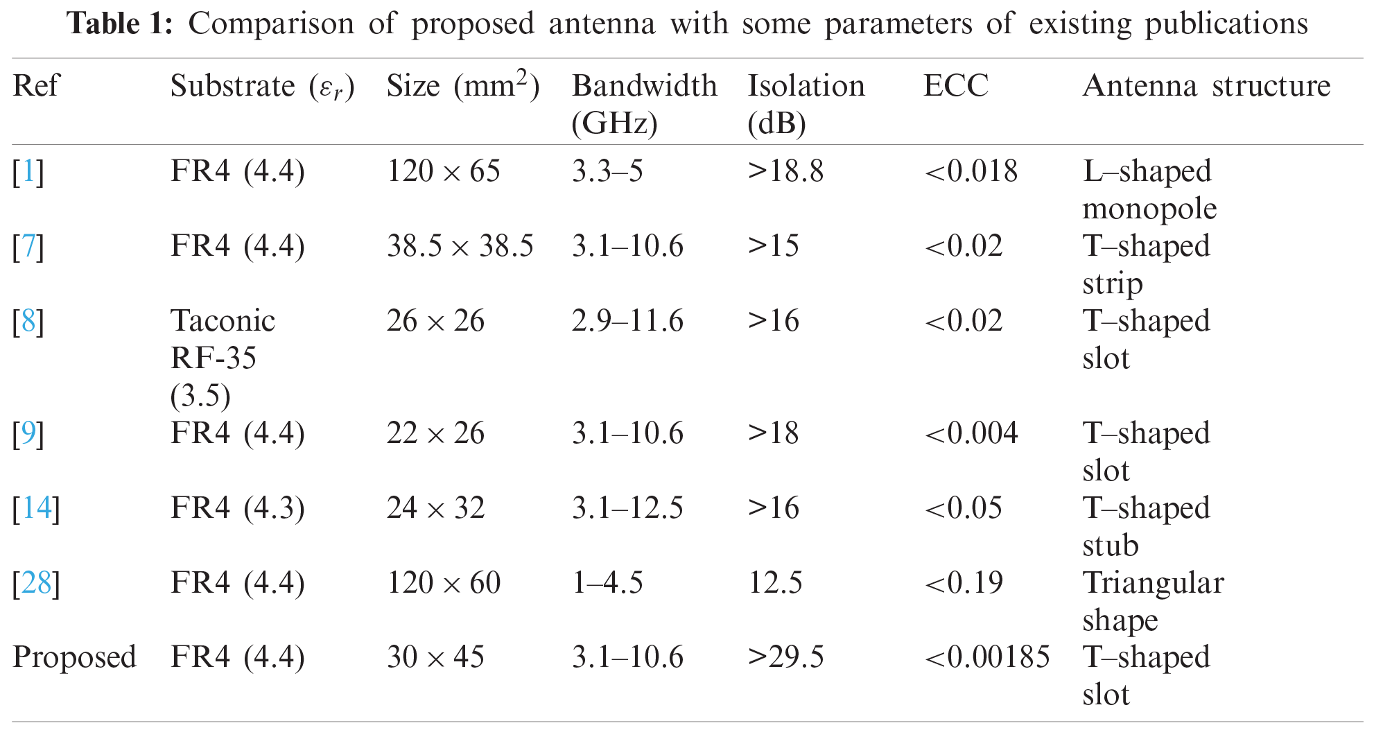
Abstract: This paper proposes, demonstrates, and describes a basic T-shaped Multi-Input and Multi-Output (MIMO) antenna with a resonant frequency of 3.1 to 10.6 GHz. Compared with the U-shaped antenna, the mutual coupling is minimized by using a T-shaped patch antenna. The T-shaped patch antenna shapes filter properties are tested to achieve separation over the 3.1 to 10.6 GHz frequency range. The parametric analysis, including width, duration, and spacing, is designed in the MIMO applications for good isolation. On the FR4 substratum, the configuration of MIMO is simulated. The appropriate dielectric material ɛr = 4.4 is introduced using this contribution and application array feature of the MIMO systems. In this paper, FR4 is used due to its high dielectric strength and low cost. For 3.1 to 10.6 GHz and 3SRR, T-shaped patch antennas are used in the field to increase bandwidth. The suggested T-shaped MIMO antenna is calculated according to the HFSS 13.0 program simulation performances. The antenna suggested is, therefore, a successful WLAN candidate.
Keywords: Multi-input and multi-output; FR4 substratum; t-shaped patch antennas; ISM band; HFSS 13.0; WLAN
Multiple Input and Multiple Output (MIMO) devices can send and receive simultaneous signaling at the same power level and maximize high data rate demands in modern communication systems. This is because the MIMO mechanism will increase the channel’s capability at both sides without increasing transmitting power. MIMO devices have considerable interest in improving stability and power on the platform of wireless mobile communications.
In compact MIMO antenna architecture, one crucial consideration is to minimize associations between certain elements, particularly the interconnections between various elements and the electromagnetic interactions [1]. When the radio contact includes more than one antenna, this is known as (MIMO) [2]. MIMO can be used for both channel robustness and channel efficiency enhancements.
To ultimately gain from MIMO [3], it is essential to use channel coding for distinguishing information from various channels. Several types of MIMO can be used from SISO, like SIMO and MISO, to complete the MIMO system. This requires processing but gives additional channel robs/data throughput capacity. These all can increase efficiency significantly, but usually at the disadvantage of the extra processing and the number of antennas used [4]. When selecting the correct alternative, performance balances against costs, available capacity, and the resulting battery life have to be accomplished. Shannon’s law determines the highest rate at which erroneous data may be transported in the presence of noise over a given bandwidth.
Although some changes can be made to simplify the modulation system and increase the signal-to-noise ratio, these changes are not necessarily straightforward or inexpensive, and they often represent a compromise to accommodate the different factors involved. Therefore, more ways to enhance the data output on various networks are required [5]. MIMO is one way to improve wireless networking and is thus of great importance. The fact that MIMO can provide additional storage capacity is one of the main benefits of spatial multiplexing. This is achieved by spatial multiplexing by using multiple paths as external channels for data transfer. The overall volume of data accessible on radio channels is constrained by the physical limitations established by Shannon’s law.
This section explores the related research on the design and analysis of Ulta-WideBand (UWB) for wireless applications. A new design [6] for a wideband dual-polarized aperture-coupled patch antenna with dumbbell-shaped coupling slots is presented. The printed antenna consists of two stacked patches and an aperture slotted ground plane, excited using a microstrip line feed. A two-slot dual-polarized antenna with a return loss bandwidth of 505 MHz is introduced using the proposed configuration. The proposed antenna is designed for 2.45 GHz and achieves stable and desirable radiation characteristics across the band. There the antenna proposed is composed of two UWB-performing microstrip-fed offset antenna components [7]. The antenna elements are positioned perpendicular to each other to achieve high insulation and polarization diversity. A parasite T-shaped strip is used as a decoupling mechanism between the radiating components to eliminate the reciprocal relation further. Furthermore, the 5.5 GHz notched band is made by grafting onto the ground a pair of L-slides. The prototype of the antenna has been designed and tracked with a small scale of
Ultra-wideband is a wireless technology that requires deficient energy levels for fast, high-frequency communications across most radio spectrums. UWB has conventional non-cooperative visualization capabilities. UWB typically applies to an indicator or device with a limited relative bandwidth exceeding 20% or an absolute range exceeding 500 MHz. As the applications of UWB MIMO antenna supports for long range communication with low transmission power this band can be utilized, that in-turn applicable for Internet of Things (IoT). A study and order of 14th February 2002 utilizing the Federal Communications Commission authorize unlicensed utilization of the UWB at 3.1–10.6 GHz. This is projected to offer a competent utilization of scarce radio bandwidth whereas enabling both the high rate of Personal Area Network (PAN) wireless connectivity data and long-range applications of low data rate in addition to imaging and radar systems.
The general concept of a single-link contact device is seen in Fig. 1. It consists of three main contact components: a transmitter, channel, and receiver. The transmitter input information is the message to be transmitted to the destination from the source. The transmitter’s essential function is to relay the message to the channel via an antenna. An antenna is a way to radiate (send antenna) or receive (absorb antenna) radio waves. Data modulation is the systematic modification of the carrier signal’s characteristics as amplitude, phase, or frequency by message signal. (a) ease of transmission, (b) minimize noise and interference, and (c) relay multiple signals over a single channel can be used to modulate a message using a sender. It is amplified through a power amplifier before transmitting the signal out of the transmission antenna. The channel is the mechanism used to meet the destination or source of the transmitting data. When the data is transmitted through the channel, other undesirable results are seen. For example, it absorbs the noise from the local environment, and since the signal reflects and responds from different barriers to the signal line, the signal sent by the transmitter is emitted in various forms, also known as multi-track, at various times. Even the transmitter signal may be entirely obscured or blacked out by barriers. The recipient’s job is to remove the requested message from the received signal.
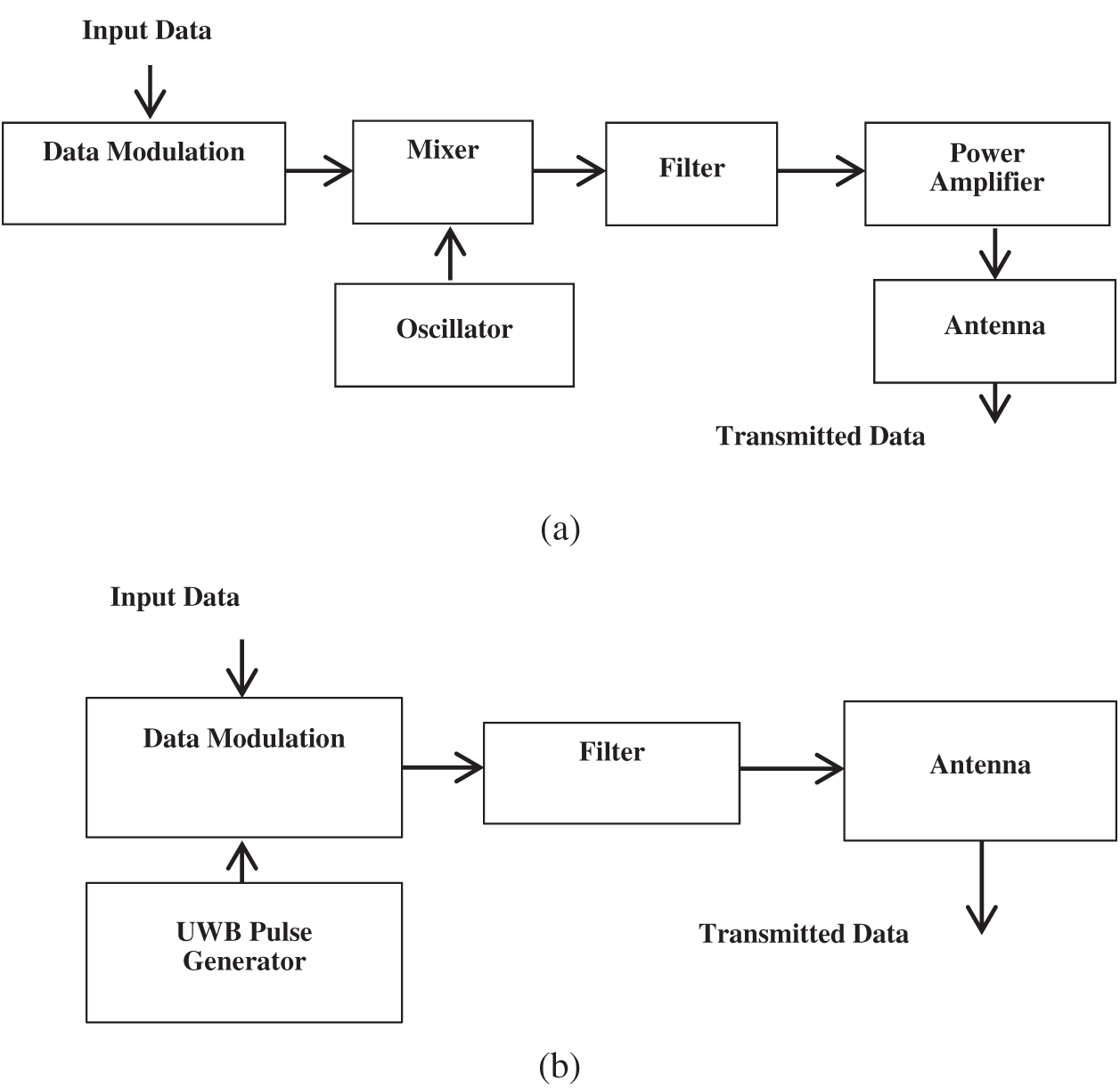
Figure 1: Typical block diagram (a) Narrowband (b) UWB transmitter
UWB communication differs radically from all other communication methods because the pulses produced by a UWB pulse generator are used to communicate between transmitters and recipients by extremely narrow RF pulses. The use of a short-term pulse as the contact blocks directly produces an extensive bandwidth, as the interpretation of the Fourier frequency domain is based on the assumption that a minimal signal in a time domain provides a comprehensive spectrum signal. An important distinction between standard radio transmissions and UWB radio transmissions is the standard transmissions relay information by separate energy/frequency/phase modulation of the sinusoidal wave. UWB transmissions can relay data by producing radio power at particular times and taking up broad bandwidths, allowing pulse or time modulation. Details on UWB signals may also be transmitted (modulated) by encoding pulse polarity and pulse amplitude/orthogonal pulses. UWB pulses can be emitted sporadically to support time-position modulation at comparatively lower pulse frequencies and be emitted at rates up to the opposite of the UWB pulse spectrum. At channels pulse rates above 1.3 Gps, pulse-UWB systems assisted forward error correction encoded data rates above 675 Mbps were demonstrated. UWB communication is carriers accessible, such that data, as in the case of narrowband and broadband systems, are not modulated in a continuous waveform with a particular carrier frequency.
This section discusses the Two T-shaped planar antennae for the operation of the MIMO design technique in detail. In Fig. 2, the planned flexible textile antenna is shown.
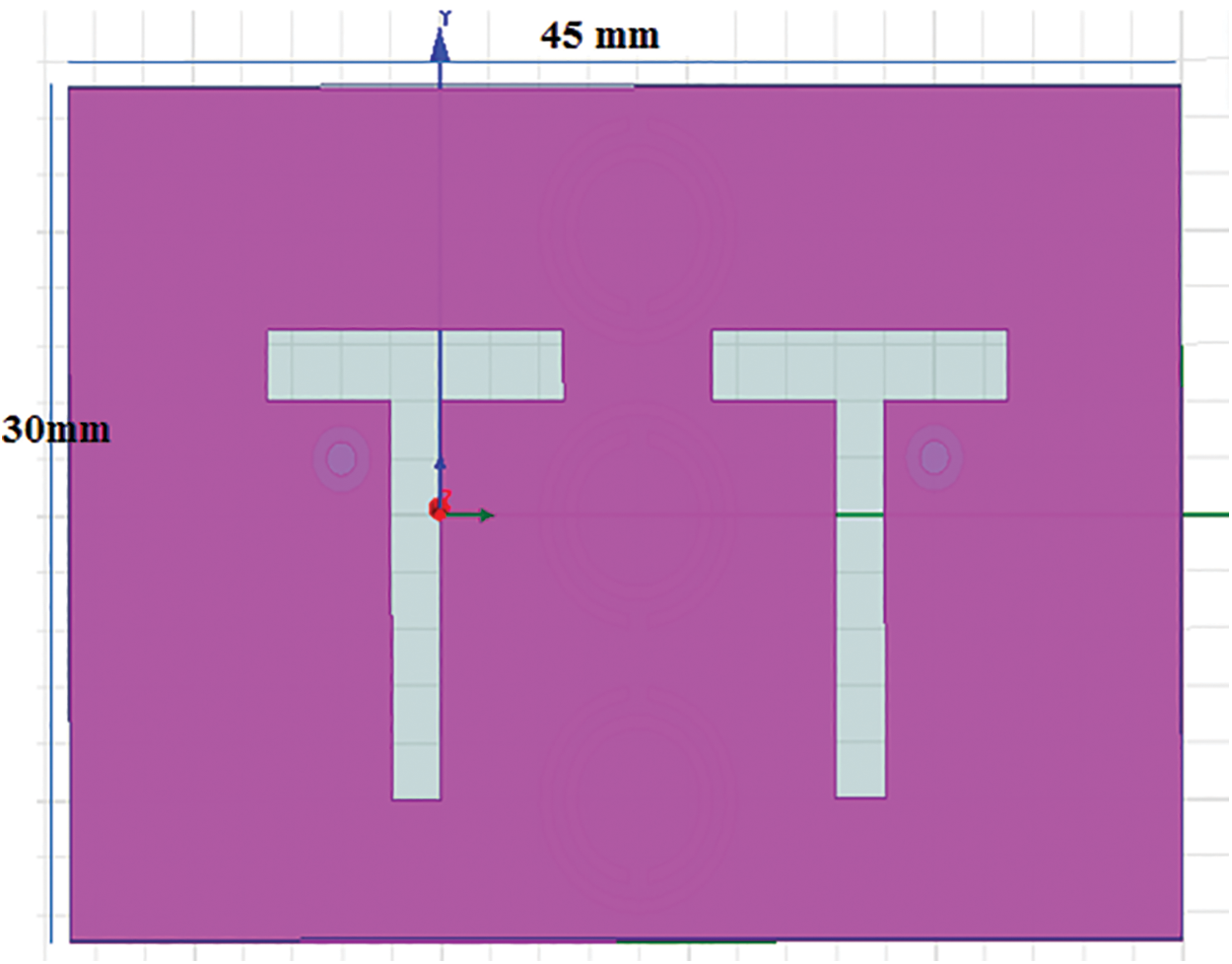
Figure 2: Two t-shaped antennas with a substrate 30 mm
The Federal communications authorize UWB communications between 3.1 and 10.6 GHz. Then the center frequency is calculated by using the formula value as 5.7 GHz. To minimize the antenna size, the effect on antenna efficiency of different parameters is noted first, and no particular parameter is found to affect just one antenna character. The antenna resonance frequency varies considerably due to the reduction in size and the feedback leakage bandwidth reduces. Also, it no longer displays an omnidirectional radiation pattern. The patch, in this case, is similar to a capacitive load, which may reduce the antenna’s resonance frequency. Consequently, a significant size reduction can be accomplished without altering the radiation pattern by accurately selecting the patch’s dimension. The Ansoft HFSS is used to direct the development and antenna geometry is to minimize experimental cut-and-trying process cycles. For MIMO applications on impedances and radiation patterns of the array, the T-shaped antenna array is planned.
When several antennas are mounted with space less than λ/2, the radiation efficiency of antenna and channel capability is often severely degraded by reciprocal coupling. To further separate the MIMO antenna, the lower and the top bands are fitted with an inverted T-slot and a revolving resonant line extension. The feed lines then comprise two T-slits, which achieve greater impedance. A high isolation MIMO dual-band antenna with improved bandwidth for WLAN will finally be acquired using the Split Ring Resonator (SRR) in the ground plane. Here, the operating frequency was taken between 3.1 and 10.6 GHz for analysis Eq. (1) :
where W is the width of the patch,
where
where
where
where
Where
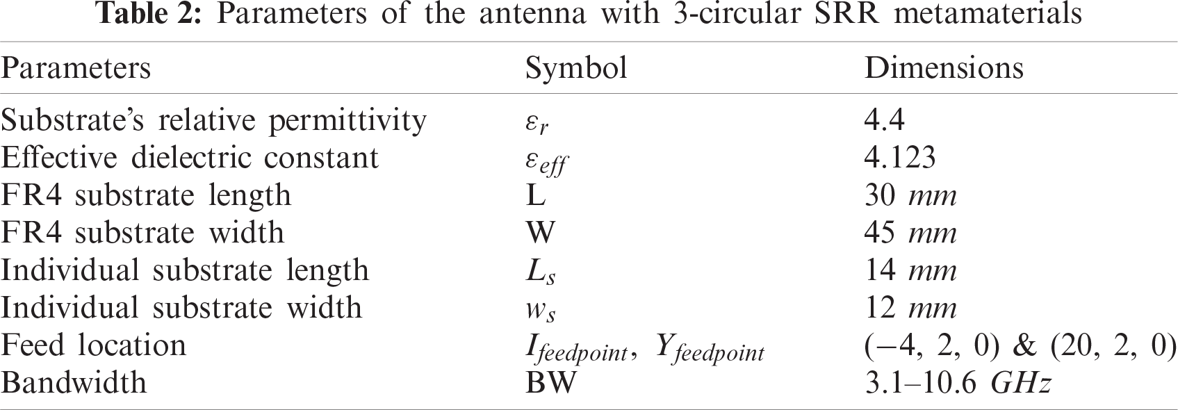
The parameter of the suggested antenna is depicted below.
The performance of Two T-shaped planar antennae depends significantly on the feed point location, which can be located at the
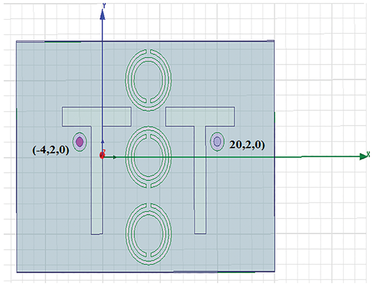
Figure 3: Co-axial probe feed location
The simulation and optimization were carried out with a T-shape microstrip antenna’s configuration with an operating frequency of between 3.1 and 10.6 MHz. Then, the circular metamaterial 3-SRR was applied to the antenna base to expand its bandwidth, as shown in Fig. 4.
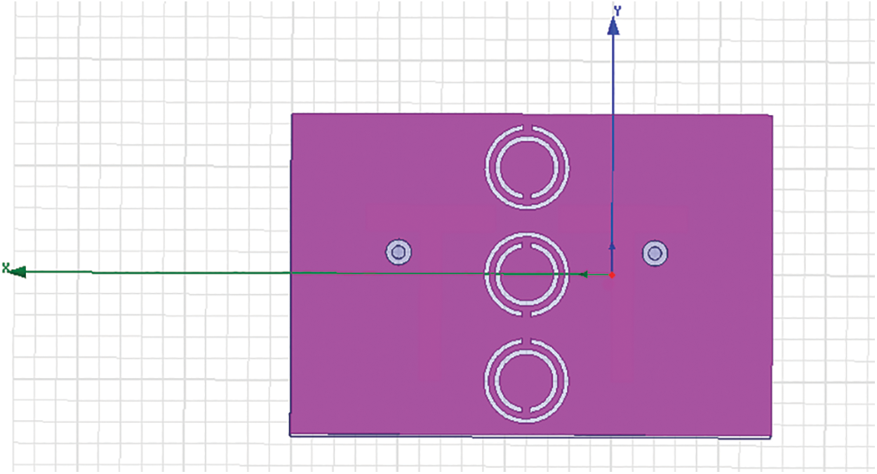
Figure 4: SRR circular type
The projected configuration of planar two T-shaped MIMO antennas with 3-circular SRR is shown in Fig. 5 in the 3-D model. The compression is rendered with co-axial feed for these two T-shaped antennas.
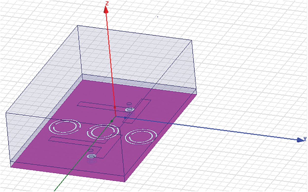
Figure 5: Representation of proposed design in 3D model
In this step, initial simultaneous use of the measurements of the T-shaped antenna was carried out. Such optimization was again carried out to achieve the final simulation’s effects, including optimizing the number of three circular SRR metamaterial on the ground level, where three SRR metamaterials were applied to the final antenna configuration.
Fig. 6 displays the return loss results of antenna simulation after optimization. It is shown that a return loss of less than −10 dB can be obtained during the simulation.
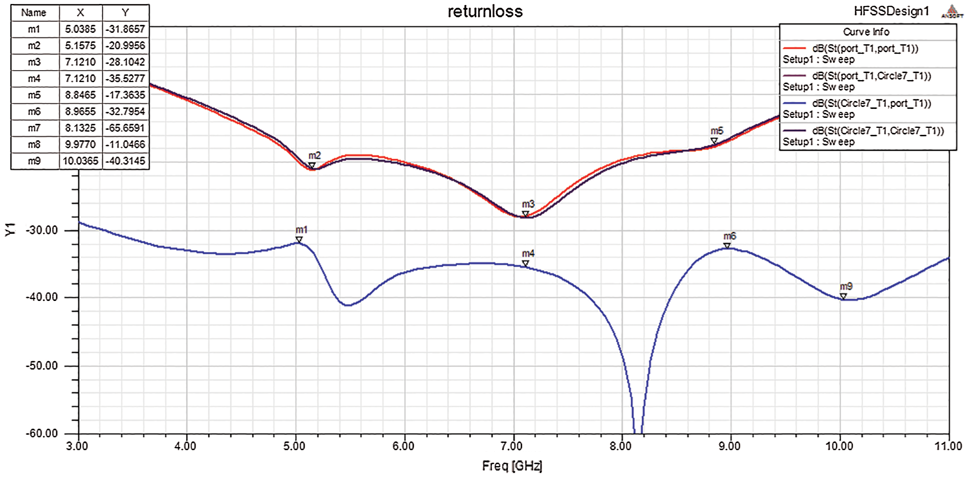
Figure 6: Return loss analysis of the proposed design
It is determined using a particular frequency spectrum that the voltage signal to noise ratio gives power capabilities. Fig. 7 clearly outlines the examination of VSWR.
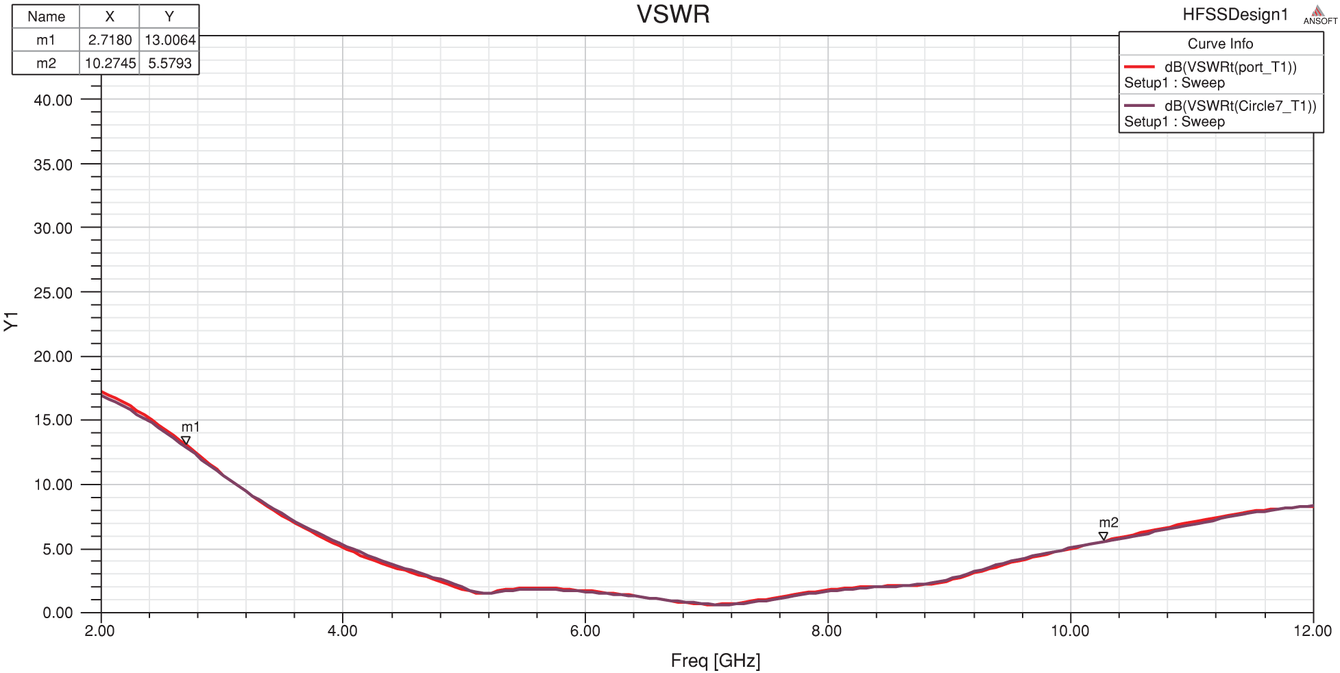
Figure 7: Analysis of Voltage signal to noise ratio
Fig. 8 indicates the designed radiation pattern at various wavelengths. The given diagram shows the radiation pattern of the 3-SRR antenna as a directional radiation pattern, which was noticed by the simulation. The radiation pattern arising from the simulation thus satisfied the required initial criterion, which is directional. The radiation pattern of the antenna is defined during simulation to add the ISM Band MIMO. The antenna continuously irradiates radio wave radiation in all directions in one plane, with the radiated power falling at zero on an antenna point by a height above and below the surface. This can be attuned in any orientation.
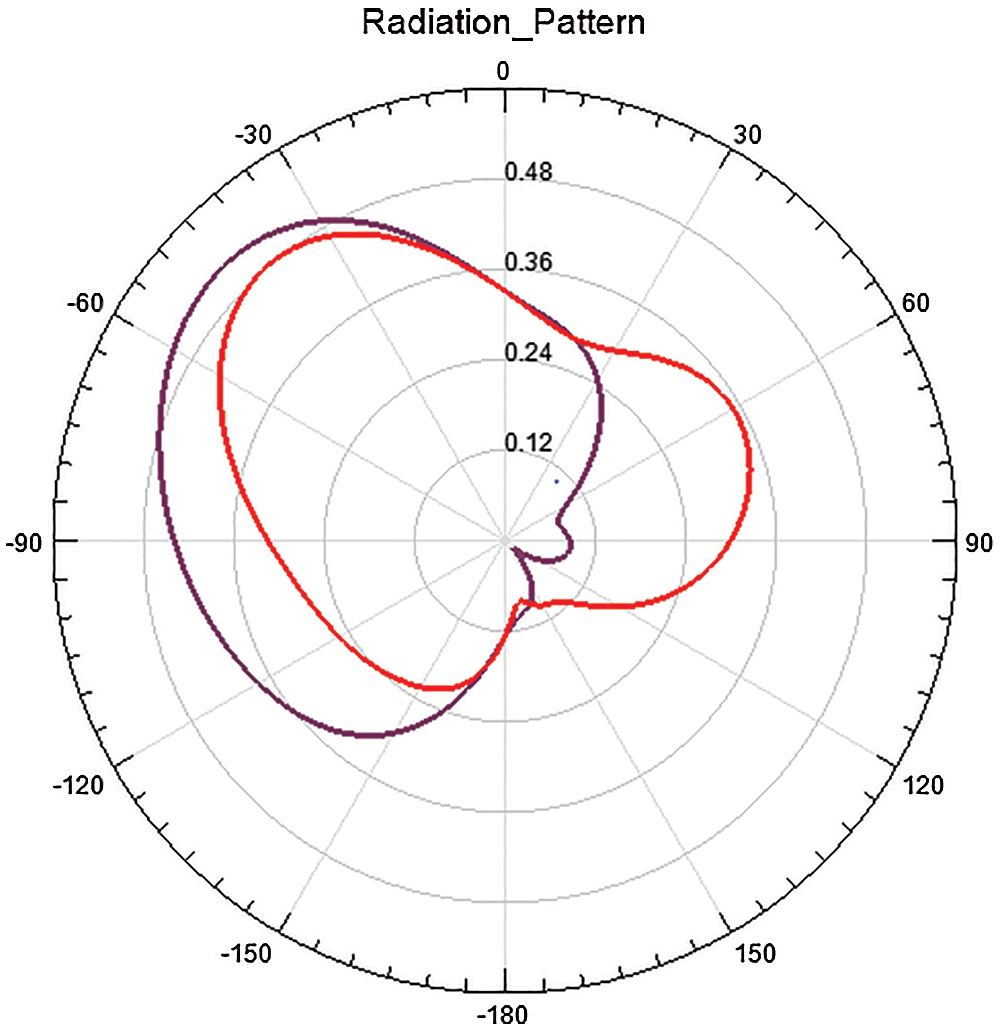
Figure 8: The radiation pattern of the suggested model
Fig. 9 shows that there is a gain of 1.92 dB on an antenna of four three-strand metamaterials. In the meantime, Figs. 8 and 9 demonstrate the antenna radiation model of 3-SRR simulation metamaterials.
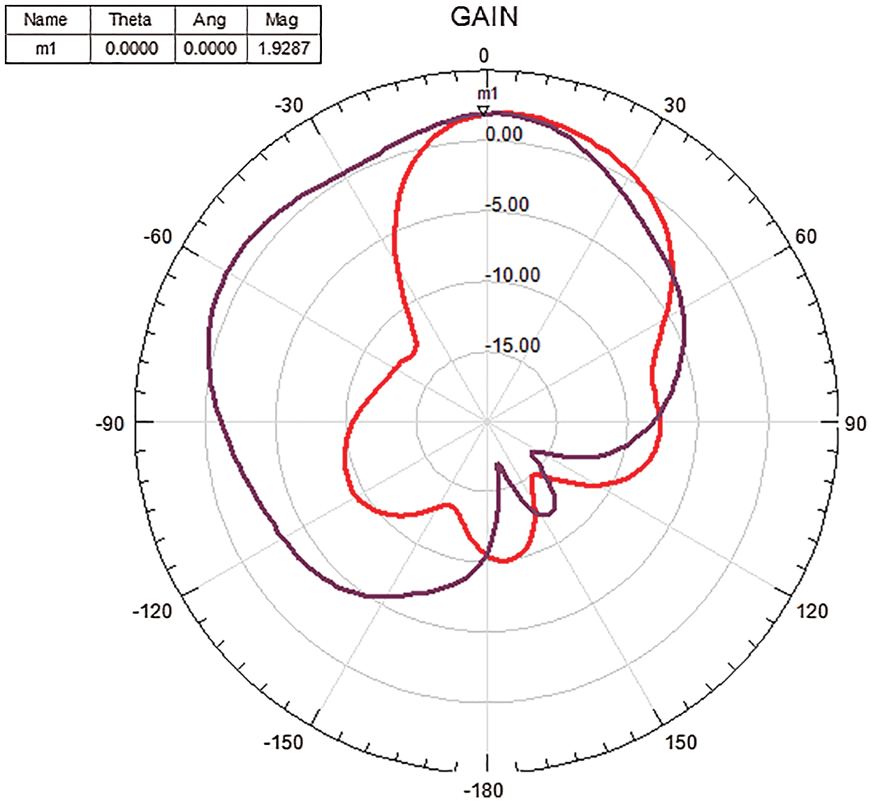
Figure 9: Radiation pattern gain
The Envelope Correlation Coefficient (ECC) is another significant parameter of the MIMO antennas. An ECC can be used to test the complexity of a MIMO scheme. ECC = 0 means the antennas are decoupled completely, as ECC = 1 means they are short-circuited essentially (Fig. 10). Here, the ECC value seems to be 0.00185, making it decoupled.
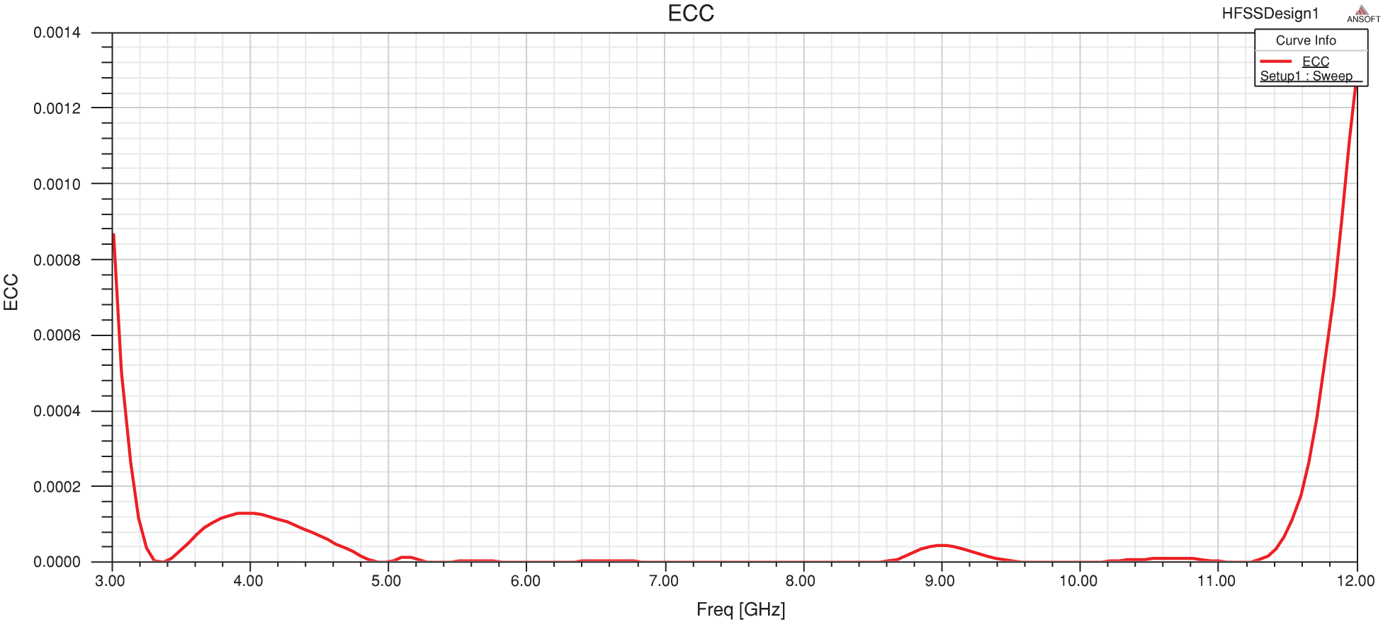
Figure 10: Envelope correlation co-efficient
By adjusting the feed point settings, the output of a planar T-shaped antenna is controlled. The return loss, VSWR, and radiation pattern were measured at each feeding point location. It is exposed that the feed point position selection by reducing the optimal return loss and other restraining aspects will significantly increase the gain, directivity, and effectiveness of an antenna patch. In this part of the research work, the UWB band could be achieved using three circular type SRR in the ground plane. In future, this work can be further extended by enhancing the bandwidth by means of varying the shape and materials used.
Funding Statement: The authors received no specific funding for this study.
Conflicts of Interest: The authors declare that they have no conflicts of interest to report regarding the present study.
1. A. Biswas and V. R. Gupta, “Design and development of low-profile MIMO antenna for 5G new radio smartphone applications,” Wireless Personal Communications, vol. 111, no. 3, pp. 1695–1706, 2020. [Google Scholar]
2. X. Chen, L. Han, X. Chen and W. Zhang, “Dual-band circularly polarized antenna using mu-negative transmission lines,” IEEE Antennas and Wireless Propagation Letters, vol. 17, no. 7, pp. 1190–1194, 2018. [Google Scholar]
3. T. Cheng, W. Jiang, S. Gong and Y. Yu, “Broadband SIW cavity-backed modified dumbbell-shaped slot antenna,” IEEE Antennas and Wireless Propagation Letters, vol. 18, no. 5, pp. 936–940, 2019. [Google Scholar]
4. A. Desai and P. Nayeri, “A wideband dual-polarized stacked microstrip patch antenna with a dumbbell shaped aperture,” in 2019 United States National Committee of URSI National Radio Science Meeting, Boulder, CO, USA, pp. 1–2, 2019. [Google Scholar]
5. S. Hota, S. Baudha, B. Mangaraj and M. Varun Yadav, “A novel compact planar antenna for ultra-wideband application,” Journal of Electromagnetic Waves and Applications, vol. 34, no. 1, pp. 116–128, 2020. [Google Scholar]
6. A. Desai, T. Upadhyaya, M. Palandoken and C. Gocen, “Dual-band transparent antenna for wireless MIMO system applications,” Microwave and Optical Technology Letters, vol. 61, no. 7, pp. 1845–1856, 2019. [Google Scholar]
7. L. Kang, H. Li, X. Wang and X. Shi, “Compact offset microstrip-fed MIMO antenna for band-notched UWB applications,” IEEE Antennas and Wireless Propagation Letters, vol. 14, pp. 1754–1757, 2015. [Google Scholar]
8. Z. Li, C. Yin and X. Zhu, “Compact UWB MIMO Vivaldi antenna with dual band-notched characteristics,” IEEE Access, vol. 7, pp. 38696–38701, 2019. [Google Scholar]
9. C.-M. Luo, J.-S. Hong and L.-L. Zhong, “Isolation enhancement of a very compact UWB-MIMO slot antenna with two defected ground structures,” IEEE Antennas and Wireless Propagation Letters, vol. 14, pp. 1766–1769, 2015. [Google Scholar]
10. A. Iqbal, O. A. Saraereh, A. W. Ahmad and S. Bashir, “Mutual coupling reduction using F-shaped stubs in UWB-MIMO antenna,” IEEE Access, vol. 6, pp. 2755–2759, 2017. [Google Scholar]
11. H. J. Basherlou, N. O. Parchin and R. A. Abd-Alhameed, “MIMO monopole antenna design with improved isolation for 5G Wi-Fi applications,” International Journal of Electrical and Electronic Science, vol. 7, no. 12, pp. 1–5, 2019. [Google Scholar]
12. S. Kumar, G. H. Lee, D. H. Kim, W. Mohyuddin, H. C. Choi et al., “Multiple-input-multiple-output/diversity antenna with dual band-notched characteristics for ultra-wideband applications,” Microwave and Optical Technology Letters, vol. 62, no. 1, pp. 336–345, 2020. [Google Scholar]
13. R. Chandel, A. K. Gautam and K. Rambabu, “Design and packaging of an eye-shaped multiple-input-multiple-output antenna with high isolation for wireless UWB applications,” IEEE Transactions on Components, Packaging and Manufacturing Technology, vol. 8, no. 4, pp. 635–642, 2018. [Google Scholar]
14. R. Gurjar, D. K. Upadhyay, B. K. Kanaujia and K. Sharma, “A novel compact self-similar fractal UWB MIMO antenna,” International Journal of RF and Microwave Computer-Aided Engineering, vol. 29, no. 3, pp. e21632, 2019. [Google Scholar]
15. A. Ghosh, S. Chakraborty, S. Chattopadhyay, A. Nandi and B. Basu, “Rectangular microstrip antenna with dumbbell-shaped defected ground structure for improved cross polarised radiation in wide elevation angle and its theoretical analysis,” IET Microwaves, Antennas & Propagation, vol. 10, no. 1, pp. 68–78, 2016. [Google Scholar]
16. J. Nasir, M. H. Jamaluddin, M. Khalily, M. R. Kamarudin, I. Ullah et al., “A reduced size dual port MIMO DRA with high isolation for 4G applications,” International Journal of RF and Microwave Computer Aided Engineering, vol. 25, no. 6, pp. 495–501, 2015. [Google Scholar]
17. G. Ali Sarkar, S. Ballav, A. Chatterjee, S. Ranjit and S. K. Parui, “Four element MIMO DRA with high isolation for WLAN applications,” Progress in Electromagnetics Research, vol. 84, pp. 99–106, 2019. [Google Scholar]
18. I. Aggarwal, M. R. Tripathy and S. Pandey, “Metamaterial inspired multiband slotted antenna for application in IoT band,” in 2016 Online Int. Conf. on Green Engineering and Technologies, Coimbatore, India, pp. 1–4, 2016. [Google Scholar]
19. I. Kaur, A. K. Singh, J. Makhija, S. Gupta and K. K. Singh, “Designing and analysis of microstrip patch antenna for UWB applications,” in 3rd Int. Conf. on Internet of Things: Smart Innovation and Usages, Bhimtal, India, pp. 1–3, 2018. [Google Scholar]
20. Z.-Y. Zhang, X.-D Yang, S.-L. Zuo and G. Fu, “Wideband omnidirectional printed dipole antenna with dumbbell-shaped open sleeve for wireless communication applications,” IET Microwaves, Antennas & Propagation, vol. 8, no. 15, pp. 1299–1304, 2014. [Google Scholar]
21. K. S. L. Al-Badri and F. Q. Muhammad, “Design and analysis quad-band patch antenna for wireless communication,” Samarra Journal of Pure and Applied Science, vol. 2, no. 1, pp. 25–34, 2020. [Google Scholar]
22. K. Viswanadha and N. S. Raghava, “Design and analysis of a multi-band flower shaped patch antenna for WLAN/WiMAX/ISM band applications,” Wireless Personal Communications, vol. 112, no. 2, pp. 863–887, 2020. [Google Scholar]
23. A. Puran and Ş.T. İmeci, “Design and analysis of compact dual resonance patch antenna,” Heritage and Sustainable Development, vol. 2, no. 1, pp. 38–45, 2020. [Google Scholar]
24. G. Kumar and C. Kumar, “Design and analysis of U-slot mircostrip patch antenna for mobile communication at 60 Ghz,” Acta Technica Corviniensis-Bulletin of Engineering, vol. 3, no. 1, pp. 35–38, 2020. [Google Scholar]
25. W. Balani, M. Sarvagya, A. Samasgikar, T. Ali and P. Kumar, “Design and analysis of super wideband antenna for microwave applications,” Sensors, vol. 21, no. 2, pp. 477, 2021. [Google Scholar]
26. H. Li, Z. T. Miers and B. K. Lau, “Design of orthogonal MIMO handset antennas based on characteristic mode manipulation at frequency bands below 1 GHz,” IEEE Transactions on Antennas and Propagation, vol. 62, no. 5, pp. 2756–2766, 2014. [Google Scholar]
27. K. Sumathi and M. Abirami, “Hexagonal shaped fractal MIMO antenna for multiband wireless applications,” Analog Integrated Circuits and Signal Processing, vol. 104, no. 3, pp. 277–287, 2020. [Google Scholar]
28. X. Zhao, S. Riaz and S. Geng, “A reconfigurable MIMO/UWB MIMO antenna for cognitive radio applications,” IEEE Access, vol. 7, pp. 46739–46747, 2019. [Google Scholar]
 | This work is licensed under a Creative Commons Attribution 4.0 International License, which permits unrestricted use, distribution, and reproduction in any medium, provided the original work is properly cited. |