DOI:10.32604/cmc.2021.018241
| Computers, Materials & Continua DOI:10.32604/cmc.2021.018241 | |
| Article |
Simulation of Lumbar Spinal Stenosis Using the Finite Element Method
1Department of Mathematics, Faculty of Science, Khon Kaen University, Khon Kaen, 40002, Thailand
2Department of Mathematics, Faculty of Science, Mahasarakham University, Mahasarakham, 44150, Thailand
*Corresponding Author: Kamonchat Trachoo. Email: kamonchat.t@msu.ac.th
Received: 02 March 2021; Accepted: 04 May 2021
Abstract: Lumbar spine stenosis (LSS) is a narrowing of the spinal canal that results in pressure on the spinal nerves. This orthopedic disorder can cause severe pain and dysfunction. LSS is a common disabling problem amongst elderly people. In this paper, we developed a finite element model (FEM) to study the forces and the von Mises stress acting on the spine when people bend down. An artificial lumbar spine (L3) was generated from CT data by using the FEM, which is a powerful tool to study biomechanics. The proposed model is able to predict the effect of forces which apply to the lumbar spine. In addition, FEM allows us to investigate the tests into the lumbar spine instead of applying the tests to the real spine in humans. The proposed model is highly accurate and provides precise information about the lumbar spine (L3). We investigate the behavior of humans in daily life which effects to the lumbar spine in a normal person and a patient with LSS. The computational results revealed high displacement levels around the spinal canal and lower displacement levels in the spinal body when bending down. The total displacement of the axial load in a normal person was higher when compared with patients with LSS. Higher degree bends resulted in a lower total displacement when compared with lower degree bends, while the von Mises stress decreased as the bending degree increased.
Keywords: Lumbar spinal stenosis; finite element method; mathematical model; von Mises stress
As the population is aging, the incidence of orthopedic problems among elderly people such as osteoporosis, osteonecrosis, primary and secondary bone tumors, scoliosis, low bone density, osteoarthritis, Paget’s disease, and gout is increasing. These orthopedic disorders can cause severe pain and dysfunction, particularly when affecting the spine. The spine or backbone is an important part of the human body because it supports the body structure and connects the nervous system. The spine is composed of the cervical, thoracic, lumbar, sacrum, and coccyx. The lumbar spine consists of five spinal columns (L1-L5) and supports most of the upper part of the body while also protecting the spinal cord and nerves from injury. Lumbar spinal stenosis (LSS) is a common disease found in the elderly population all around the world [1,2]. This disease was first described in the 1950s [3]. LSS occurs as a result of narrowing of the spinal canal, which results in pressure on the spine and the spinal nerve root. The pressure causes pain in the back, buttocks, and legs [4]. It may also cause loss of sensation and weakness in the feet and legs, as well as sexual dysfunction. Therefore, in order to reduce the incidence of LSS and to develop appropriate therapeutic interventions, there is a need to understand the biomechanics of LSS.
Finite element simulation models (FEM) are now increasingly used to explore the biomechanical properties of the spine and to guide surgical interventions [5–9]. Xu et al. [10] utilized this method to develop five FEMs of the lumbar spines (L1-L5). They showed that the models confirmed that the computational results were consistent with the experimental results. Finley et al. [11] developed an open-access FEM of the human lumbar spine for both healthy and degenerating lumbar spine. These models could be used to study the biomechanics of the lumbar spine. Gupta et al. [12] used finite element analysis to model the internal stress and strain in the craniovertebral junction (CVJ) region caused by different implants. On the other hand, Chung et al. studied the effect of implanting an artificial disc on L4 and L5 using the FEM [13], and Zhong et al. [14] also used this model to evaluate the impact of a new cage as a space holder on the lumbar spine. A number of research studied about the von Mises stress and total displacement of spine [15–18]. The von Mises stress is often used to analyze the risk of developing burst fracture in bones of various grades [19]. It is also used to interpret the six stress components acting on the materials [20]. However, to our knowledge, no FEM has yet been developed evaluating the stress and strain in LSS.
This study aimed to develop a FEM to compare the effect of the total displacement and von Mises stress in a normal person and in a patient with LSS while bending down using an artificial lumbar spine by using a lumbar vertebra model reconstructed from a computed tomography (CT) scan.
2.1 Construction of the Lumbar Vertebra Model
A two-dimensional and three-dimensional model of the third lumbar (L3) vertebra was constructed using the CT data of a human lumbar spine. The CT data were taken from a healthy person and a patient with LSS. The complete geometry of a healthy lumbar spine is illustrated in Fig. 1, and the geometry of a patient with LSS is illustrated in Fig. 2. The finite element representation of the lumbar spine models was obtained by subdividing the solids into a mesh of triangular elements. The bone dimensions were 7.02 cm × 7.70 cm × 4.5 cm. The mesh of the normal lumbar spine geometry consisted of 22,630 elements, and the mesh of lumbar spinal with stenosis consisted of 19,008 elements, as shown in Fig. 3.
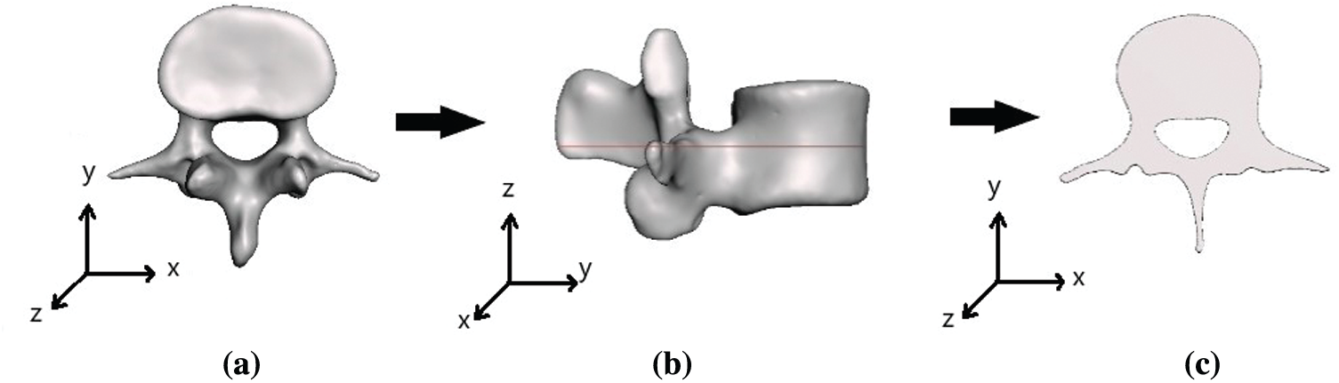
Figure 1: (a), (b) Three-dimensional and (c) two-dimensional geometry of a normal lumbar spine (L3)
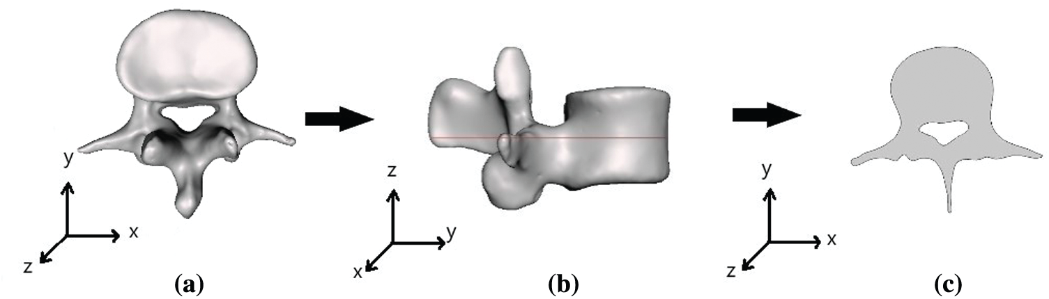
Figure 2: (a), (b) Three-dimensional and (c) two-dimensional geometry of lumbar spinal (L3) with stenosis
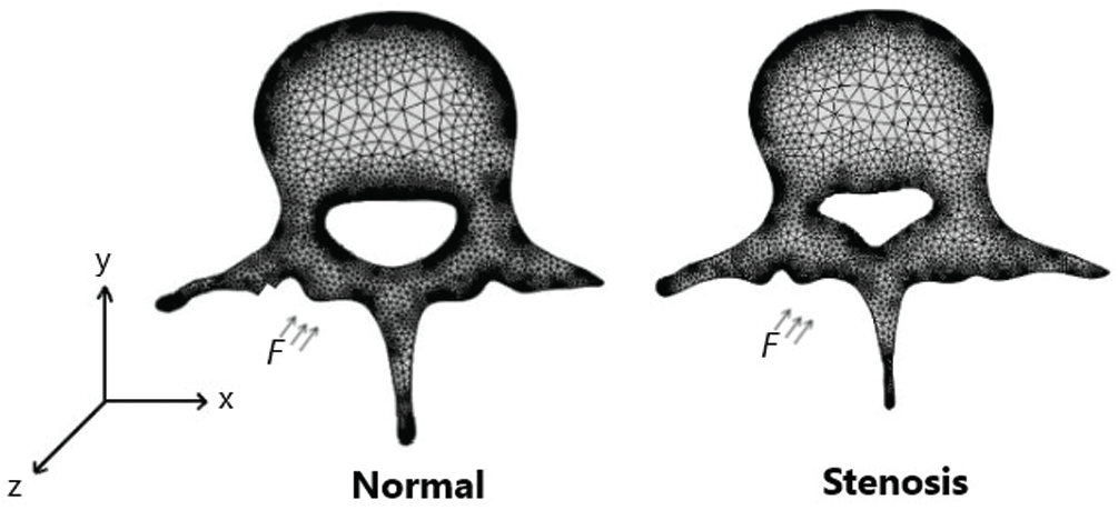
Figure 3: Mesh patient geometry of a normal lumbar spine and a lumbar spinal with stenosis
The lumbar spine was assumed to consist of von Mises elastoplastic material. According to the principles of continuum mechanics, the displacement, stress fields, and stress equilibrium in the lumbar spine can be defined using the following equations;
where
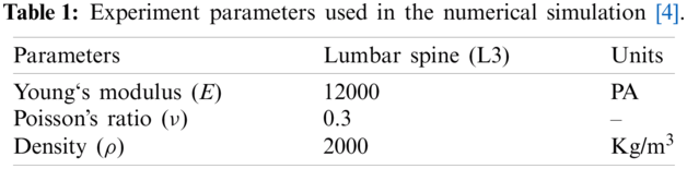
The parameters used during the numerical simulation are shown in Tab. 1. For the domain, shown in Fig. 3, we imposed three boundary conditions based on the axial load on a person with a normal spine and a person with LSS while bending down. The outer boundaries of the lumbar spine for both normal person and LSS patients were fixed to prevent translation and rotation of the domain. The inner boundaries of the domains were not fixed because this study investigated the effect of the force on the spinal structure.
2.3 Effect of Forces Applied on the Human Lumbar Spine
The effect of forces applied on the human lumbar spine was simulated based on an average woman’s weight of 58.58 Kg. The forces on the human body when a person bends down at 30-degrees (
(I)
(II)
(III)
The FEM was used to find the numerical solution of the boundary value by multiplying Eq. (1) with the weighting function
From symmetry of
Substituting Eq. (3) into Eq. (2), we obtained
The divergence theorem was then applied as follows
Eq. (5) was then substituted into Eq. (4) to obtain
The surface fraction boundary condition was explained by the equation
which is equivalent to
From Eq. (8) and Eq. (6), we obtained
Since
we arranged Eq. (9) to
The third equation was substituted in the system (1) into Eq. (10) to obtain the equation
We then assumed that
Eq. (11) was subsequently rearranged to obtain
Hence, the variational statement for the boundary value problem was finally stated as follows:
Find
where
In order to find the numerical solution of this variational boundary value problem, we imposed this problem in an
where
Eq. (14) was substituted into Eq. (13). Since
which represented a system of 2N equations in terms of unknowns
Finally, this problem was solved using the quasi-Newton method. The computational analysis was performed using the COMSOL multiphysics (COMSOL Inc., MA, USA).
The effects of the total displacement and von Mises stress on a patient with a normal lumbar spine and a patient with LSS while bending down are illustrated in Figs. 2 and 3. Figs. 4 to 6 show the total displacement of the axial load of the LSS patient and for a person without disease while bending down at 30, 45, and 60 degrees, respectively. The findings of this study indicate that the highest displacement occurs around the spinal canal and the lowest displacement occurs around the external part of the lumbar spine. This means that when a human bends down, there are some parts of the spine perturbing, especially in the areas around the spinal canal.
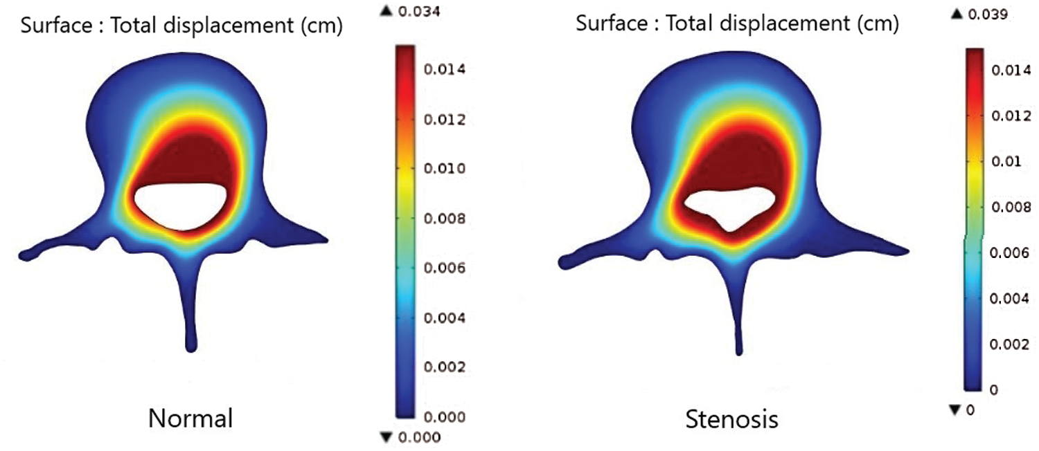
Figure 4: Comparison of the total displacement of the axial load in a normal patient and in a patient with LSS while bending down at 30 degrees
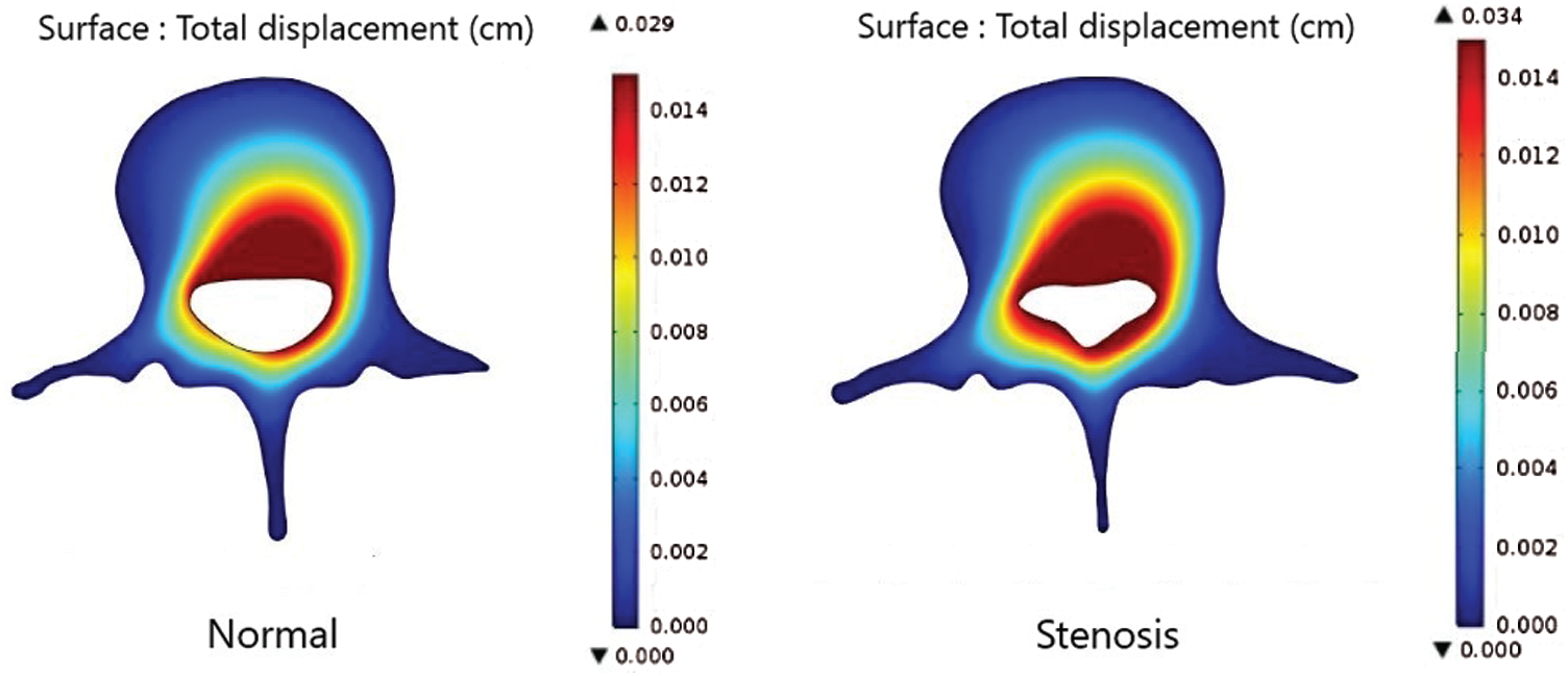
Figure 5: Comparison of the total displacement of the axial load in a normal patient and in a patient with LSS while bending down at 45 degrees
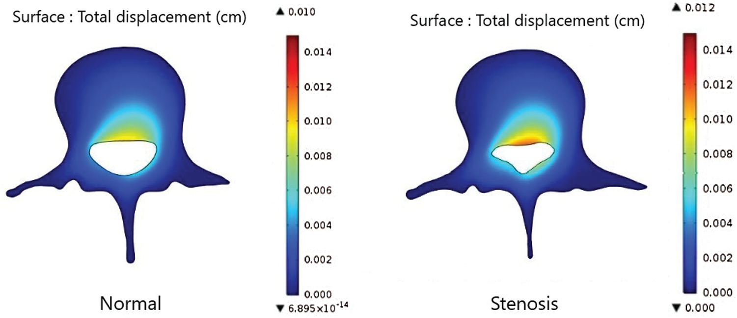
Figure 6: Comparison of the total displacement of the axial load in a normal patient and in a patient with LSS while bending down at 60 degrees
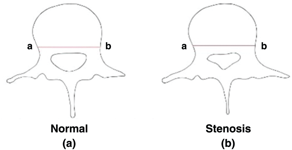
Figure 7: Line a-b illustrates the cross-sectional domain of the lumbar spine in a normal person and a patient with LSS
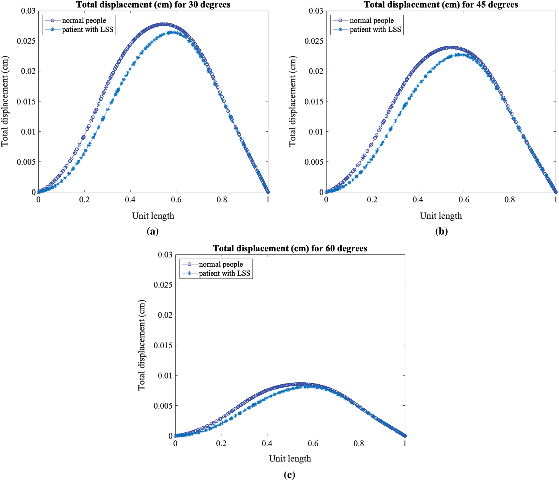
Figure 8: Total displacement of the axial load in a patient with LSS and a person without disease while bending down at (a) 30 degrees, (b) 45 degrees, and (c) 60 degrees
The total displacement was then compared using the cross-section line of the domain of the lumbar spine, as shown in Fig. 7. We then transformed the length of the cross-section line into a unit length. The findings of this analysis indicate that the total displacement is higher in a person with a normal spine when compared with a person with LSS, as illustrated in Fig. 8. Moreover, as the bending degree increased, the total displacement decreased, as shown in Fig. 9. This means that a smaller degree bend resulted in high perturbation on parts of the spine and affected the displacement of the lumbar spine.
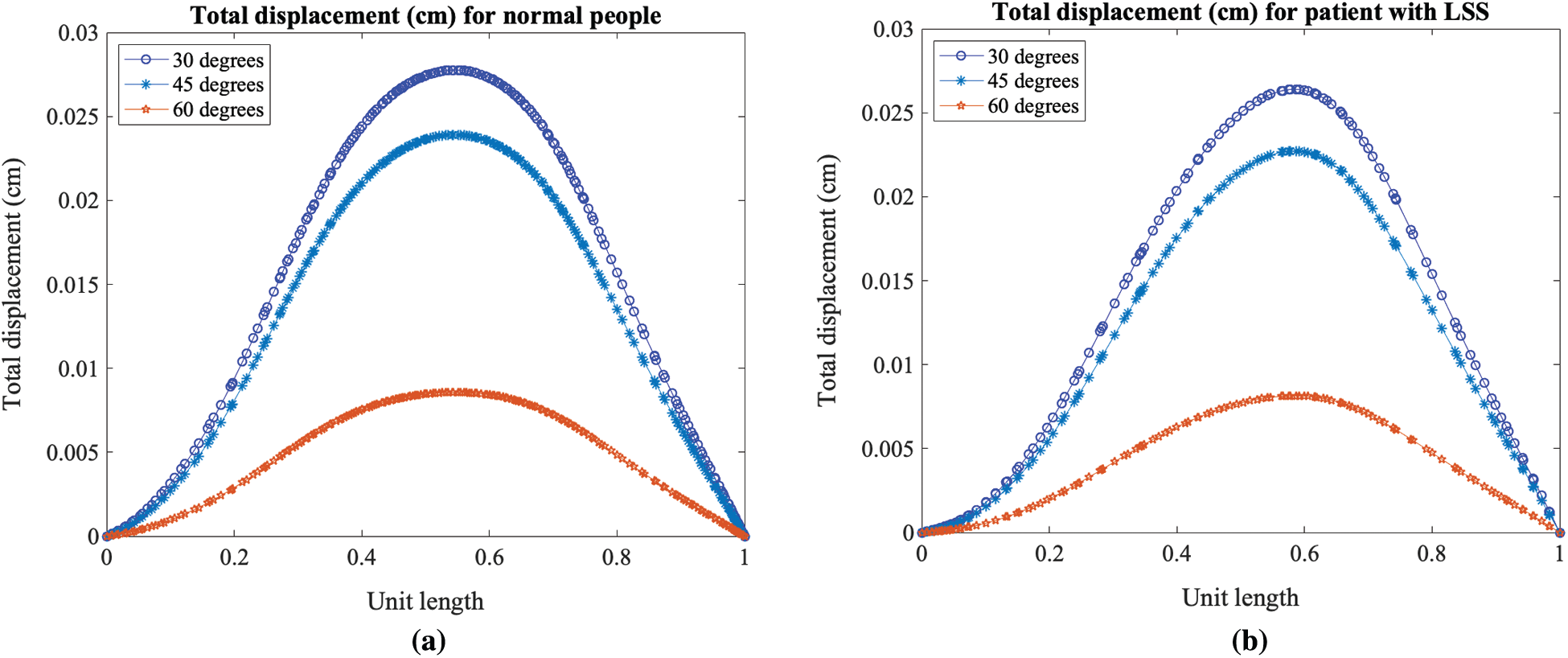
Figure 9: Total displacement profile for the three different bending degrees, in (a) a person with a normal lumbar spine and (b) a patient with LSS
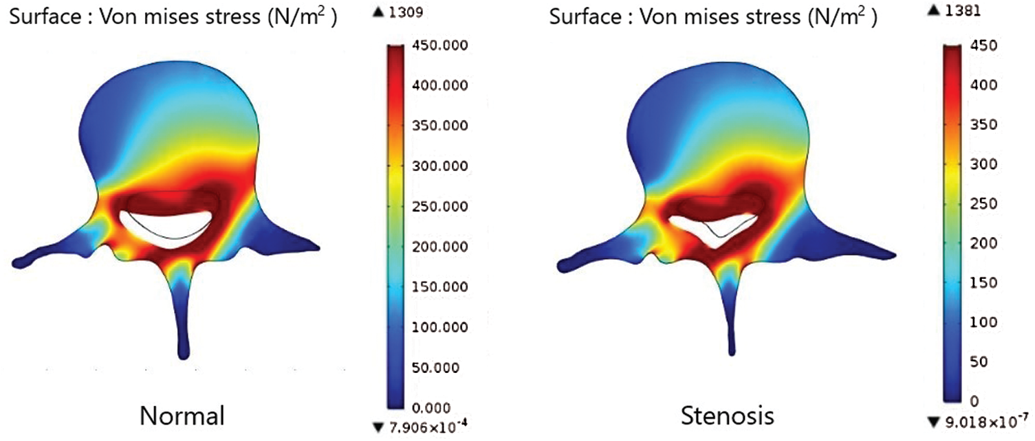
Figure 10: Comparison of the von Mises stress on the axial load of the lumbar spinal in a normal patient and in a patient with LSS while bending down at 30 degrees
Figs. 10–12 show the von Mises stress of the axial load in the lumbar spine in a normal person and a patient with LSS when both people bend down at 30, 45, and 60-degrees. The results indicate a high level of stress closer to the spine canal. Fig. 13 shows the von Mises stress of the lumbar spine in a normal person and a patient with LSS at the cross-section lines described in Fig. 7. The results indicate higher von Mises stress levels on the axial load of the lumbar spine in a normal person when compared with a patient with LSS. In Fig. 13, the cross-sectional line was transformed into a unit length. The cross-sectional von Mises stress analysis indicated that the left half of the lumbar spine has higher stress levels when compared with the right side. Moreover, the von Mises stress in both normal and diseased spines increased as the bending degree decreased, as shown in Fig. 14.
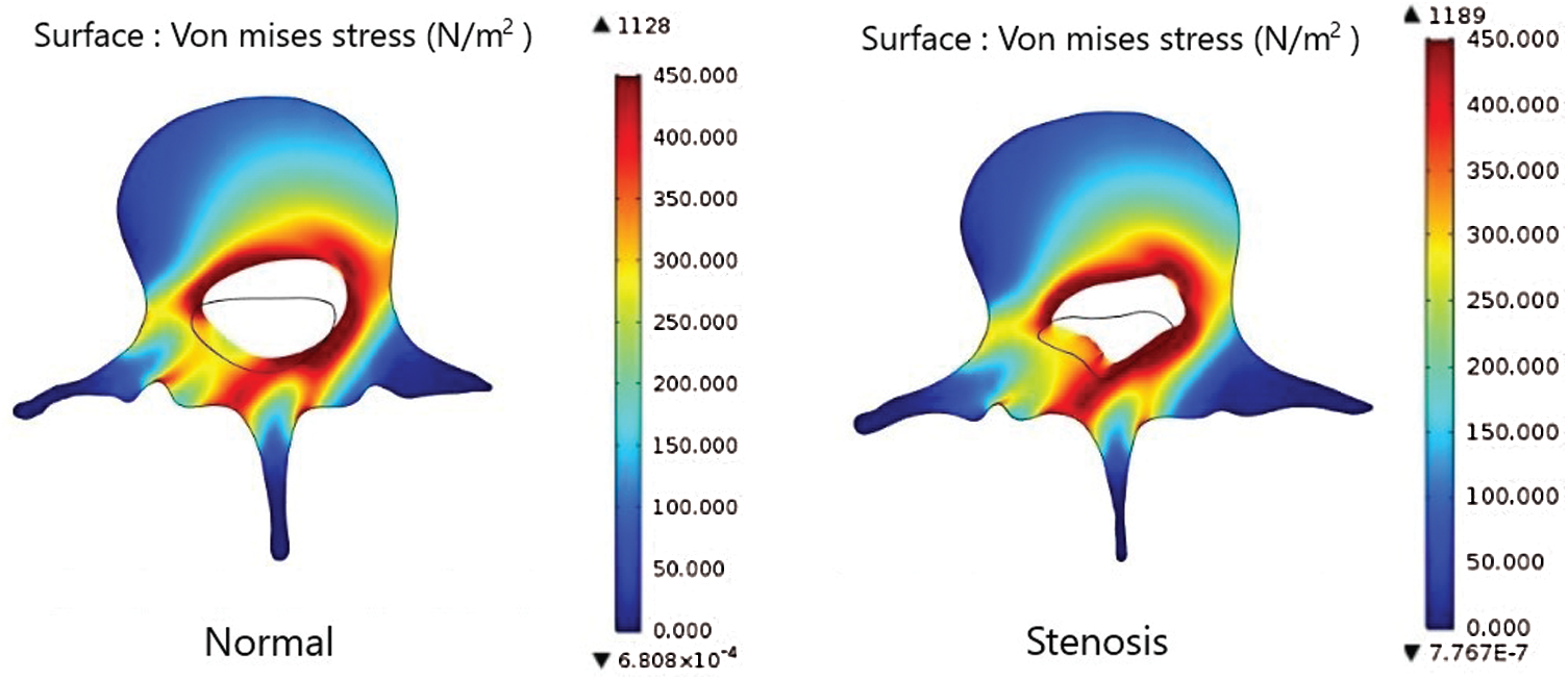
Figure 11: Comparison of the von Mises stress on the axial load of the lumbar spinal in a normal patient and in a patient with LSS while bending down at 45 degrees
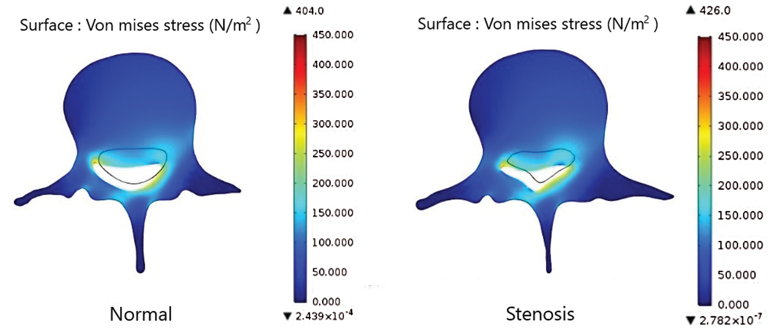
Figure 12: Comparison of the von Mises stress on the axial load of the lumbar spinal in a normal patient and in a patient with LSS while bending down at 60 degrees
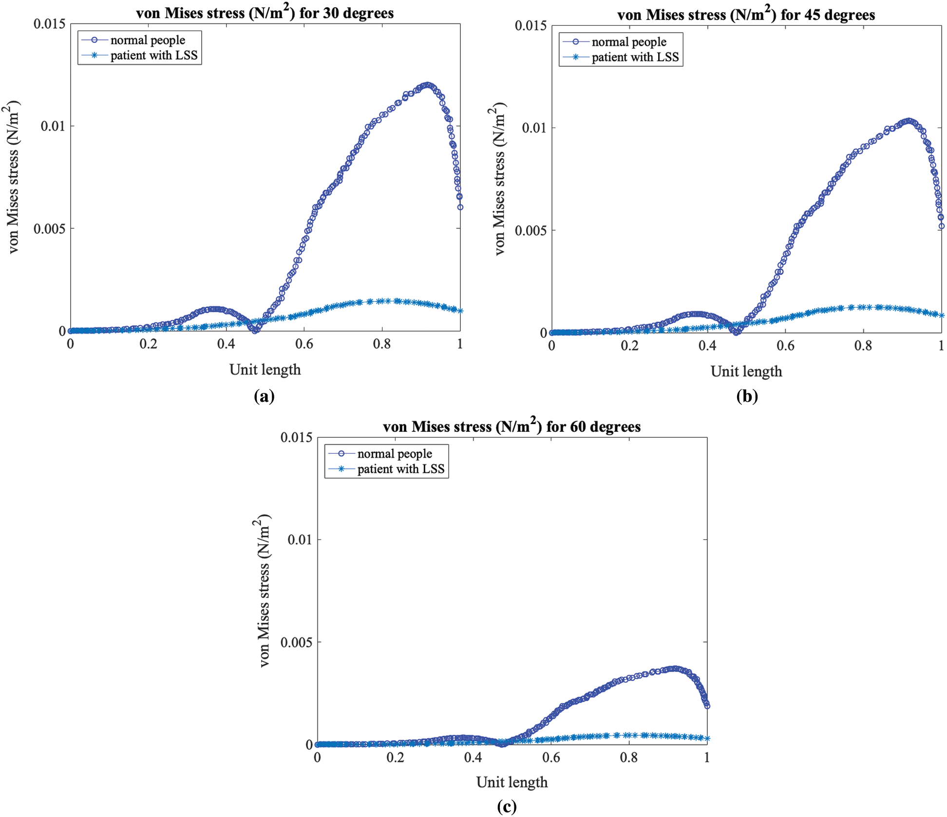
Figure 13: Von Mises stress on the axial load of a normal patient and a patient with LSS while bending down at (a) 30 degrees, (b) 45 degrees, and (c) 60 degrees
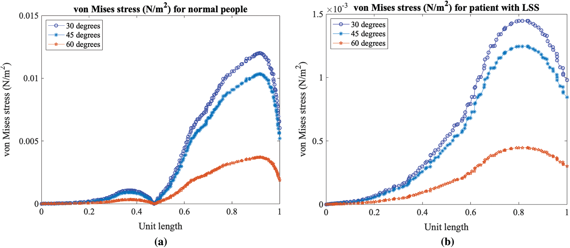
Figure 14: Von Mises stress profile at three different bending degree levels for (a) a person with a normal spine and (b) a patient with LSS
A mathematical model of the lumbar spine has been developed to study the total displacement and von Mises stress between a normal person and a patient with LSS by using the finite element method. Numerical simulations were carried out to evaluate the effect of the forces on the lumbar spine when people bend down. The results showed that high displacement levels occurred around the spinal canal, while a lower displacement was observed around the periphery of the human spine. The total displacement of the axial load in a normal person was higher when compared with a patient with LSS. Higher degree bends resulted in a lower total displacement when compared with lower degree bends, while the von Mises stress decreased as the bending degree increased.
Acknowledgement: The authors are thankful to the reviewers. This research was supported by the Basic Research Fund of Khon Kaen University. Moreover, this research was also financially supported by Mahasarakham University. The authors also would like to thank the Department of Civil Engineering, Faculty of Engineering, Khon Kaen University for providing the COMSOL Multiphysics package.
Funding Statement: This research was supported by the Basic Research Fund of Khon Kaen University. This research was also financially supported by Mahasarakham University.
Conflicts of Interest: The authors declare that they have no conflicts of interest to report regarding the present study.
1. R. Kalff, C. Ewald, A. Waschke, L. Gobisch and C. Hopf, “Degenerative lumbar spinal stenosis in older people—Current treatment options,” Deutsches Arzteblatt International, vol. 110, no. 37, pp. 613–624, 2013. [Google Scholar]
2. M. Szpalski and R. Gunzburg, “Lumbar spinal stenosis in the elderly: An overview,” European Spine Journal, vol. 12, pp. S170–S175, 2003. [Google Scholar]
3. J. Enlund, “Lumbar spinal stenosis,” Current Sports Medicine Reports, vol. 6, pp. 50–55, 2007. [Google Scholar]
4. A. M. Lafian and K. D. Torralba, “Lumbar spinal stenosis in older adults,” Rheumatic Disease Clinics of North America, vol. 44, no. 3, pp. 501–512, 2018. [Google Scholar]
5. M. Ho, “Bone and joints modelling with individualized geometric and mechanical properties derived from medical images,” Computer Modeling in Engineering & Sciences, vol. 4, no. 3&4, pp. 489–496, 2003. [Google Scholar]
6. G. Geethanjali and C. Sujatha, “Study of biomechanical response of human hand-arm to random vibrations of steering wheel of tractor,” Molecular & Cellular Biomechanics, vol. 10, no. 4, pp. 303–317, 2013. [Google Scholar]
7. B. Yang, H. Sun, A. Wang and Q. Wang, “A study on the finite element model for head injury in facial collision accident,” Molecular & Cellular Biomechanics, vol. 17, no. 1, pp. 49–62, 2020. [Google Scholar]
8. H. Bisheh, Y. Luo and T. Rabczuk, “Hip fracture risk assessment based on different failure criteria using qct-based finite element modeling,” Computers, Materials & Continua, vol. 63, no. 2, pp. 567–591, 2020. [Google Scholar]
9. M. Ni, F. Zhang, J. Mei, C. J. Lin, S. M. Gruber et al., “Biomechanical analysis of four augmented fixations of plate osteosynthesis for comminuted mid‐shaft clavicle fracture: A finite element approach,” Experimental and Therapeutic Medicine, vol. 20, no. 3, pp. 2106–2112, 2020. [Google Scholar]
10. M. Xu, J. Yang, I. H. Lieberman and R. Haddas, “Lumbar spine finite element model for healthy subjects: Development and validation,” Computer Methods in Biomechanics and Biomedical Engineering, vol. 20, no. 1, pp. 1–15, 2016. [Google Scholar]
11. S. M. Finley, D. S. Brodke, N. T. Spina, C. A. DeDen and B. J. Ellis, “FEBio finite element models of the human lumbar spine,” Computer Methods in Biomechanics and Biomedical Engineering, vol. 21, no. 6, pp. 444–452, 2018. [Google Scholar]
12. D. Gupta, M. Zubair, S. Lalwani, S. Gamanagitti, T. S. Roy et al., “Development and validation of finite element analysis model (FEM) of craniovertebral junction,” Spine, vol. 45, no. 16, pp. E978–E988, 2020. [Google Scholar]
13. S. K. Chung, Y. E. Kim and K.-C. Wang, “Biomechanical effect of constraint in lumbar total disc replacement,” Spine, vol. 34, no. 12, pp. 1281–1286, 2009. [Google Scholar]
14. Z. C. Zhong, S. H. Wei, J. P. Wang, C. K. Feng, C. S. Chen et al., “Finite element analysis of the lumbar spine with a new cage using a topology optimization method,” Medical Engineering & Physics, vol. 28, no. 1, pp. 90–98, 2006. [Google Scholar]
15. D. Perie and M. C. Hobatho, “In vivo determination of contact areas and pressure of the femorotibial joint using non-linear finite element analysis,” Clinical Biomechanics, vol. 13, no. 6, pp. 394–402, 1998. [Google Scholar]
16. C. Colombo, F. Libonati, L. Rinaudo, M. Bellazzi, F. M. Ulivieri et al., “A new finite element based parameter to predict bone fracture,” PLoS One, vol. 14, no. 12, pp. 1–19, 2019. [Google Scholar]
17. D. B. Burr, “The use of finite element analysis to estimate the changing strength of bone following treatment for osteoporosis,” Osteoporosis International, vol. 27, pp. 2651–2654, 2016. [Google Scholar]
18. Y. C. Chen and H. H. Tsai, “Use of 3D finite element models to analyze the influence of alveolar bone height on tooth mobility and stress distribution,” Journal of Dental Sciences, vol. 6, no. 2, pp. 90–94, 2011. [Google Scholar]
19. Y. H. Kim, M. Wu and K. Kim, “Stress analysis of osteoporotic lumbar vertebra using finite element model with microscaled beam-shell trabecular-cortical structure,” Journal of Applied Mathematics, vol. 2013, pp. 1–6, 2013. [Google Scholar]
20. M. C. HoBaTho, “Bone and joints modelling with individualized geometric and mechanical properties derived from medical images,” Computer Modeling in Engineering & Sciences, vol. 4, no. 3&4, pp. 489–496, 2003. [Google Scholar]
 | This work is licensed under a Creative Commons Attribution 4.0 International License, which permits unrestricted use, distribution, and reproduction in any medium, provided the original work is properly cited. |