DOI:10.32604/cmc.2021.018855
| Computers, Materials & Continua DOI:10.32604/cmc.2021.018855 | |
| Article |
An AMC-Based Circularly Polarized Antenna for 5G sub-6 GHz Communications
Department of Information and Communication, Chungbuk National University, Cheongju, 28644, Korea
*Corresponding Author: Nam Kim. Email: namkim@chungbuk.ac.kr
Received: 23 March 2021; Accepted: 30 April 2021
Abstract: This paper presents an AMC (artificial magnetic conductor)-based wideband circularly polarized printed monopole antenna for unidirectional radiation. The antenna includes an AMC reflector, a coplanar waveguide (CPW) feed structure to excite the antenna, a ground plane with a rectangular slot on the left side of feedline, and an asymmetrical ground plane on its right side. The induced surface currents on CWP feedline, rectangularly slotted, and asymmetrical ground planes cause circularly polarized radiations. The AMC reflector consisting periodic metallic square patches is used instead of the conventional PEC (perfect electric conductor) reflector, the distance between the antenna and reflector is reduced from 0.25λ0 to 0.18λ0 with performance improvement. By incorporating AMC layer with the monopole antenna, the gain of antenna is increased from 3.3 dBic to 8.7 dBic while the axial ratio bandwidth (ARBW) of antenna is increased from 27.27% to 51.67%. The simulated and measured results show that the proposed antenna has an overlapping 10-dB |S11| and 3-dB ARBW of 51.67% (3.0–5.09 GHz). The overall dimensions of monopole antenna backed by AMC reflector is 1.20λ0 × 1.20λ0 × 0.21λ0 and covers 5G sub-6 GHz new radio bands (n77/n78/n79) for wireless communication systems.
Keywords: Monopole antenna; circular polarization; axial ratio; AMC
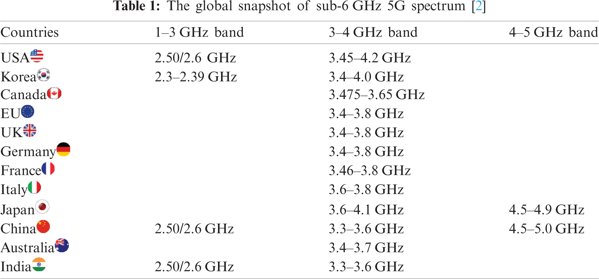
The race to 5th-generation (5G) communication has brought a significant paradigm shift in terms of diverse frequency allocation with massive bandwidths, low-latency, device densities, and very high number of transceiver antennas. The 3GPP (3rd Generation Partnership Project) has recently developed the 5G new radio (NR) air interface of 5G networks. This new radio access technology has very low latency (<1 ms) and high data rate, 100 times faster than 4G-LTE. The 5G NR is subdivided into frequency range 1 (FR1) and frequency range 2 (FR2). The FR1 uses frequency bands in sub-6 GHz, while the FR2 uses frequency bands in the millimeter (mm) wave range [1]. The frequency bands below 3 GHz within the sub-6 GHz band are traditionally used by 3G/4G mobile communication system, while the bands from 5 to 6 GHz are used for the WLAN 5-GHz band (5150–5825 MHz). The potential new spectrum for 5G NR (FR1) bands includes n77 (3300–4200 MHz), n78 (3300–3800 MHz), and n79 (4400–5000 MHz). This new spectrum has been allocated by different countries for communication in 5G sub-6 GHz as shown in Tab. 1 [2].
The division of electromagnetic spectrum into different sub-bands has increased the demand of antennas operating in these bands. The electromagnetic waves in these bands suffer from more severe free-space loss and blockage, which substantially degrades the signal-to-interference-plus noise ratio (SINR) [3]. To cope with this shortcoming, high-gain antennas with a directional beam can be deployed (possibly at both transmitting and receiving ends), which greatly enhances the SINR, mitigates the Doppler effect, and improves the data security.
The booming development of various wireless communication systems have posed a great challenge to have innovative antenna technologies like diversity antennas, reconfigurable antennas, metamaterial-based antennas, and antennas for software defined radio. Recently, circularly polarized (CP) microstrip antennas have got a great attention and it has been part of different wireless communication systems, such as for satellite communication, 3G/4G communication, GPS (Global Positioning System), RFID (Radio-frequency identification) tag, and RFID readers owing to its resilience to multipath interference and polarization mismatch [4–6]. On the other hand, these CP radiators have inherently low gain, narrow impedance bandwidth, and axial ratio bandwidth (ARBW). To upgrade these characteristics, researchers have adopted many techniques to improve these bandwidths like using stacked patches with truncated opposite corners [7,8] and using L-shape probe with impedance matching networks [9,10]. Nevertheless, these techniques give bulky size to antenna which is no longer low profile due to additional impedance Matching networks and antenna height.
Therefore, researchers came up with the new idea of using high impedance surfaces (HISs) or artificial magnetic conductors (AMCs), such as electromagnetic band-gap (EBG) structures [11,12], photonic band-gap structures [13], and artificial grounds to overcome these issues. These AMC structures include periodic metallic patches printed on grounded dielectric substrate and connected to the ground through shorting pins. The beneficial characteristics of these structures is having high impedance and in-phase reflection when excited by transverse electric and magnetic (TEM) radiations. To ease the fabrication process and complexity, AMCs are used in the absence of shorting pins and hence, it does not offer band-gap characteristics [14,15]. Such structures are not only used as a ground plane for shielding the antenna's electronics beneath it and to redirect the radiations to the upper side of antenna, but also improve the antenna performance characteristics. The usage of these surfaces in antenna design has been widely reported in literature [16–29]. In [16], a circularly polarized microstrip patch antenna based on artificial ground structure having rectangular unit cells is presented with a wide impedance bandwidth of 48.6% and ARBW of 20.4%. Similarly, [17] reported an AMC reflector backed aperture antenna with an impedance and axial ratio bandwidths of 36.2% and 33.2%, respectively. An AMC based circularly polarized cross dipole antenna was studied in [18]. The antenna operates in the bandwidth of 1.19–2.37 GHz with the maximum gain of 6 dBic. A CPW-fed slot antenna backed by FSS (frequency selective surface) is reported for radar and satellite applications [19]. This antenna has an impedance bandwidth of 63.22% (2.65–5.10 GHz) while ARBW is 31.14% (3.66–5.01 GHz) with the maximum gain of 4.87 dBic. However, many of the antennas reported in the literature have shown either high gain or wide bandwidths (impedance and AR) but not both [20–29].
CPW feed structure can be found widely in literature for its usage in many wideband circularly polarized antennas to improve ARBW [30–32]. This structure has many advantages like single metal layer, feed and radiation units in the same plane, and ease of integration with an active device. In [30], it was shown that two unequal and inverted L structures are introduced at the two corners of a CPW feeding slot, and two orthogonal resonant modes are produced to make circularly polarized waves, and the ARBW is 32.2%. The antenna in [31], uses systematically modified coplanar ground planes to achieve a maximum ARBW of 68.5%. However, these circularly polarized antennas based on coplanar waveguide (CPW) feed structure have maximum gain of 4 dBic.
There is very little research on circularly polarized antennas with an AMC surface for 5G sub-6 GHz communications due to the latest allocation of frequency bands (n77, n78, n78) under 5G NR. The inspiration behind the design of this antenna is to have a CPW-fed circularly polarized antenna based on AMC which could cover n77/n78/n79 bands of 5G NR communication system. In this paper, a wideband circularly polarized monopole antenna backed by AMC is designed with high antenna gain for unidirectional radiation. The organization of this paper is such that, the Section 2 discusses the configuration of the proposed antenna with its geometry, CP mechanism, parametric study, and AMC characterization in detail. The Section 3 briefly discusses performance of antenna over different reflectors. The Section 4 shows the proposed antenna performance with its simulated and measured results. Finally, the conclusion is drawn in Section 5.
The schematic diagram of proposed wideband circularly polarized monopole antenna is depicted in Fig. 1. The geometry of antenna includes two asymmetrical ground planes excited by a 50-ohm monopole with the length lm = 13.5 mm and a coplanar gap x = 0.7 mm. The two coplanar ground planes are placed parallel to the opposite sides of feedline. This geometry of metallic patches (microstrip line and coplanar ground planes) having a uniform standard thickness of 0.035 mm, is printed on a low dielectric substrate (Rogers 4003C,
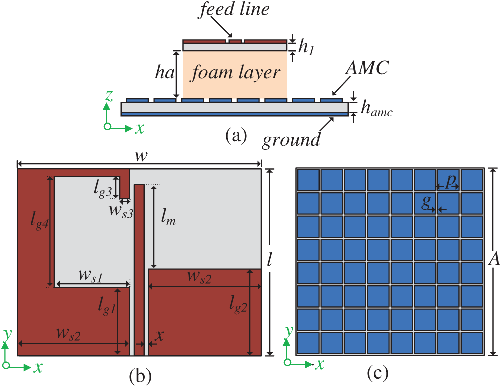
Figure 1: The geometry of the proposed antenna: (a) side view of the proposed antenna; (b) top view of the monopole antenna; and (c) top view of the AMC
This monopole antenna structure is backed by an AMC surface which is acting as a reflector surface and it is placed at a distance of “ha” from the antenna. The overall dimensions of monopole antenna backed by AMC reflector is 1.20λ0 × 1.20λ0 × 0.21λ0. The proposed antenna is implemented and simulated using CST Microwave Simulation (CST MS) tool. The final optimized parameters of antenna are listed in Tab. 2.
Firstly, it is necessary to discuss how the CP radiations can be generated before going to analyze the CP mechanism in the present case of monopole antenna. For the CP radiation, current distribution forming a loop gives CP [33], which is the first scenario of CP radiations on which this monopole antenna radiates. To understand this phenomenon, the surface current distribution at 3.5 GHz on exciting the antenna is shown in Fig. 2a. The CP mode is generated by left side coplanar ground plane where a rectangular etched slot makes a quasi-loop. This path allows the surface current to flow, and it is highlighted using arrows to indicate the formation of CP radiation. The counterclockwise direction of current flow can be observed in Fig. 2a. Hence, it generates right hand circular polarization (RHCP) in +z direction which is one sense of CP mode.
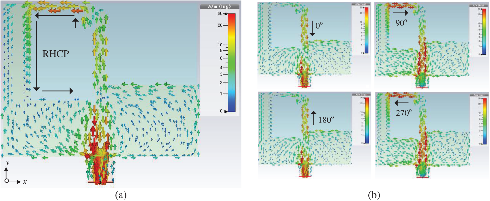
Figure 2: CP mechanism of monopole antenna with surface current distribution: (a) at 3.5 GHz; (b) at 4 GHz
The second scenario can be visualized by Fig. 2b where the position of strong vertical and horizontal components of electrical field (EHor, EVer) are shown for different phases at 4 GHz. In general, CP radiations are generated by EHor, EVer field having equal amplitudes with 90° phase difference [34]. The surface current induced in feedline of the proposed antenna produces strong vertical field component and the surface current induced on asymmetric coplanar ground plane on right side of feedline produces strong horizontal field component. These vertical and horizontal sections of antenna are carefully optimized to achieve 90° phase difference which ultimately generates the CP radiation.
This section studies the performance effect on monopole antenna by analyzing the length of monopole (lm) and coplanar gap (x). The optimized values for these two important parameters are playing key role for impedance matching and CP behavior of monopole antenna.
Fig. 3 depicts the |S11| and AR plots corresponding to the variations in lm while keeping constant all other parameters. It can be seen from Fig. 3a that the |S11| is sensitive to the change in lm especially in the upper band and it deteriorates in the lower band. On the other hand, the upper band in AR plot shown in Fig. 3b is strongly dependent on lm while lower band is slightly affected by it. So, we can adjust lm to get good impedance matching and 3-dB ARBW while considering the desired lower cut off frequency for our monopole antenna.
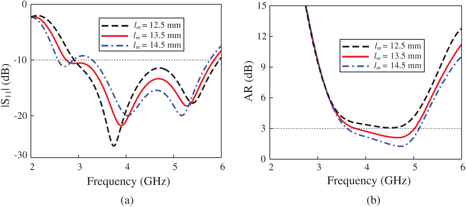
Figure 3: Simulated monopole antenna performance with different lm: (a) |S11|; (b) AR
It is well known that one of the components of travelling E-field along vertical direction in strip line feed causes to generate CP radiation. Therefore, the changing the length of lm can affect the CP radiation. Finally, the optimized value for lm is chosen to be 27.5 mm. The outcomes of change in coplanar gap between feedline and ground planes are illustrated in Fig. 4. It could be observed that the change in x causes major shift in upper band of |S11| and AR plots as shown in Figs. 4a and 4b respectively. This is due to the change in relative position of coplanar ground planes in x-direction. Hence, it effects the coupling capacitance between feedline and coplanar ground planes. The optimized value to cater this effect is 0.7 mm and it provides the better |S11| and 3-dB ARBW.

Figure 4: Simulated monopole antenna performance with different x: (a) |S11|; (b) AR
2.4 AMC Design and Its Characterization
In this study, the AMC having periodic square unit cells (8 × 8) is used as a metallic reflector to redirect the radiations in a boresight of monopole antenna. The proposed structure contains periodical lattice having a periodicity (p = 10.8 mm) on a grounded substrate as shown in the Fig. 1c. This AMC is designed without shorting pins between patches and the ground plane. It uses a low-cost FR-4 substrate with a permittivity (

Figure 5: Characteristics of AMC unit cell: (a) AMC unit cell; (b) AMC unit cell side view; (c) circuit diagram for unit cell; (d) AMC unit cell simulation setup; and (e) flowchart for the optimization of unit cell through GA
This unit cell model given in the Fig. 5d is designed and simulated in CST MS tool by applying unit cell boundary conditions and floquet port excitation. The reflection phase diagram of AMC is shown in Fig. 6. The beneficial characteristic of this AMC is to give zero reflection phase at a fixed frequency of around 3.9 GHz and the useable bandwidth is between 2.1 to 4.8 GHz which is in general within the range of ±90 degree on either side of the central frequency. AMC acts as a perfect electric conductor (PEC) in the remaining band. Therefore, the optimization techniques can be used to get the desired working band.

Figure 6: Reflection phase diagram for AMC unit cell
We have used build in genetic algorithm (GA) of CST MWS tool to optimize the unit cell parameters. CST uses built in MATLAB control functions to get the optimum dimensions for the unit cell. It is well known that these optimizers based on GA are robust and use the concepts of evolution [35]. A flowchart from [36] to visualize that how the proposed optimization algorithm works is shown in Fig. 5e. The input variables and its ranges have been defined such as the AMC patch size (wamc) and gap (g) are given the range from 8 mm to 14 mm and from 0.5 mm to 1.2 mm, respectively. The height and relative permittivity of the AMC have been kept constant. The fitness function for the desired objective is defined as shown in the following Eq. (1) [37].
where
The antennas which are backed by AMC give extra resonances due to travelling surface waves on AMC structure. In [38], a cavity model is employed to predict the surface wave resonances of an antenna backed by AMC ground plane without shorting pins. The finite sized AMC structure acts as a parallel waveguide resonator and hence it increases AR bandwidth due to additional resonances. The concept of additional resonances is widely used in past research [39–42]. The surface wave resonances depend upon the dimensions of AMC and the following Eq. (2) shows this relation.
In above equation,
3 Analysis of Antenna in Free Space, Over PEC, and AMC Ground Planes
This section of paper discusses the performance analysis of monopole antenna in free space and when it is backed by finite-size PEC and AMC ground planes.
The monopole antenna alone on free space will be considered as reference model for the performance analysis. It can be used as bidirectional as well directional antenna. The bi-directional characteristics of this antenna are illustrated by radiation patterns (H-plane) in Fig. 7 at 4 and 4.3 GHz. The antenna gives RHCP radiation in the +z-direction and LHCP in the -z-direction. There is slight tilt in radiation pattern in each direction from the broadside direction due to the asymmetrical and uneven current distribution on the ground planes. The operating AR bandwidth is from 3.8 to 5 GHz as shown in the Fig. 8a. The maximum gain of monopole antenna without AMC reflector is 3.35 dBic as shown in Fig. 8b. The monopole antenna alone finds its application in n79 (4400 MHz to 5000 MHz) band of 5G sub-6 GHz.
The monopole antenna backed by finite PEC ground plan is simulated instead of AMC ground plane. According to image theory that any radiator placed in proximity and parallel to PEC will have a negative image thus cancel each other. This happens when the radiated field from the image current cancels the radiated field emitted by antenna current itself. It causes sudden increase in the stored electromagnetic energy of the antenna near-field due to the presence of PEC ground plane [43]. Subsequently, this will give rise to high Q factor and eventually decrease the antenna bandwidth and gain. A solution to this problem is to have the PEC reflector at a minimum distance of 0.25λ0 from the radiating antenna which in this case is 20 mm at a frequency of 3.7 GHz. It will give a good impedance matching and hence, wide axial ratio and high gain for the antenna as shown in Figs. 8a and 8b, respectively.

Figure 7: Radiation patterns of the antenna in yz-plane at different frequencies

Figure 8: (a) AR comparison of monopole alone, with PEC, and with AMC; (b) gain comparison of antenna alone, with PEC, and with AMC
The bidirectional monopole antenna (discussed in Subsection 3.1) is converted into unidirectional by using the AMC surface which gives a 0° reflection phase unlike the PEC which causes a phase reversal. The properties of this surface are discussed in subsection of Section 2. By keeping the radiator at a foam height of ha = 14 mm (0.18λ0) above the AMC surface, the proposed antenna is investigated for the desired performance results. The monopole antenna in the presence of AMC gives RHCP radiations in the +z direction with high gain of around 8.7 dBic which is nearly 2.6 times of the gain offered by the monopole antenna alone. AR bandwidth is also increased in this case due to additional resonances generated by AMC surface. From Fig. 8a, it is shown that monopole antenna backed by AMC has greatest AR bandwidth as compared to the other cases. From the reflection phase diagram, we can see that reflection phase shifts to 180° degree at frequency around 5.2 GHz. This is where the destructive interference phenomenon occurs which makes the gain of antenna 0 dBic and even below it as shown in Fig. 8b. Therefore, the useable AR bandwidth of antenna under AMC operation is from 3 to 5.09 GHz. The gain of antenna starts to decline after 4.5 GHz.
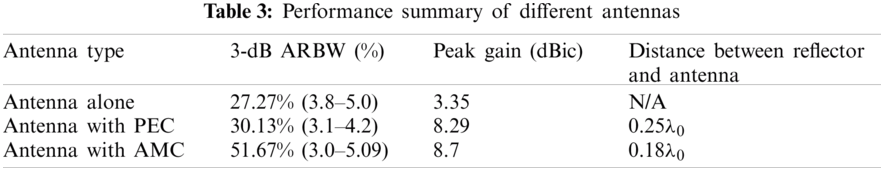
The limitations of antenna ARBW and gain when it radiates in free space, the drawback of PEC as a ground plane and the proposed AMC structure to enhance performance of monopole antenna all are graphically illustrated and compared its results in Tab. 3.
The prototype of the proposed AMC based wideband CP monopole antenna is fabricated and measured to validate the proposed design. Fig. 9a shows the antenna assembled parts and prospective view of the prototype. A carefully foam layer with the desired thickness is used between antenna and AMC reflector to realize the air gap. The setup for antenna far field measurements is shown in the photographs in Fig. 9b.
4.1 S-Parameters and Axial Ratio
The measured and simulated reflection coefficient |S11| is shown in Fig. 10a. Network analyzer (Rohde and Schwarz ZVA 40) in open-air condition is used to measure the |S11| parameter. The measured graphs indicate that proposed antenna has a wide impedance bandwidth of up to 63.22% from 2.91 to 5.6 GHz. The simulated and measured axial ratio of the proposed antenna is shown in Fig. 10b. The measured results show that proposed antenna has a wide 3-dB AR bandwidth of approximately 51.67% from 3 to 5.09 GHz.
To investigate the number of resonances, we calculate the modal significance and characteristic angle of characteristics modes for the proposed antenna using free source CMA (characteristic mode analysis) [44,45] as shown in Fig. 11. It can be seen that the modal significance is greater than 0.9 at two frequencies, which means that at those frequencies the resonate modes can be excited. The frequencies at the peak of mode 1 and 2 are close to the two resonances of antenna which can be visualized from the |S11| response of the antenna. These two frequencies are 3.8 and 4.7 GHz. The model significance of mode 1 and mode 2 becomes equal at 4.2 GHz. Correspondingly, as shown in Fig. 11b, the phase difference of the characteristic angles between mode 1 and 2 is approximate 90° at this frequency (4.2 GHz) which is the necessary condition for CP radiation.

Figure 9: Photographs of the: (a) fabricated antenna parts; (b) far-field measurement setup

Figure 10: (a) S-parameter |S11| of the proposed monopole antenna backed by AMC reflector; (b) axial ratio of the proposed monopole antenna backed by AMC reflector
4.2 Broadside Gain and Efficiency
The simulated and measured broadside gain of the monopole antenna with AMC reflector is shown in Fig. 12a. The gain for the proposed antenna is around 8.7 dBic. It has a stable gain above 8 dBic for 5G sub-6 GHz bands (n77/n78) of 5G technology. The antenna radiation efficiency and total efficiency of the antenna is illustrated in Fig. 12b. The antenna efficiency is measured in an anechoic chamber by feeding some power to the antenna feed pads and measuring the strength of the radiated electromagnetic field in the surrounding space. The proposed antenna has an average in-band radiation efficiency of 93% with the peak value goes up to 97%. Furthermore, the total average efficiency of the antenna is approximately 91%. These results show that the antenna is suitable for 5G sub-6 GHz band since, its ARBW and stable gain is limited from 3 to 5.09 GHz. However, the antenna has |S11| bandwidth from 2.91 to 5.6 GHz but the gain decreases to 0 dBic after 5 GHz.

Figure 11: (a) Model significance of the proposed antenna; (b) characteristic angle of the proposed antenna
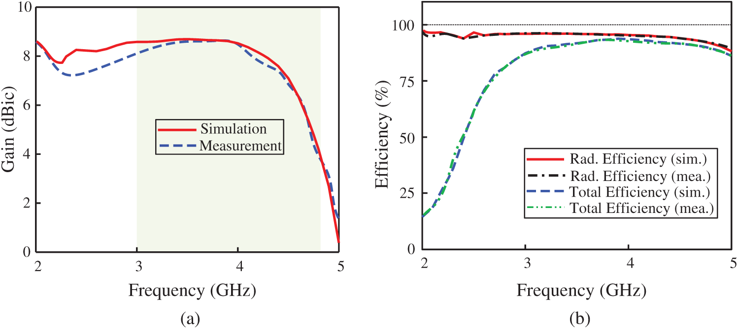
Figure 12: (a) Broadside gain of the proposed monopole antenna backed by AMC surface; (b) antenna radiation efficiency and total efficiency of the proposed monopole antenna backed by AMC surface
The characteristics of radiation pattern of the antenna is investigated with the integrated AMC surface behind the antenna, which redirects all the electromagnetic energy to the broadside direction. The simulated and measured radiation patterns of proposed antenna are analyzed in both xoz- and yoz-principal planes at three different frequencies 3.3, 3.7, and 4.1 GHz. The antenna is oriented with respect to the coordinate system given in Fig. 1. Therefore, the antenna has RHCP sense of polarization in the +z-direction whereas the LHCP in the -z-direction is negligible as compared to the RHCP. The polar plot results shown in Fig. 13 depicts stable and symmetrical radiation characteristics in the +z-direction.

Figure 13: Radiation patterns of the proposed monopole antenna backed by AMC surface at different frequencies: (a) 3.3 GHz; (b) 3.7 GHz; and (c) 4.1 GHz
4.4 Performance Comparison of the Proposed Antenna with Similar AMC Based CP Antennas
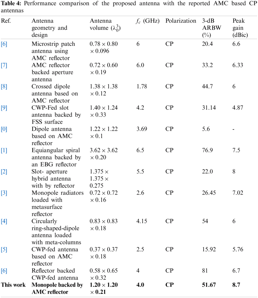
Tab. 4 shows the comparison of the proposed antenna with the existing similar AMC based circular polarized antennas. The comparison is made with respect to different performance metrics including antenna design geometry, overall antenna size, gain of the antenna, polarization, and AR bandwidths. It can be observed that the proposed antenna has shown outstanding performance including wider |S11| bandwidth, AR bandwidth, and the highest gain. Many interesting designs of AMC based CP antennas were reported [16–26]. However, they demonstrated either high gain or wide bandwidths (|S11| and AR) but not both.
The equiangular spiral antenna [21] has second largest |S11| bandwidth and ARBW as compared to the proposed antenna but its overall volume is twice larger than the proposed antenna. The antenna [26] has highest AR bandwidth but it has higher antenna profile and less gain than our work. The highest gain of 8.7 dBic, wide bandwidths (|S11| and AR), and small volume of proposed antenna make it better candidate for the wide coverage, wideband, stable gain, and stable radiation pattern in the 5G NR bands.
An AMC-based CP wideband circularly polarized monopole antenna with unidirectional radiation characteristics has been studied and presented for 5G sub-6 GHz band. A CPW feeding with asymmetrical ground planes is used for generating the CP radiation. The rectangular etched ground plane on the left side of microstrip line makes a loop path for the current flow which generates one sense of CP radiation. The additional CP is produced by exciting two orthogonal modes which are generated by the vertical/horizontal current flowing on the feedline and the shortened ground plane. An AMC surface is used as a back reflector to achieve wide ARBW, high gain and unidirectional CP radiation. The proposed antenna is studied under three performance scenarios i.e., antenna in free space, antenna over PEC ground plane, and antenna over AMC ground plane. It has been discussed that antenna with AMC gives the best overall results including wide AR bandwidth, high gain, and unidirectional CP radiation. The distance between monopole antenna and back reflector is minimized from 0.25λ0 to 0.18λ0 by integrating AMC surface as compared to the conventional metallic reflector.
Acknowledgement: The author acknowledges the research environment provided by OIP Lab, Chungbuk National University, Korea.
Funding Statement: This work was supported in parts by Institute for Information and Communication Technology Promotion (IITP) (A study on Public Health and Safety in a Complex EMF Environment), under Grant 2019-0-00102, and in part by Radio Research Agency (RRA) (Development of Rapid Antenna Measurement Technique for Antennas with New Radio Technology).
Conflicts of Interest: The authors declare that they have no conflicts of interest to report regarding the present study.
1. H.-D. Chen, Y.-C. Tsai and C. Kuo, “Broadband 8-antenna array design for sub-6 GHz 5G NR bands metal-frame smartphone applications,” IEEE Antennas and Wireless Propagation. Letters, vol. 19, no. 7, pp. 1078–1082, 2020. [Google Scholar]
2. Spectrum for 4G and 5G, Qualcomm Technologies Inc. 2020. [Online]. Available: https://www.qualcomm.com/media/documents/files/spectrum-for-4g-and-5g.pdf (Accessed Dec. 31, 2020). [Google Scholar]
3. F. Qamar, M. U. A. Siddiqui, M. Hindia, R. Hassan and Q. N. Nguyen, “Issues, challenges, and research trends in spectrum management: A comprehensive overview and new vision for designing 6G networks,” Electronics, vol. 9, no. 9, pp. 1–39, 2020. [Google Scholar]
4. Z. N. Chen and X. Qing, “A compact circularly polarized cross-shaped slotted microstrip antenna,” IEEE Transactions on Antennas and Propagation, vol. 60, no. 3, pp. 1584–1588, 2011. [Google Scholar]
5. K. M. Mak, H. W. Lai, K. M. Luk and C. H. Chan, “Circularly polarized patch antenna for future 5G mobile phones,” IEEE Access, vol. 2, pp. 1521–1529, 2014. [Google Scholar]
6. M. Samsuzzaman, M. T. Islam and M. J. Singh, “A compact printed monopole antenna with wideband circular polarization,” IEEE Access, vol. 6, pp. 54713–54725, 2018. [Google Scholar]
7. K. L. Chung and A. S. Mohan, “A systematic design method to obtain broadband characteristics for singly-fed electromagnetically coupled patch antennas for circular polarization,” IEEE Transactions on Antennas and Propagation, vol. 51, no. 12, pp. 3239–3248, 2003. [Google Scholar]
8. S. Kim and W. Yang, “Single feed wideband circular polarised patch antenna,” Electronics Letters, vol. 43, no. 13, pp. 703–704, 2007. [Google Scholar]
9. K. Lau and K. Luk, “A novel wide-band circularly polarized patch antenna based on L-probe and aperture-coupling techniques,” IEEE Transactions on Antennas and Propagation, vol. 53, no. 1, pp. 577–582, 2005. [Google Scholar]
10. K.-L. Lau and K.-M. Luk, “A wide-band circularly polarized L-probe coupled patch antenna for dual-band operation,” IEEE Transactions on Antennas and Propagation, vol. 53, no. 8, pp. 2636–2644, 2005. [Google Scholar]
11. D. Sievenpiper, L. Zhang, R. F. Broas, N. G. Alexopolous and E. Yablonovitch, “High-impedance electromagnetic surfaces with a forbidden frequency band,” IEEE Transactions on Microwave Theory and Techniques, vol. 47, no. 11, pp. 2059–2074, 1999. [Google Scholar]
12. A. Abbas, N. Hussain, J. Lee, S. G. Park and N. Kim, “Triple rectangular notch UWB antenna using EBG and SRR,” IEEE Access, vol. 9, pp. 2508–2515, 2020. [Google Scholar]
13. R. Coccioli, F.-R. Yang, K.-P. Ma and T. Itoh, “Aperture-coupled patch antenna on UC-pBG substrate,” IEEE Transactions on Microwave Theory and Techniques, vol. 47, no. 11, pp. 2123–2130, 1999. [Google Scholar]
14. Y. Zhang, J. Von Hagen, M. Younis, C. Fischer and W. Wiesbeck, “Planar artificial magnetic conductors and patch antennas,” IEEE Transactions on Antennas and Propagation, vol. 51, no. 10, pp. 2704–2712, 2003. [Google Scholar]
15. Q. Chen and H. Zhang, “High-gain circularly polarized fabry–Pérot patch array antenna with wideband low-radar-cross-section property,” IEEE Access, vol. 7, pp. 8885–8889, 2019. [Google Scholar]
16. T. Nakamura and T. Fukusako, “Broadband design of circularly polarized microstrip patch antenna using artificial ground structure with rectangular unit cells,” IEEE Transactions on Antennas and Propagation, vol. 59, no. 6, pp. 2103–2110, 2011. [Google Scholar]
17. K. Agarwal and A. Alphones, “Wideband circularly polarized AMC reflector backed aperture antenna,” IEEE Transactions on Antennas and Propagation, vol. 61, no. 3, pp. 1456–1461, 2012. [Google Scholar]
18. D. Feng, H. Zhai, L. Xi, S. Yang, K. Zhang, D. Yang et al., “A broadband low-profile circular-polarized antenna on an AMC reflector,” IEEE Antennas and Wireless Propagation Letters, vol. 16, pp. 2840–2843, 2017. [Google Scholar]
19. P. K. T. Rajanna, K. Rudramuni and K. Kandasamy, “A wideband circularly polarized slot antenna backed by a frequency selective surface,” Journal of Electromagnetic Engineering and Science, vol. 19, no. 3, pp. 166–171, 2019. [Google Scholar]
20. F. Yang and Y. Rahmat-Samii, “A low profile single dipole antenna radiating circularly polarized waves,” IEEE Transactions on Antennas and Propagation, vol. 53, no. 9, pp. 3083–3086, 2005. [Google Scholar]
21. H. Nakano, K. Kikkawa, N. Kondo, Y. Iitsuka and J. Yamauchi, “Low-profile equiangular spiral antenna backed by an EBG reflector,” IEEE Transactions on Antennas and Propagation, vol. 57, no. 5, pp. 1309–1318, 2009. [Google Scholar]
22. Y. C. Lu, M. J. Yu and Y. C. Lin, “A single-FED slot-aperture hybrid antenna for broadband circular polarization operations,” Microwave and Optical Technology Letters, vol. 54, no. 2, pp. 412–415, 2012. [Google Scholar]
23. M. Ameen, O. Ahmad and R. Chaudhary, “Wideband circularly-polarised high-gain diversity antenna loaded with metasurface reflector for small satellite applications,” Electronics Letters, vol. 55, no. 15, pp. 829–831, 2019. [Google Scholar]
24. B. Feng, L. Li, K. L. Chung and Y. Li, “Wideband widebeam dual circularly-polarized magnetoelectric dipole antenna/Array with meta-columns loading for 5G and beyond,” IEEE Transactions on Antennas and Propagation, vol. 69, no. 1, pp. 219–228, 2020. [Google Scholar]
25. M. Ameen and R. Chaudhary, “Metamaterial-based wideband circularly polarised antenna with rotated V-shaped metasurface for small satellite applications,” Electronics Letters, vol. 55, no. 7, pp. 365–366, 2019. [Google Scholar]
26. U. Ullah, S. Koziel and I. B. Mabrouk, “A simple-topology compact broadband circularly polarized antenna with unidirectional radiation pattern,” IEEE Antennas and Wireless Propagation Letters, vol. 18, no. 12, pp. 2612–2616, 2019. [Google Scholar]
27. D. A. Sehrai, F. Muhammad, S. H. Kiani, Z. H. Abbas, M. Tufail et al., “Gain-enhanced metamaterial based antenna for 5g communication standards,” Computers, Materials & Continua, vol. 64, no. 3, pp. 1587–1599, 2020. [Google Scholar]
28. J. Khan, D. A. Sehrai, M. A. Khan, H. A. Khan, S. Ahmad et al., “Design and performance comparison of rotated y-shaped antenna using different metamaterial surfaces for 5G mobile devices,” Computers, Materials & Continua, vol. 60, no. 2, pp. 409–420, 2019. [Google Scholar]
29. S. Narayan, S. J. B., R. U. Nair and R. M. Jha, “Electromagnetic performance analysis of novel multi-band metamaterial fss for millimeter wave radome applications,” Computers, Materials & Continua, vol. 31, no. 1, pp. 1–16, 2012. [Google Scholar]
30. J. Pourahmadazar, C. Ghobadi, J. Nourinia, N. Felegari and H. Shirzad, “Broadband CPW-fed circularly polarized square slot antenna with inverted-l strips for UWB applications,” IEEE Antennas and Wireless Propagation Letters, vol. 10, pp. 369–372, 2011. [Google Scholar]
31. U. Ullah, I. B. Mabrouk, S. Koziel and M. Al-Hasan, “Implementation of spatial/Polarization diversity for improved-performance circularly polarized multiple-input-multiple-output ultra-wideband antenna,” IEEE Access, vol. 8, pp. 64112–64119, 2020. [Google Scholar]
32. R. Cao and S.-C. Yu, “Wideband compact CPW-fed circularly polarized antenna for universal UHF RFID reader,” IEEE Transactions on Antennas and Propagation, vol. 63, no. 9, pp. 4148–4151, 2015. [Google Scholar]
33. R.-L. Li, V. F. Fusco and H. Nakano, “Circularly polarized open-loop antenna,” IEEE Transactions on Antennas and Propagation, vol. 51, no. 9, pp. 2475–2477, 2003. [Google Scholar]
34. K. Ding, C. Gao, Y. Wu, D. Qu and B. Zhang, “A broadband circularly polarized printed monopole antenna with parasitic strips,” IEEE Antennas and Wireless Propagation Letters, vol. 16, pp. 2509–2512, 2017. [Google Scholar]
35. R. L. Haupt, “An introduction to genetic algorithms for electromagnetics,” IEEE Antennas and Propagation Magazine, vol. 37, no. 2, pp. 7–15, 1995. [Google Scholar]
36. L. Ali, Q. Li, T. A. Khan, J. Yi and X. Chen, “Wideband RCS reduction using coding diffusion metasurface,” Materials, vol. 12, no. 17, pp. 2708, 2019. [Google Scholar]
37. P. Kovacs, “Design and optimization of electromagnetic band gap structures,” Ph.D. dissertation, BRNO University of Technology, Czech Republic, 2010. [Google Scholar]
38. S. X. Ta and I. Park, “Artificial magnetic conductor-based circularly polarized crossed-dipole antennas: 2. AMC structure without grounding pins,” Radio Science, vol. 52, no. 5, pp. 642–652, 2017. [Google Scholar]
39. X. Li, J. Yang, Y. Feng, M. Yang and M. Huang, “Compact and broadband antenna based on a step-shaped metasurface,” Optics Express, vol. 25, no. 16, pp. 19023–19033, 2017. [Google Scholar]
40. F. Costa, O. Luukkonen, C. R. Simovski, A. Monorchio, S. A. Tretyakov et al., “TE surface wave resonances on high-impedance surface based antennas: Analysis and modeling,” IEEE Transactions on Antennas and Propagation, vol. 59, no. 10, pp. 3588–3596, 2011. [Google Scholar]
41. N. Hussain, M.-J. Jeong, A. Abbas, T.-J. Kim and N. Kim, “A metasurface-based low-profile wideband circularly polarized patch antenna for 5G millimeter-wave systems,” IEEE Access, vol. 8, pp. 22127–22135, 2020. [Google Scholar]
42. N. Hussain, M.-J. Jeong, A. Abbas and N. Kim, “Metasurface-based single-layer wideband circularly polarized MIMO antenna for 5G millimeter-wave systems,” IEEE Access, vol. 8, pp. 130293–130304, 2020. [Google Scholar]
43. H. Mosallaei and K. Sarabandi, “Antenna miniaturization and bandwidth enhancement using a reactive impedance substrate,” IEEE Transactions on Antennas and Propagation, vol. 52, no. 9, pp. 2403–2414, 2004. [Google Scholar]
44. C. Chunling, “Characteristic mode analysis and design of a slot-loaded low-profile wideband microstrip patch antenna,” Microwave Optical Technology Letters, vol. 62, no. 3, pp. 1374–1379, 2020. [Google Scholar]
45. X. Li, X. Xi, X. Yang, P. Chen and R. Wu, “Compact patch antenna enabled by a metasurface with stereo elements,” Optics Express, vol. 28, no. 26, pp. 38983–38992, 2020. [Google Scholar]
 | This work is licensed under a Creative Commons Attribution 4.0 International License, which permits unrestricted use, distribution, and reproduction in any medium, provided the original work is properly cited. |