DOI:10.32604/cmc.2022.018832
| Computers, Materials & Continua DOI:10.32604/cmc.2022.018832 | |
| Article |
Soil-Structure Interaction Effects on Dynamic Behaviour of Transmission Line Towers
1Faculté de Génie, Université de Sherbrooke, Québec, J1K 2R1, Canada
2Parsons, Abu Dhabi, P. O. 5498, UAE
*Corresponding Author: Abir Jendoubi. Email: abirjendoubi30@gmail.com
Received: 23 March 2021; Accepted: 30 April 2021
Abstract: As inferred from earthquake engineering literature, considering soil structure interaction (SSI) effects is important in evaluating the response of transmission line towers (TLT) to dynamic loads such as impulse loads. The proposed study investigates the dynamic effects of SSI on TLT behavior. Linear and non-linear models are studied. In the linear model, the soil is represented by complex impedances, dependent of dynamic frequency, determined from numerical simulations. The nonlinear model considers the soil non-linear behavior in its material constitutive law and foundation uplift in a non-linear time history analysis. The simplified structure behavior of a typical lattice transmission tower is assessed. The analysis of frequency and time domain are followed through varying soil stiffness and damping values. Three different shock durations are investigated. The soil-structure system with equivalent dynamic properties is determined. The behaviors achieved utilizing a rigid and a flexible base for the structures is compared to estimate the impact of taking SSI into account in the calculation. The current mainstream approach in structural engineering, emphasizing the importance of the SSI effect, is illustrated using an example where the SSI effect could be detrimental to the structure. Furthermore, the non-linear analysis results are analyzed to show the linear approach’s limitations in the event of grand deformations.
Keywords: Tower; shock loads; non-linear; dynamic soil-structure interaction
Transmission line (hereinafter referred to as TL) structures are commonly modeled with fixed base assumption neglecting the foundations flexibility. This assumption is debatable given the recognized importance of soil-structure interaction (hereinafter referred to as SSI) in different fields of structural engineering [1] such as earthquake engineering [2] and more widely under dynamic loadings. TL structures, which are built on overexposed area, are designed to support important dynamic loads suchlike those resulting from a conductor breakage [3]. Nonetheless, in most TL structural designs, static loads are computed and calibrated to be regarded comparable to the current dynamic load. Indicate that TL towers are generally assumed to be rigidly supported on infinitely stiff foundations. Nevertheless, because of new levels in the (re)design of (existing) structures thus far designed using conservative methods, this assumption was questioned by many practitioners [4] considering the significant importance of SSI recognized in other areas of structural engineering [5,6].
In the last decades, SSI effect has been largely studied, however, most research considered the foundation with an elastic linear behavior or, an equivalent-linear behavior at best. In previous work, the non-linear foundation behavior with hysteretic soil behavior and foundation-uplift was detailed [7]. Several studies have already investigated the soil flexibility effect on the structure response associated to foundation uplift [8–10] have modeled the underlying soil by spring-dashpot elements distributed without tension. Recently, [11] studied the uplift of foundation by creating a behavior law to explain the uplift mechanism with a single macro-element [12] investigated the non-linear SSI effect on steel braced structures by considering non-linearity in structure behavior only [13] analyzed the nonlinear behavior of stack-shaped towers under seismic SSI in 2012.
A detailed analysis of dynamic effects with non-linear SSI and foundation uplift is required to predict the transient reaction of TL towers to abrupt conductor rupture. Indeed, large deformations on the TL tower base may happens because of soil failure and foundation uplift in case of shock loads.
In this study, the major goal is to evaluate how linear and nonlinear SSI affect the dynamic response of rigid TL structures exposed to impulse loads. To study the influence of foundation flexibility, analyses are conducted out with finite element modeling. A parametric investigation is carried out as a preliminary step. A simplified latticed tower model is proposed with varying the foundation stiffness and damping. To determine the impact of impedances on the system dynamic properties, the soil structure system’s equivalent frequency and damping are determined. The impedance of the foundation is varied over a wide range in the parametric analysis to assess the parameter’s sensitivity. Coherent and granular soils were investigated for the simplified base tower to supplement these findings. To simulate the tower’s base, an iterative method was employed to establish the necessary impedances. To forecast the effect of SSI, a simple technique based on shock spectra is proposed.
The second stage investigates a real-world scenario of a low-voltage latticed tower with two types of elastic soil foundations. The nonlinear behavior of the soil as well as foundation uplift were then examined in order to assess their impact on the real-time reaction of the structure. The foundation displacements and resistance force are presented as results, are correspondingly compared to the linear response.
2.1 Simplified Structural Model
For simplification, the soil and the structure are modeled in this work by a commonly employed system [1] consisting of a basic structure based on a flexible foundation medium [4,14]. The ADINA solver is used in a parametric study to model the simplified structure, including the foundation (shown in Fig. 1a). The structure two parts are linked together at the top where all the applied loads are assumed to be exerted. As a result, the two sections are mostly subjected to axial forces, as they are in real tower with concentric tower legs and connectivity of paint of application of load. The members’ axial cross section A is 0.001 m2. The building stands 10 m tall and is made up of 2-node beam segments. The beams are completely weightless. The tower is made of linear elastic material with an elasticity modulus E of 2 × 10⁵ MPa. There are 40 beams that make up the primary members. A punctual mass of 395 kg is placed to the top of the structure. Thus, the structure frequency is 10 Hz which is a common value for latticed towers. Two footings support the building. The supports are 4 m apart. Impedances vertically and horizontally are applied at the structure’s two supports to model the foundation (Fig. 1b). The values of horizontal and vertical impedances are varied in a parametric analysis.
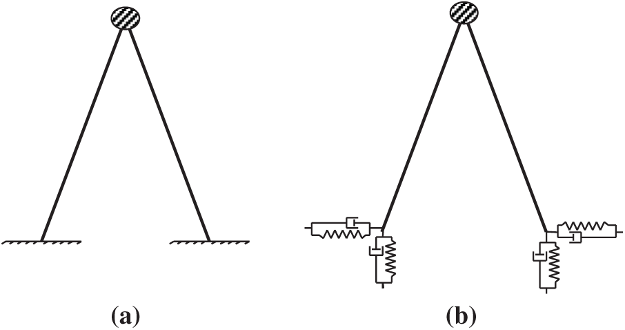
Figure 1: Simplified tower structure ((a): fixed base and (b): flexible base)
The calculation of the interface structure—foundation (Fig. 1b), named as the impedance functions (K = K + iω C) and defined as the ratio force-to-the consequent displacement, is a crucial step in the assessment of the linear effects of SSI. The stiffness of the soil-foundation system is represented by the real component K. The damping caused by energy dissipation in the soil, primarily by radiation, is represented by the imaginary component C. Analytical, semi-analytical, and boundary formulations, dynamic finite-element methods, and hybrid methods combining analytical and finite element approaches can all be used to determine impedances [15]. Reference [16] investigated the impedance functions that are used in SSI problems in depth. Reference [16] created different equations and charts for various types of footings based on numerically implemented analytical-integral-method for impedance determination. The soil is substituted in this article by dynamic frequency dependent and complex impedances derived from numerical simulations [17] using the FLAC (Itasca 2005) program, which are in good agreement with the solutions developed by [18]. A wide range of foundation stiffness K is investigated for the parametric investigation. Several foundation damping C values were studied. The determined impedances were used to create linear springs and dashpots in ADINA. The breadth of the foundation and its embedment are taken into account while determining the suitable impedance values. The foundations of transmission line pylons are designed to be more reliable, thus they aren’t supposed to deviate too much from elastic behavior [12].
Some TL structures are built to withstand shock loads caused by conductors that have broken. An impulse load is used in this analysis to represent the shock wave effect caused by the conductor breakage or ground wire. When one of these cables’ snaps, a series of dynamic tensile shock waves travels along it and partially reflects at the boundaries. This dynamic load is typically a series of impulse loads with time-varying amplitudes transmitted to the tower.
The impulse load known, in this study, as a semi-sinusoidal pulse-type excitation (Fig. 2), it is a punctual horizontal force applied at the structure’s top. There are two stages to a response to such an impulse. The first is the forced vibration phase, during which the cable/tower is subjected to an impulse load, and the second is the free vibration phase that follows. Generally, the load shock duration t is in the range 0.1 to 0.5 s. The shock load durations t, applied to the structure, are equal to 0.1, 0.25, and 0.5 s, as shown in Fig. 2 based on the impulse loads shock spectra given by [19]. The calculations are carried out for a total of 10 t. In the time domain, ADINA [20] is used to model the impulse-load dynamic effects.
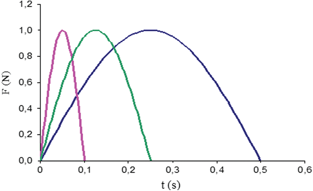
Figure 2: Different impulse loads (0.1 s—pink, 0.25 s—green and 0.5 s—blue)
Dynamic SSI depends on the structure and the underlying soil the properties. To better understand the behaviour of the soil-structure system, the equivalent stiffness and damping were determined analytically. Analytic and numerical (ADINA) results are compared.
3.1 Equivalent Stiffness and Frequency
The soil-structure system equivalent stiffness shown on Fig. 1b can be expressed using [19] and [21]. In the following equation the soil and the simplified structure were considered as springs in series. The equation was developed by applying a horizontal force on the top. The stiffness of the structure K0 was calculated based on matrix analysis and using the tilt angle of the structure members.
Kh and Kv are the foundation horizontal and vertical stiffness, a is foundations supports distance, h is the structure height, l is the length of each structure member and K0, the horizontal structure stiffness.
The system equivalent damping combines three terms: firstly, the structure's damping, secondly the foundation’s radiation damping as a result of soil medium wave propagation, and thirdly the material (or hysteretic damping) as a result of inter-granular friction in the soil. The structure is dampened by a Rayleigh damping of 2% in this investigation. To compute the equivalent damping of the soil-structure system, [22] presented the following approximation:
where,
The finite element code ADINA allow calculating the support reaction of the simplified structure in the time domain. A complete transient dynamic analysis was carried out. The Newmark’s average acceleration method is used, which uses Newton’s complete iterative process for energy convergence. The stiffness and damping of the foundation were varied in a parametric study. In the case of three impact durations, the ground impedance varies within a wide range of values. The horizontal and vertical stiffness of the soil varies from 5 × 10⁴ to 5 × 10⁸ kN/m. Soil damping varies between 104 and 5 × 10⁶ kN s/m. In total 120 computations were accomplished. The results are expressed as the time history of the structural support responses. The model maximum response in the case of elastic foundation is compared with that of rigid foundation under the TL structure.
The Figs. 3–5 indicate the ratio dimensionless-reactions R -to- the fixed-base reaction Rfix vs. t/T with different impedances values (T is the system period). The two foundations stiffness is varying in the range 5 × 10⁴ kN/m to 5 × 10⁶ kN/m which corresponds to a system frequency from 0.5 to 9.85 Hz. We infer that, unless there is a dynamic amplification, the response amplitude increases with soil stiffness. The magnitude of the responses tends to be similar at higher frequencies, around the structure fundamental frequency for the fixed base. The response is unaffected by the foundation damping, and the ratio of support reactions is around 1.
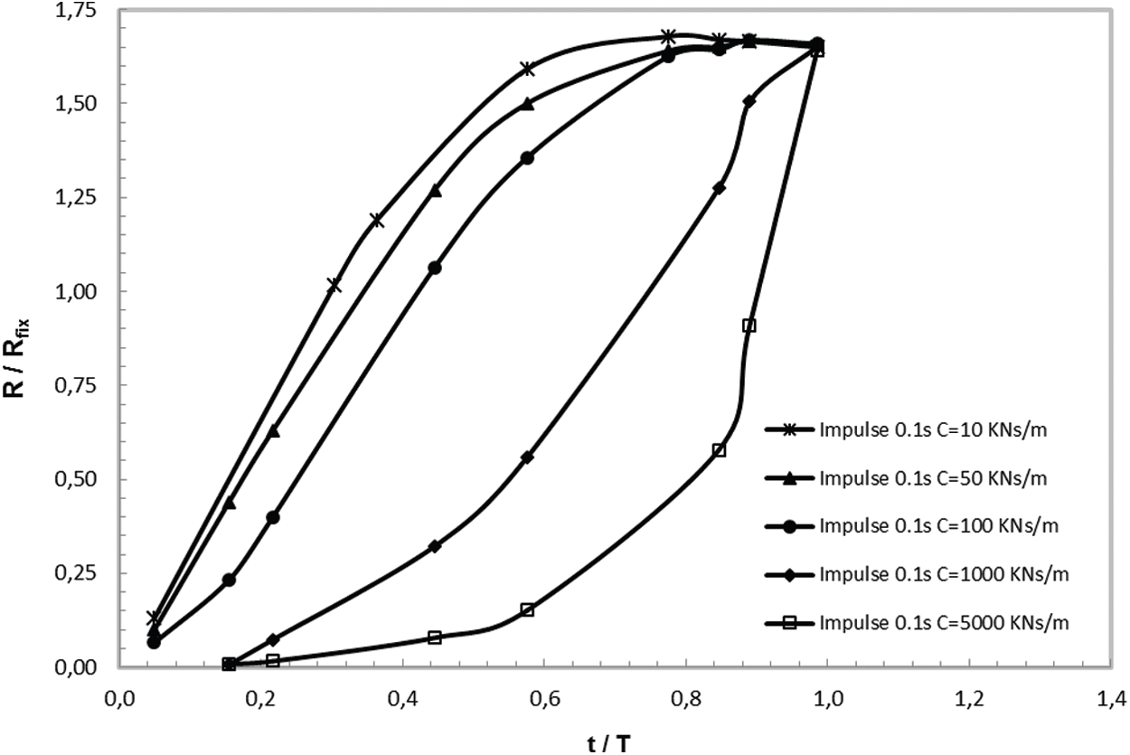
Figure 3: The supports reactions of the simplified structure in the of shock duration 0.1 s
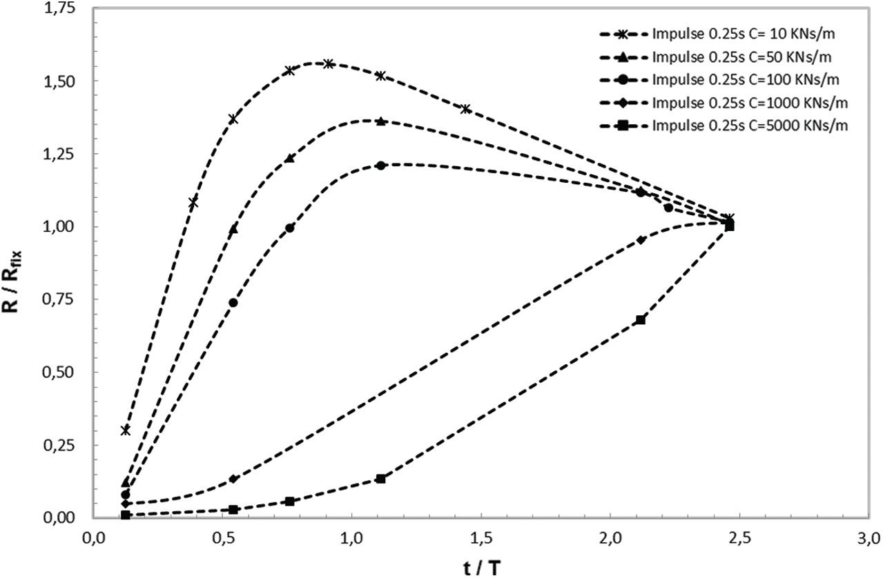
Figure 4: The supports reactions of the simplified structure in the of shock duration 0.25 s
There is a dynamic amplification for shock durations of 0.5 and 0.25 s, as can be seen. For t = 0.1 s, this phenomenon is not noticed because the length is so brief that damping has no major effect on the supports reaction. At lower frequencies, foundation damping has a greater influence. When the data for the three shock durations are compared, we find the maximum response at higher frequencies (5.8 Hz) correlates to td = 0.1 s. As a result, shocks with t equal to 0.5 s (3 Hz) cause the greatest response at lower frequencies. When the shock duration is equal to 0.25 s and the frequency is in the range 3 to 5.8 Hz, the maximum is reached. The shock spectra computed using LabVIEW code and presented in Fig. 6 are consistent with these results.
4.2 Comparison with the Fixed Based Structure
To enhance the parametric study, two types of soils, a coherent and a granular, were considered for which the impedances were determined and used for the simplified model supports. The coherent soil had a celerity Vs = 100 m/s, a Poisson’s ratio
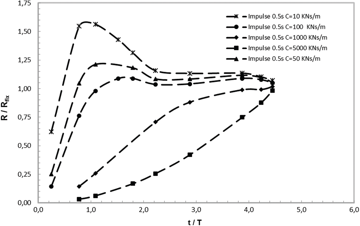
Figure 5: The supports reactions of the simplified structure in the of shock duration 0.5 s
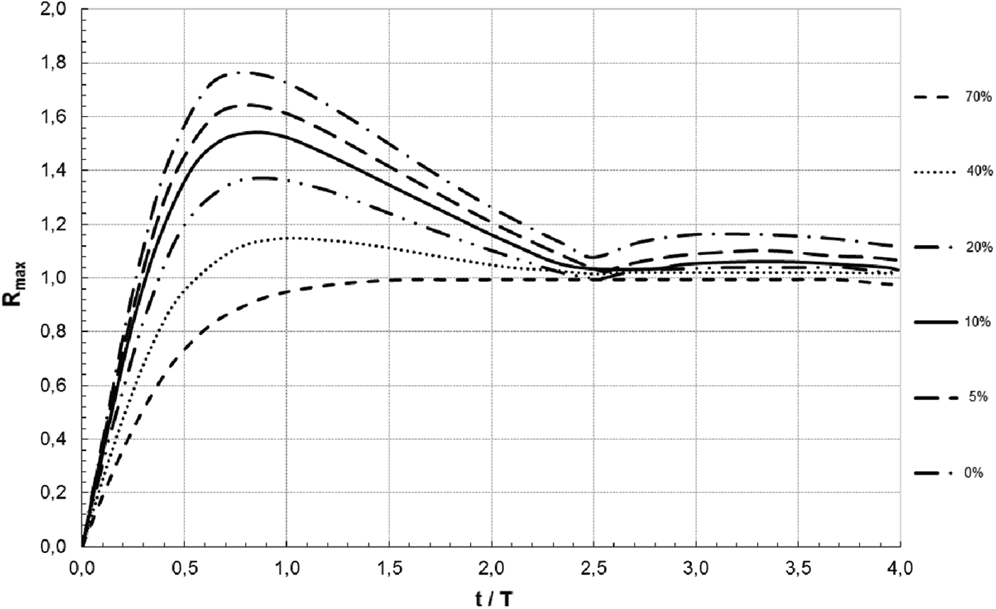
Figure 6: Shock spectra
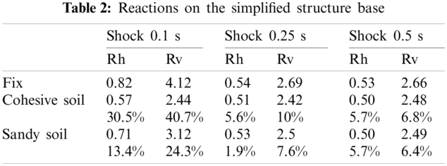
As shown on Tab. 2, when shock duration increases the maximum supports reactions values decrease. The support responses values for t = 0.25 s and t = 0.5 s are practically same if we consider the tower with fixed rigid base. When the shock duration is 0.1 s, the support’s reflexes are stronger. It is because the damping forces don’t have enough time to absorb a lot of energy from the structure. When the duration length is brief, the foundation stiffness has a greater impact than the foundation damping. In both granular and cohesive soils, including SSI decreases the values of reactions from 6% to 40% when compared to the results with fixed base.
The maximum response of the soil-structure reaction could be determined based on the shock spectra response given in Fig. 6 and the formulae defined by Eqs. (1), (4) and (5), and then the influence of SSI could be assessed. The shock spectrum response achieved with LabVIEW code under sinusoidal impulse loads is shown in Fig. 6. The maximum response generated in a damped simplified structure by a semi-sinus impulse load is plotted vs. of the ratio impulse duration-to-the structure’s natural period on this diagram. Each curve corresponds to an equivalent damping value. Tab. 3 indicates calculations of this method.
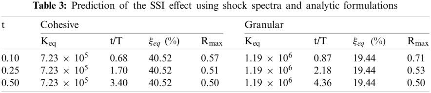
As indicated in this table, when the equivalent soil-structure system damping and period are known, from Fig. 6 we deduce the maximum response which confirm the results obtained on Figs. 3–5. The effect of SSI might be assessed by dividing the acquired maximum response value to the fixed base analytic one.
In this paragraph, a real latticed transmission tower is calculated. The impact of both linear and nonlinear SSI is measured. The foundation behavior is initially thought as elastic. A nonlinear analysis was also performed to account for the foundation's nonlinear behavior and the possibility of foundation uplift where deformations are larger.
A typical steel transmission tower [24] with real foundations shown in the Fig. 7 is considered to illustrate the SSI effect. The tower modeled with ADINA solver is 10 m height. It is supported by four footings and contains 144 beam elements and 130 truss elements. The tower has a mass of 3531 kg and a fundamental frequency of 10 Hz with a rigid base. Impulse loads of 0.1, 0.25, and 0.5 s are applied to the tower (Fig. 2).
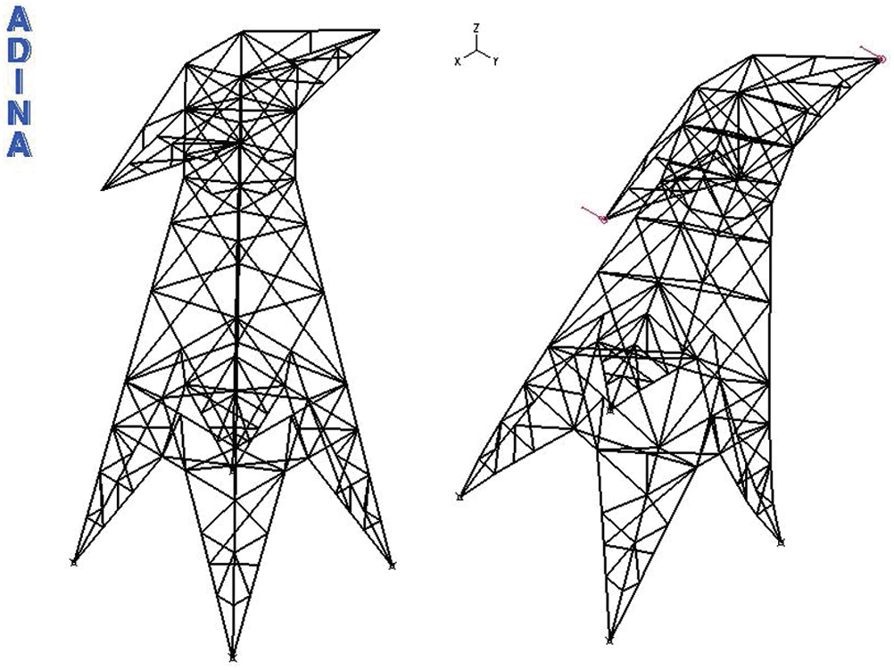
Figure 7: Latticed TLT model
5.2.1 Soil Impedances Applied on the Bases of the Real Tower
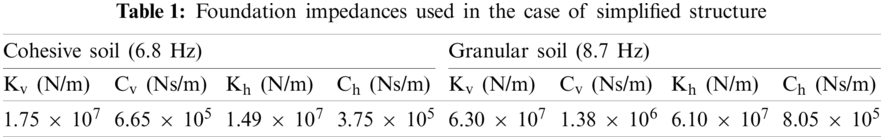
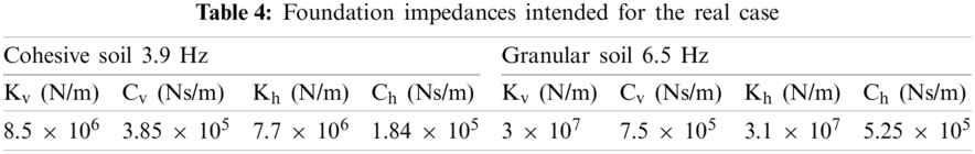
The base tower foundations are modeled using springs and dashpots in all three translation directions. 4 m between two supports is considered at the tower base. FLAC simulations [25] provided the impedance values used in the ADINA model. iterative calculation was required to predict the structure response fundamental effect, and by applying impedance and checking the value of the soil-structure system’s frequency each iteration until a system frequency equalize that one corresponding to the applied impedances was obtained. On Tab. 3, the values of soil stiffness and soil damping are shown. The ultimate system frequency for granular soil is 6.5 Hz, whereas the final system frequency for cohesive soil is 3.9 Hz. It indicates that impedances were determined at a frequency of 6.5 Hz, and in the case of cohesive medium, the corresponding frequency of the soil-structure system with those impedances is likewise 6.5 Hz. On Tab. 4, the soil stiffness and damping applied at each support are shown.
On the top of the tower model, an impulse load during 0.1 s is applied. The impedances of two soil types were applied on the supports of the tower: A coherent-soil having a Vs = 100 m/s, Poisson’s ratio 0.4 and a mass-density of 1600 kg/m3 and the second is a sandy media having a Vs = 200 m/s, Poisson’s ratio 0.33 and a mass-density of 2000 kg/m3.
Fig. 8 indicates the time histories in the cases of cohesive soil, granular soil, and with fixed base. The values of responses with a fixed base are higher than those with a flexible basis, as can be shown. When using granular media, the responses are more crucial than when using cohesive media. In cohesive soil, the effect of foundation damping is particularly critical.
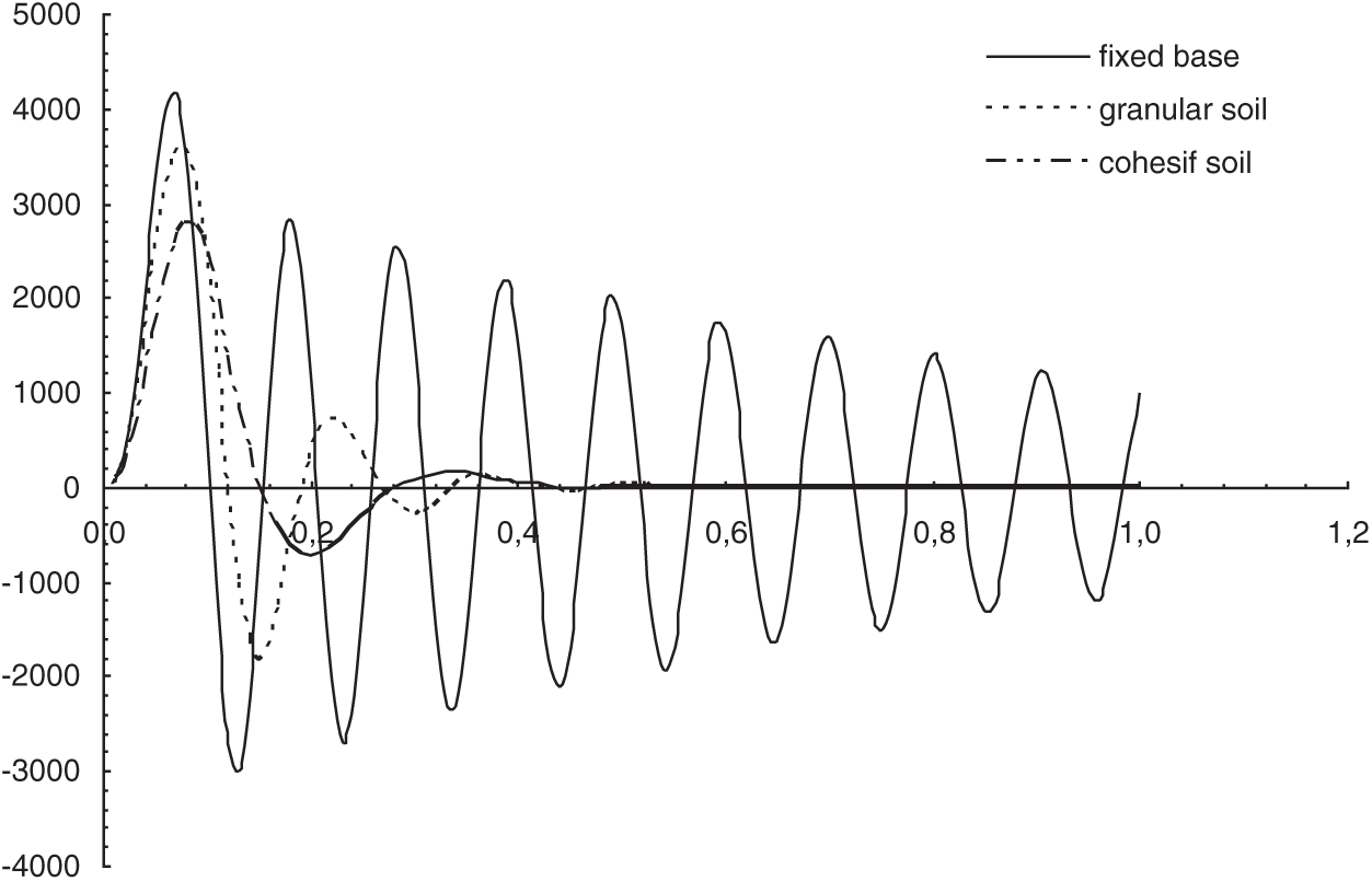
Figure 8: Time histories response examples on the latticed tower base
5.2.3 Comparison to the Fixed Base Response
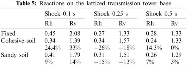
On Tab. 4, the values of the applied impedances on the real tower base are shown. Tab. 5 summarizes the reactions on the structure’s foundation. When considering a transmission tower for a fixed rigid base, the support response values for 0.25 and 0.5 s are nearly identical. When the shock duration is less than 0.1 s, the support's reflexes are stronger. The reactions values decrease when shock duration increase.
As there is no amplification of the response, including SSI decreases the values of reactions from 3% to 33% when compared to the findings with fixed base. The values of reactions with a flexible basis are bigger than the values of reactions with a fixed base in the case of a shock load with t equal to 0.25 s. The gap ranges from −13% to −26%. This is supported by Fig. 4. The positive impact of SSI is validated in this research, except when the soil damping is low, causing the dynamic response to be increased, as illustrated in Figs. 4 and 5. In this scenario, the SSI has a negative impact on the structure.
5.3.1 Modeling of the Nonlinear Foundation Behavior
In this section, nonlinear experimental vertical spring components were used to represent the non-linear behavior of the two raised foundations. Linear springs and dampers are used to model the two compacted foundations. The nonlinear elements are introduced in ADINA code as being experimental load-displacement curve [26]. The loading shown in Fig. 9 was applied directly to the foundation in the experimental test. Fig. 10 shows the load-displacement curve that was produced.
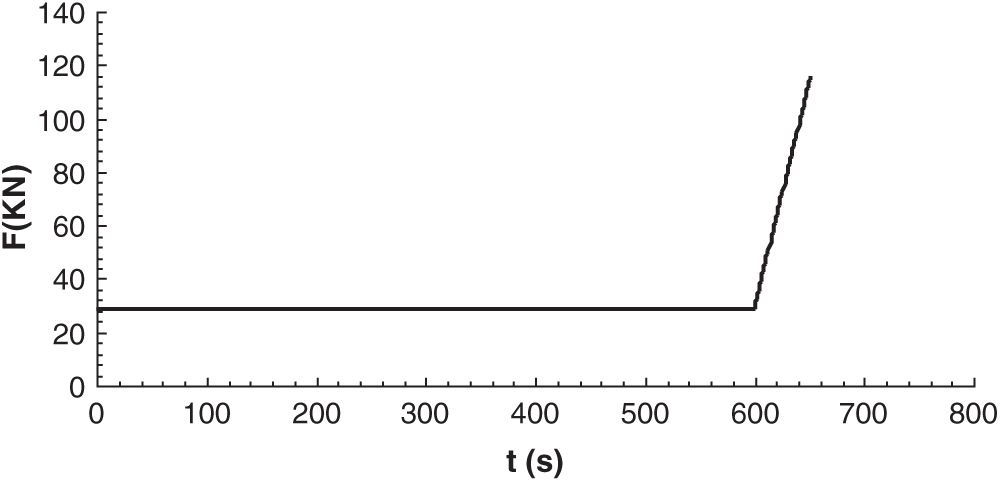
Figure 9: Foundation subjected to experimental load
The foundation’s material and geometric non-linearities are described by the force-displacement curve. Fig. 11 indicates the tested foundation geometry. The soil is granular with Poisson’s ratio = 0.33 and a mass density 1970 kg/m3. Considering the numerical simulation [17] and the tables and charts of [16], the values of impedances used in the numerical calculations for the two compressed supports are Kv = 1.04 × 10⁴ kN/m, Cv = 5 × 10² kN s/m. The horizontal impedances are so that Kh = 8.5 × 10³ kN/m and Ch = 3.2 × 10² kN s/m.
Vertical and horizontal displacements, as well as resistance forces, are reported as results. The results are compared to illustrate the influence of foundation non-linearities on support resistance and displacements, as well as to compare the behaviors of uplifted and compressed footings. A sinusoidal load (t = 0.5 s and Pmax) was applied on the top of the tower as indicated in Fig. 2.
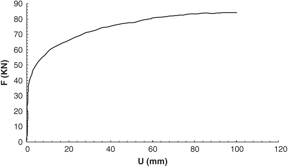
Figure 10: Experimental load-displacement curve
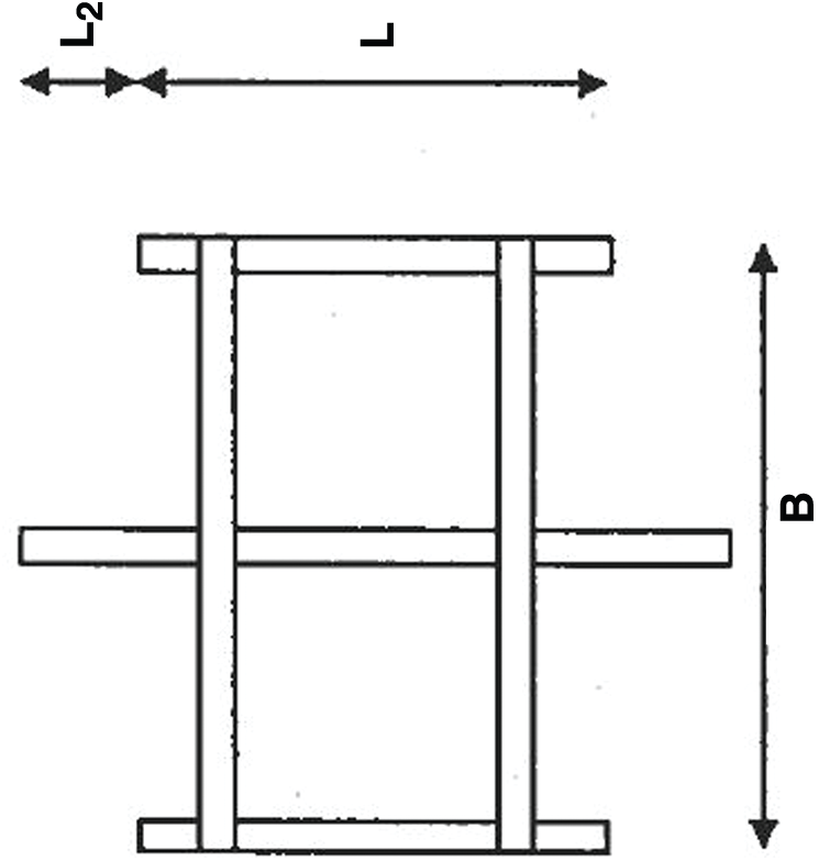
Figure 11: Foundation used in experimental test [26] (L = 1.372 m, L2 = 0 m, B = 1.473, D = 1.61 m where D is the depth)
Displacements of the uplifted and compressed footings
Figs. 12 and 13 indicate the nonlinear displacements variation of the tower support vs. time for Pmax = 60 and Pmax = 100 kN. When Pmax = 60 kN, the compressed footing displacement is 12 mm and it is 4 mm in the case of uplifted footing. Then the uplift is less important than the settlement. However, when Pmax = 100 kN, the uplift displacement is 26 mm which is larger than the compressed footing settlement that is 17 mm. The maximum displacements of the uplifted and compressed footings may be compared using Tabs. 5 and 6.
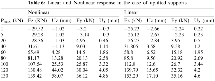
It may be deduced that until the foundation’s carrying capacity is reached, compression displacements are more critical than uplift displacements (about 124 kN). After then, the raised footings’ displacements are larger than the compressed footings’ displacements. The variations in the time of the displacements for Pmax = 60 kN is shown in Fig. 12. Nonlinear displacements and forces are larger than linear displacements and forces for significant applied loads. When 130 kN is applied on the tower top, for example, the linear displacement is around 17 mm, and it is roughly 60 mm when the foundation’s non-linear behavior is taken into consideration. The variations in the time of the displacements for Pmax = 100 kN is shown in Fig. 13. It may be determined that the linear analysis may be utilized to calculate the tower’s reaction for modest deformations (10−3 m). When dealing with substantial deformations, however, the linear assumption is inconvenient. The foundation’s non-linear behavior resulted in increasing the maximum displacement on the b. Base uplifting and soil failure are the causes of large deformations. As shown in Tab. 6, the nonlinear behavior of the foundation causes a slight reduction in the resistance pressures on the TL structural supports as compared to the linear analysis, primarily for large applied-loads.
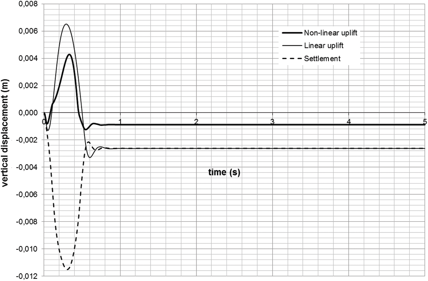
Figure 12: Vertical displacements at the TL base for Pmax = 60 kN
Linear and nonlinear response in the case of uplifted foundation
On Tab. 6, the maximum displacements and resistance forces on the tower uplifted supports are shown. On the tower top, the total applied load varies between 1 and 130 kN. The foundation’s linear and non-linear behavior (soil collapse and foundation uplift) are both evaluated. The values of linear displacement at the base of the tower are larger than the non-linear values from the start of the load application until Pmax equals 60 kN.
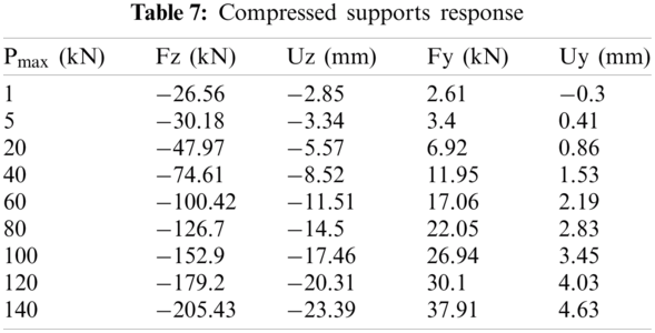
Compressed foundation maximum response
On Tab. 7, the maximum displacement and resistance force values for the tower-compressed supports are shown. On the top of the tower, the total applied load varies between 1 and 140 kN. The displacement of the uplifted footing turn into larger than the displacement of the compressed footing when the load received by the foundation surpasses its bearing capacity (approximately 124 kN), as illustrated in Tabs. 6 and 7. The settlement is more significant than the uplift displacement under the foundation’s bearing capacity, and the settlement is roughly 21 mm near the bearing capacity.
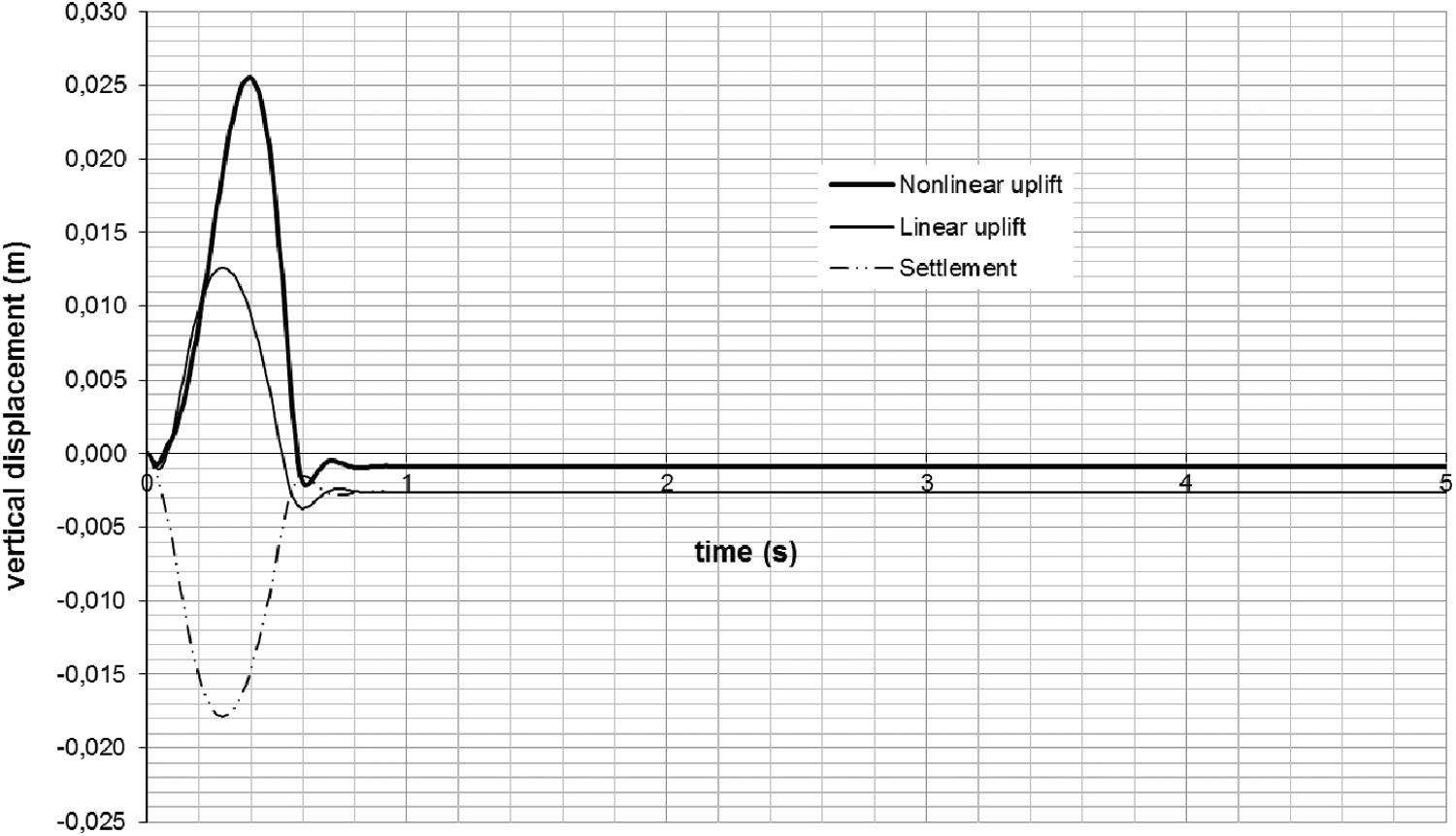
Figure 13: Vertical displacements at the TL base tower for Pmax = 100 kN
In this research, the influence of SSI was investigated using both linear and non-linear foundation behavior. On the basis of soil stiffness and soil damping variation, a linear parametric study was conducted. Analysis in the frequency and temporal domains were carried out. Real foundations with linear and non-linear behavior were investigated in a real case. To get the largest impact on the structure response, an iterative calculation was performed using impedance and checking the value of the system’s frequency each time until a system frequency equal to the frequency calculated using impedances was obtained. This paper’s key results may be summarized as follows:
— Through wave radiation and hysteretic action, a portion of the energy of the vibrating flexibly-supported structure is dissipated into the soil, resulting in a damping ratio greater than that of the comparable fixed-base structure.
— Introducing impedances in place of rigid bases to account for soil structure interaction modifies the dynamic behavior of the soil structure system significantly.
The relevance of addressing the soil structure interaction impact is demonstrated by the values of supports responses under shock loadings. Except for low damping a dynamic reduction was observed, confirming the current dominant opinion in structural engineering that SSI can reduce dynamic load effect when taken into account. However, low soil damping results in increase of dynamic load effect, which might result in a hazardous design. In accordance with the results. It’s worth noting that using linear impedances instead of rigid supports has a considerable impact on the response. As a result, the dynamic tower’s reactive impulse loads are affected by soil structure interaction.
— The impact of SSI may be anticipated using shock spectra curves and analytic formulations of comparable stiffness and damping.
— The use of nonlinear springs in conjunction with experimental force-displacement curves revealed the linear approach’s limitations in the case of significant deformation.
— When the hysteretic behavior of the soil and the possibility of foundation uplift were taken into consideration, the reaction at the base of the TL tower varied when compared to the identical reaction when linear assumptions were used.
— Because TL towers are heavily stimulated by impulsive loads and the risk of substantial deformations and foundation uplift exists, it is vital to evaluate the foundation's non-linear behavior.
— The displacement values obtained on the uplifted footing of the TL tower demonstrate that an uplift of 21 mm is a safe limit for the foundation and the supported structure, and that an uplift of 50 mm poses a risk to the foundation and the supported structure. These results are consistent with typical values used in the field of engineering.
— The effect of soil-structure interaction might have a significant impact on the overall response of the tower, depending on the tower configuration and dynamic loading.
For soils behaving in their quasi-elastic range, the approach utilized in this research can be considered accurate. However, it will be more realistic if the structure’s nonlinear behavior is also taken into account to obtain a better understanding of this complex behavior.
Acknowledgement: The research was performed within the Industrial Research Chair NSERC/HQTE-RTE on Mechanics and Structures of Transmission Lines. The financial support of NSERC and Hydro-Québec TransÉnergy (HQTE) is therefore acknowledged.
Funding Statement: This work was financed by The Natural Sciences and Engineering Research Council of Canada (NSERC) and Hydro-Québec TransÉnergy (HQTE).
Conflicts of Interest: The authors declare that they have no conflicts of interest to report regarding the present study.
1. J. M. Roesset, “A review of soil-structure interaction, soil-structure interaction: The status of current analysis methods and research,” (ed.J. J. Johnson, Report. Nuclear, US, Regulatory Commission and Lawrence Livermore Laboratory, Report No. NUREG/CR-1780 and UCRL-53011, 1980. [Google Scholar]
2. G. Gazetas and G. Mylonakis, “Seismic soil-structure interaction: New evidence and emerging issues,” in Proc. Geotechnical Earthquake Engineering and Soil Dynamics III, ASCE, Seattle, Washington, USA, pp. 1119–1174, 1998. [Google Scholar]
3. G. McClure and M. Lapointe, “Modeling the structural dynamic response of overhead transmission lines,” Computer and Structures, vol. 81, no. 8–11, pp. 825–834, 2003. [Google Scholar]
4. G. B. Warburton, “Soil-structure interaction for tower structures,” Earthquake Engineering & Structural Dynamics, vol. 6, no. 6, pp. 535–556, 1978. [Google Scholar]
5. G. Mylonakis And G. Gazetas, “Seismic soil-structure interaction: Beneficial or detrimental?,” Journal of Earthquake Engineering, vol. 4, no. 3, pp. 277–301, 2000. [Google Scholar]
6. V. Anand and S. R. S. Kumar, “Seismic soil-structure interaction: A state-of-the-art review,” Structures, vol. 16, no. 1, pp. 317–326, 2018. [Google Scholar]
7. G. Gazetas and M. Apostolou, “Nonlinear soil-structure interaction: Foundation uplifting and soil yielding,” in Proc. Third UJNR Workshop on Soil-Structure Interaction, Menlo Park, California, USA, 2004. [Google Scholar]
8. I. Psycharis, “Dynamics of flexible systems with partial lift-off,” Earthquake Engineering and Structural Dynamics, vol. 11, no. 4, pp. 501–521, 1983. [Google Scholar]
9. A. Chopra and S. Yim, “Simplified earthquake analysis of structures with foundation,” Uplift Journal of Structural Engineering, vol. 111, no. 4, pp. 906–930, 1985. [Google Scholar]
10. A. Koh, P. Spanos and J, “Roesset harmonic rocking of rigid block on flexible foundation,” Journal of Engineering Mechanics, vol. 112, no. 11, pp. 1165–1180, 1986. [Google Scholar]
11. C. Cremer, A. Pecker and L. Davenne, “Modeling of nonlinear dynamic behaviour of a shallow strip foundation with Macro-Element,” Journal of Earthquake Engineering, vol. 6, no. 2, pp. 175–211, 2002. [Google Scholar]
12. M. E. Darmian Boostani, M. Azhdary Moghaddam and H. R. Naseri, “Soil-structure interaction in steel braced structures with foundation uplift,” International Journal of Recent Research and Applied Studies, vol. 7, no. 2, pp. 185–191, 2011. [Google Scholar]
13. M. R. Tabeshpour, “Nonlinear analysis of chimney like towers,” Asian Journal of Civil Engineering (Building And Housing), vol. 13, no. 1, pp. 97–112, 2012. [Google Scholar]
14. B. Erkmen, “Evaluation of code provisions for seismic performance of unanchored liquid storage tanks,” in Proc. COMPDYN 2017, Rhodes Island, Greece, 2017. [Google Scholar]
15. J. G. Sieffert and C. Franck, Manuel des fonctions d'impédance – Fondations superfcielles. France: Presses Académiques Edition, 1991. [Google Scholar]
16. G. Gazetas, “Formulas and charts for displacements of surface and embedded foundations,” Journal of Geotechnical Engineering, vol. 117, no. 9, pp. 1363–1381, 1991. [Google Scholar]
17. A. Jendoubi, M. Karray and F. Legeron, “Displacement functions for layered and inhomogeneous soils,” International Journal of Geotechnical Engineering, vol. 5, no. 2, pp. 151–163, 2011. [Google Scholar]
18. G. Gazetas and J. M. Roesset, “Vertical vibration of machine foundations,” Journal of the Geotechnical Engineering Division, vol. 105, no. GT12, pp. 1435–1454, 1979. [Google Scholar]
19. W. R. Clough and J. Penzien, Dynamics of structures, 3rd ed., USA: Dynamics of Structures Inc., 1995. [Online]. Available at: https://www.chaocompute.com/wp-content/uploads/2020/07/Dynamics-of-Structures-Clough-Penzien.pdf. [Google Scholar]
20. Engineering Simulation Software Program developed and distributed worldwide by ADINA R&D, Inc., Watertown, USA. [Online]. Available: http://www.adina.com. [Google Scholar]
21. A. Jendoubi, “Effet de l’interaction dynamique linéaire et non linéaire sol-structure: Application aux pylônes de transport d’énergie,” Thèse de doctorat, Université de Sherbrooke, 2015. [Google Scholar]
22. S. Kramer, Geotechnical Earthquake Engineering. New Delhi: Pearson Education Publication, 2004. [Google Scholar]
23. C. Indrajit and P. D. Shambhu, Dynamic of Structure and Foundation—A Unified Approach. London: CRC Press, Taylor and Francis Group, 2008. [Google Scholar]
24. Working group CIGRE B2-08, “The effect of fabrication and erection imperfections of Lattice Steel Transmission Towers. Cigre India, Electra,” 2010. [Online]. Available: https://cigreindia.org/CIGRE%20Lib/Tech.%20Brochure/428%20Fabrication%20%20Errors%20%20i%20%20Erection%20znd%20strength%20%20oif%20towersErectio.pdf. [Google Scholar]
25. A. Jendoubi and F. Legeron, “Effect of the dynamic soil -structure interaction on rigid transmission line towers subjected to wind and impulse loads, Electrical Transmission and Substation Structures 2012: Solutions to Building the Grid of Tomorrow,” in Proc. of the 2012 Electrical Transmission and Substation Structures Conf., Columbus, Ohio, USA, pp. 250–261, 2012. [Google Scholar]
26. P. Trudel and N. Lemieux, Amélioration de la robustesse des lignes de transport – Essais d’arrachement sur fondations existantes de type grillage métallique. Montreal: Hydro-Quebec, 2005. [Google Scholar]
 | This work is licensed under a Creative Commons Attribution 4.0 International License, which permits unrestricted use, distribution, and reproduction in any medium, provided the original work is properly cited. |