DOI:10.32604/cmc.2022.019397
| Computers, Materials & Continua DOI:10.32604/cmc.2022.019397 | |
| Article |
Efficient Gauss-Seidel Precoding with Parallel Calculation in Massive MIMO Systems
1Department of Information and Communication Engineering, Convergence Engineering for Intelligent Drone, Sejong University, Seoul, 05006, Korea
2Department of Convergence Engineering for Intelligent Drone, Sejong University, Seoul, 05006, Korea
3Department of Computer Engineering, Convergence Engineering for Intelligent Drone, Sejong University, Seoul, 05006, Korea
*Corresponding Author: Hyoung-Kyu Song. Email: songhk@sejong.ac.kr
Received: 12 April 2021; Accepted: 18 May 2021
Abstract: A number of requirements for 5G mobile communication are satisfied by adopting multiple input multiple output (MIMO) systems. The inter user interference (IUI) which is an inevitable problem in MIMO systems becomes controllable when the precoding scheme is used. In this paper, the horizontal Gauss-Seidel (HGS) method is proposed as precoding scheme in massive MIMO systems. In massive MIMO systems, the exact inversion of channel matrix is impractical due to the severe computational complexity. Therefore, the conventional Gauss-Seidel (GS) method is used to approximate the inversion of channel matrix. The GS has good performance by using previous calculation results as feedback. However, the required time for obtaining the precoding symbols is too long due to the sequential process of GS. Therefore, the HGS with parallel calculation is proposed in this paper to reduce the required time. The rows of channel matrix are eliminated for parallel calculation in HGS method. In addition, HGS uses the ordered channel matrix to prevent performance degradation which is occurred by parallel calculation. The HGS with proper number of parallelly computed symbols has better performance and reduced required time compared to the traditional GS.
Keywords: Massive MIMO; GS; matrix inversion; linear precoding
Multiple input multiple output (MIMO) systems are key components of future wireless communication in terms of high data rate over a limited frequency resource [1,2]. Massive MIMO systems are specific cases of MIMO systems. The number of base station (BS) antennas is much larger than the number of antennas for terminals in massive MIMO systems. In massive MIMO systems, the inter user interference (IUI) which is an inevitable problem in MIMO systems becomes controllable when the precoding scheme is used. The precoding schemes in massive MIMO systems have been studied as promising techniques which achieve spatial multiplexing gain to increase throughput and spatial diversity to improve reliability at 5G [3–8]. The massive MIMO systems promise significant improvements in terms of spectral efficiency, reliability, and data rate compared to multi-user (MU) MIMO systems by using large channel matrix [9–11]. The significant improvement of performances for the massive MIMO is shown mathematically in [12]. If the channel matrix is extremely large, the effect of fast fading and non-correlated noise becomes extinct [13]. However, computational complexity at BS is extremely increased because of large array of antennas at BS. The inversion of the channel matrix is critical task for massive MIMO signal processing [14]. It means that the precoding schemes which use exact inversion of channel matrix are impractical in massive MIMO systems. Therefore, the schemes which use approximated matrix inversion have been studied for achieving low computational complexity in massive MIMO systems.
The match filter (MF) precoding is the simplest precoding scheme. However, the performance of the MF precoding is much poorer than the ZF scheme [9]. The ZF scheme at MU-MIMO systems has sub-optimal performance and the lowest computational complexity. In contrast, the ZF in massive MIMO systems has optimal performance because of the large channel matrix [15]. However, in massive MIMO systems, since the inversion of large gram matrix has to be calculated, ZF scheme has impractically large computational complexity which is cubic order with respect to the number of users.
Therefore, in [16], the approximate inversion of gram matrix is calculated by using Neumann Series (NS). The computational complexity of approximate inversion using NS is lower than exact inversion and the calculation of NS is parallelized. However, when the iteration of NS is more than 2, NS has also computational complexity which is cubic order.
In contrast, precoding scheme based on Gauss-Seidel (GS) which was proposed in [17] keeps the computational complexity which is square order. In addition, since the result of the previous precoding symbol is used as the feedback of the following calculation of next precoding symbol, the performance of the scheme based on GS is better than the scheme based on NS. It means that the calculation at GS is not parallel processing and requires longer time for obtaining precoding symbol.
Therefore, in this paper, horizontal GS (HGS) which reduces required time for obtaining precoding symbol is proposed. The HGS calculates some precoding symbols without feedback of the previous precoding symbol for parallel processing. The conventional schemes use calculation result of previous symbol for calculating present symbol. It means that conventional schemes have to wait for result of the
In Section 2, system model which is used in this paper is explained. The conventional schemes which are compared with the proposed scheme are explained in Section 3. In Section 4, HGS scheme is proposed. Section 5 shows the performance comparison between the conventional schemes and the proposed scheme.
In Fig. 1, massive MIMO broadcasting system which is composed of one base station with
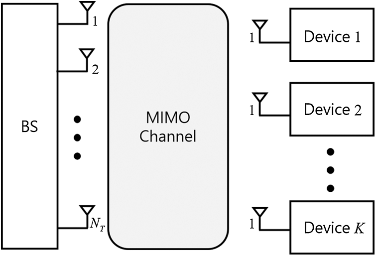
Figure 1: System model of the downlink massive MIMO channel
The transmit signal vector for the
where
The set of entire received signal vectors
where
Diagonal components in the effective channel matrix are MIMO channels for each user and off-diagonal components express the IUI.
The ZF precoding scheme uses exact inversion of the gram matrix to eliminate IUI and inter antenna interference (IAI). The precoding matrix of ZF can be expressed as follows,
where
The precoded signal vector can be expressed as follows,
where
For downlink massive MIMO systems, the columns of channel matrix
The GS method is an iterative technique for solving linear equation
where
where
The GS method can be applied to linear equation
where
It means that the components of
4 Proposed Horizontal Gauss-Seidel Precoding
The ZF precoding scheme has optimal performance with large scale MIMO systems. However, when the ZF is used, large computational complexity of exact matrix inversion is inevitable. Therefore, the methods which compute approximate inversion of channel matrix with low complexity have been studied such as GS method. In GS method, the results of the precoding symbol from the first to the
Fig. 2 is the flow chart of the HGS in massive MIMO systems. The parallel calculation at GS method means the calculation of current precoding symbol without feedback. The precoding symbols which are computed without feedback have to be chosen for parallel calculation. Therefore, the criterion for choosing the precoding symbols without feedback has to be defined. For example, when
For example, Fig. 3 shows lower triangular matrix
The components which are excluded from
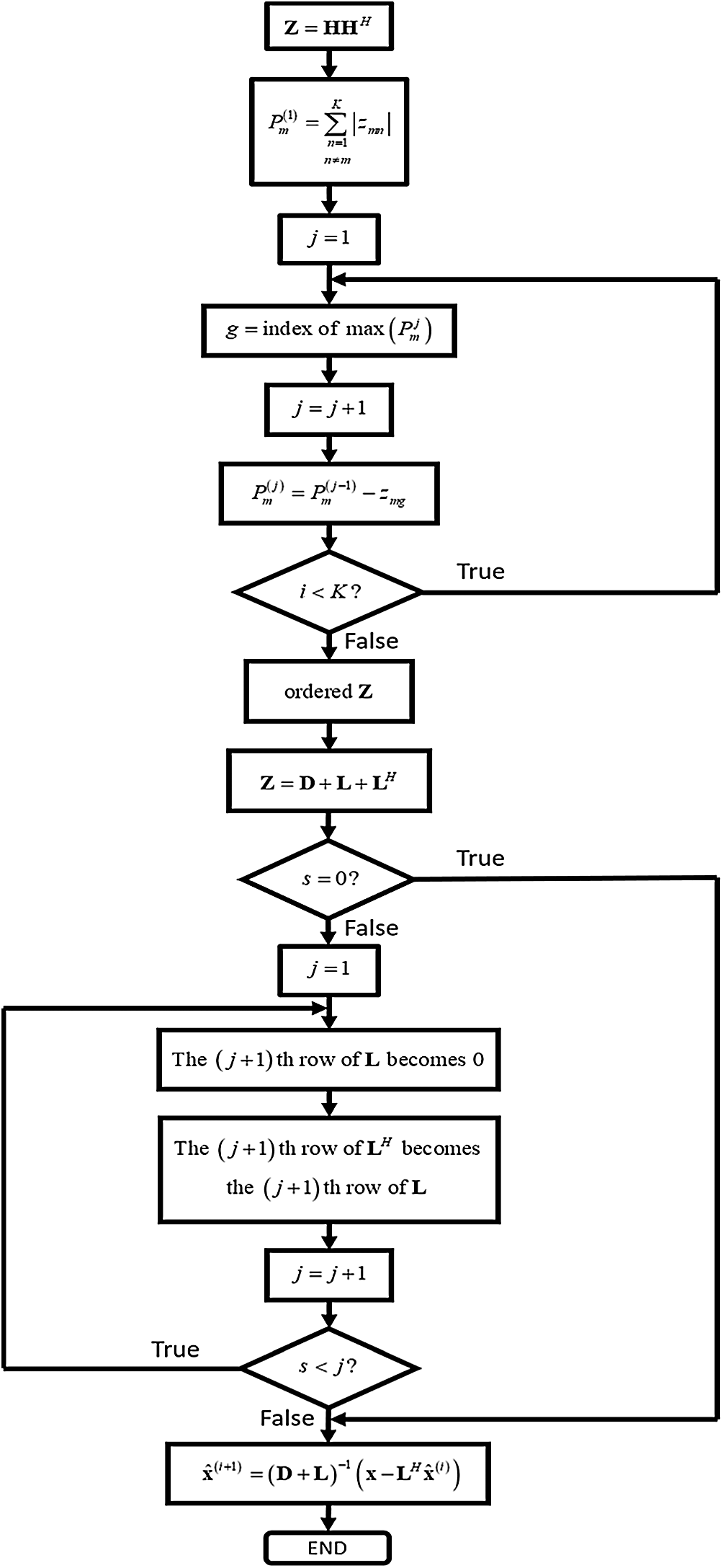
Figure 2: Flow chart of HGS in massive MIMO systems
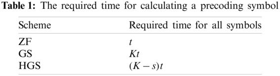
The required time for calculating a precoding symbol is shown in Tab. 1. If the required time for calculating a precoding symbol is t, the
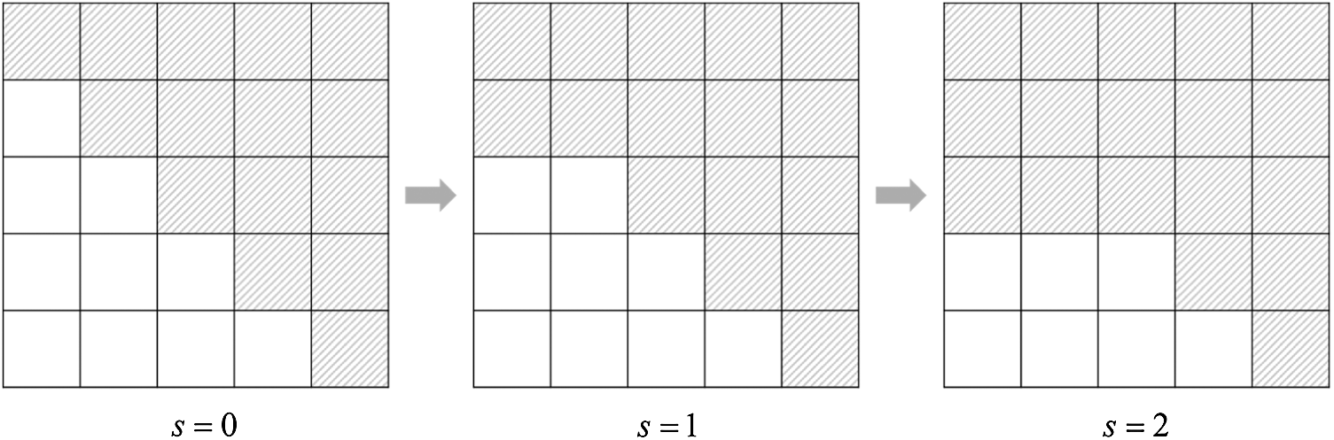
Figure 3: Lower triangle matrix
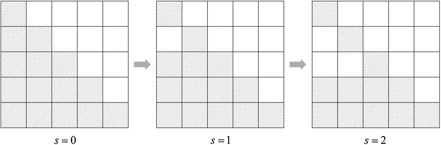
Figure 4: Upper triangle matrix
The performance degradation of the HGS can be prevented by sorting the gram matrix of the channel. The criterion of sorting the gram matrix is the off-diagonal components of
The off-diagonal components of the gram matrix mean the correlation with other channels. The large correlation with other channels means that the interference from other channels is large. Therefore, the symbol which has the channel corresponding to large off-diagonal components needs many feedbacks. It means that the row of gram matrix with maximum off-diagonal components should replace the bottom of the matrix. If the
The row with maximum
where the g is the index of the row with maximum
Since the approximation of HGS rapidly gets close to the exact inversion of the gram matrix, the performance of HGS is better than the conventional GS. However, the GS has better convergence rate by using only sequential calculation. The HGS overcomes poor convergence rate by sorting the gram matrix. The approximation error between approximate solution and exact solution can be expressed as follows,
where the
where
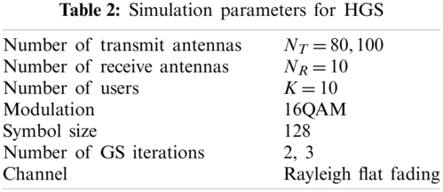
The error and throughput performances for the HGS are evaluated and compared with the conventional GS scheme. The Rayleigh flat fading channel is used and the perfect channel estimation is assumed. All elements of the channel matrices have independent complex Gaussian random variables with zero mean and unit variance. The system which has much larger number of transmit antennas compared to the number of receive antennas is considered. The number of transmit antennas is 80 or 100. The number of antennas for each user is 1 and total number of receive antennas is 10. The used modulation is 16-quadrature amplitude modulation (QAM). The number of GS iterations is 2 or 3. The number of precoding symbols which are computed parallelly at HGS is 0, 2 or 5. The bit error rate (BER) performances for the HGS are evaluated with various number of parallelly calculated symbols. Tab. 2 shows the simulation parameters.
The BER and throughput performances for the HGS are shown in Figs. 5–8. The enhancement of the BER performance at HGS is obtained by ordering the gram matrix of the channel. The performances with 2 GS iterations are shown in Fig. 5. Since the performance enhancement is occurred by ordering gram matrix but the performance degradation of parallel calculation is not occurred, the HGS without parallel calculation (HGS-0) has the best performance. Therefore, the throughput of HGS-0 is larger than other schemes in Fig. 7a. In Fig. 7b, the gap of throughput between the schemes except HGS-5 is small. However, the HGS without parallel calculation has the same required time for obtaining precoding symbol as conventional GS. The HGS with 2 symbols which are parallelly computed (HGS-2) has better performance compared to the conventional GS. In Fig. 7a, HGS-2 achieves the maximum throughput rapidly compared to the conventional GS. In addition, the required time for calculating precoding symbol is reduced compared to the conventional GS due to the parallel calculation. However, since the number of feedback at HGS-2 is smaller than the feedback at HGS-0, the BER performance of HGS-2 is poorer than HGS-0. The throughput of HGS-2 is slightly smaller than HGS-0 in Fig. 7a. However, the throughput performances of HGS-0 and HGS-2 are almost same in Fig. 7b. When the number of symbols which are computed parallelly is larger than
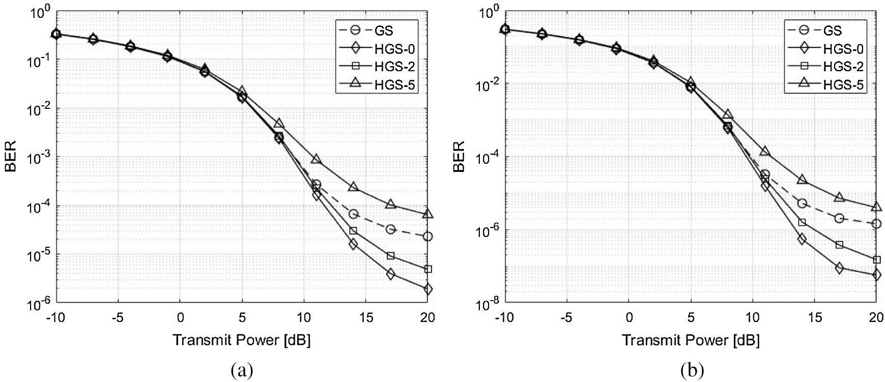
Figure 5: BER performance comparison with 2 GS iterations between the GS and the proposed HGS. (a) 2 GS iterations and
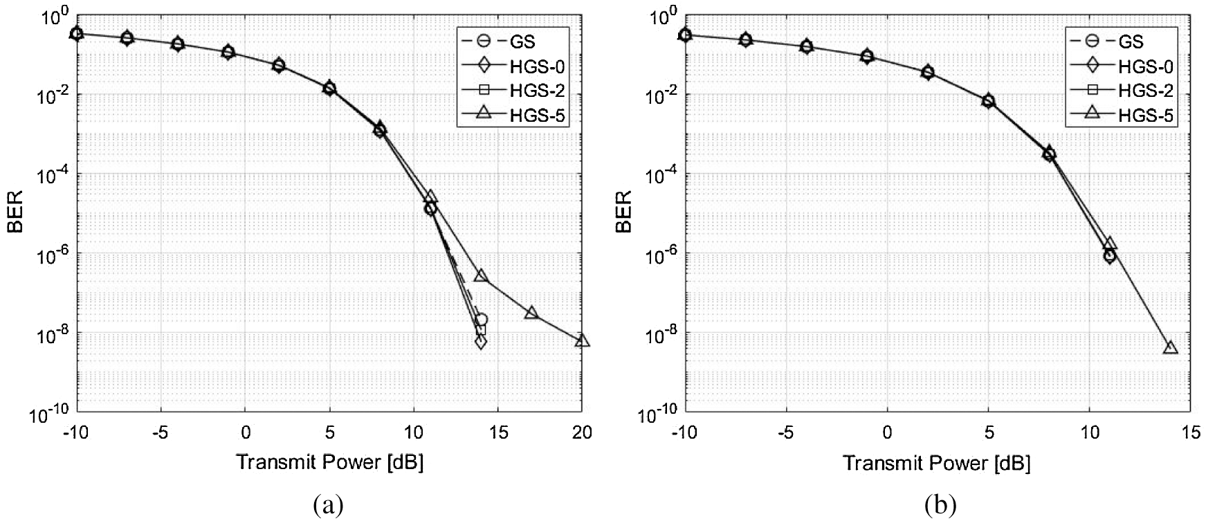
Figure 6: BER performance comparison with 3 GS iterations between the GS and the proposed HGS. (a) 3 GS iterations and
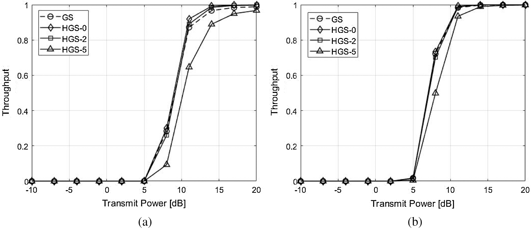
Figure 7: Throughput performance comparison with 2 GS iterations between the GS and the proposed HGS. (a) 2 GS iterations and

Figure 8: Throughput performance comparison with 3 GS iterations between the GS and the proposed HGS. (a) 3 GS iterations and
The BER and throughput performances with 3 GS iterations are shown in Figs. 6 and 8. Since the 1 GS iteration is added, the approximate solution becomes close to the exact solution. Therefore, the performances of all schemes with 3 GS iterations are better than the performances of all schemes with 2 GS iteration. In addition, the GS, HGS-0 and HGS-2 have almost optimal BER performance. However, the HGS-5 has poorer performance compared to other schemes due to parallel calculation of many symbols in Fig. 6a. The HGS-5 has almost similar performance with other schemes due to diagonal dominant channel in Fig. 6b. The all schemes have almost optimal throughput performance due to added GS iteration in Fig. 8.
The comparison of Frobenius norm is shown in Fig. 9. Since precoding symbols of the GS and HGS-0 are calculated with whole lower and upper triangular matrix for sequential calculation, the GS and HGS-0 have the smallest Frobenius norm. In addition, since the HGS-0 has performance enhancement by sorting the gram matrix, the HGS-0 has better BER performance compared to conventional GS. Since the lower triangular matrix without 2 rows is used at calculation, the HGS-2 has slightly large Frobenius norm compared to GS and HGS-0. However, the HGS-2 overcomes the reduced Frobenius norm by sorting the gram matrix. Therefore, the performance of HGS-2 is better than the GS although the Frobenius norm of the HGS-2 is larger than GS. Since the HGS-5 has too many symbols which are calculated parallelly, the difference of Frobenius norm between GS and HGS-5 becomes large. Therefore, the HGS-5 can not overcome the reduced Frobenius norm even though the HGS-5 uses the ordered gram matrix. The BER performance of HGS-5 is poorer than the GS because of the reduced Frobenius norm.
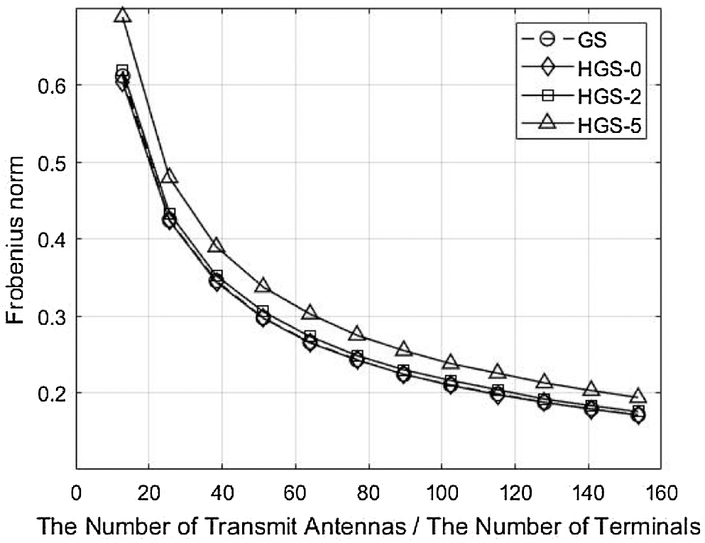
Figure 9: Comparison of Frobenius norm with
Massive MIMO system is a key component of future wireless communication in terms of high data rate over a limited frequency resource. In MIMO broadcast channel, IUI occurs inevitably at each device. Therefore, the BS has to utilize precoding schemes for IUI reduction.
The HGS with parallel operation is proposed to reduce the required time for obtaining the precoding symbol in massive MIMO systems. The conventional GS method has performance enhancement due to the sequential calculation which uses previous results as feedback. It means that the required time for obtaining the precoding symbols is too long. When the required time for obtaining one precoding symbol is t, the total required time at GS is
Funding Statement: This research was supported by Basic Science Research Program through the National Research Foundation of Korea(NRF) funded by the Ministry of Education (2020R1A6A1A03038540) and was supported by the National Research Foundation of Korea(NRF) Grant funded by the Korea government (MSIT) (2021R1A2C2005777).
Conflicts of Interest: The authors declare that they have no conflicts of interest to report regarding the present study.
1. P. Li, Y. Gao, Z. Li and D. Yang, “Pilot sequence assignment for spatially correlated massive MIMO circumstances,” KSII Transactions on Internet and Information Systems, vol. 13, no. 1, pp. 237–253, 2019. [Google Scholar]
2. P. I. Tebe, G. Wen, J. Li, Y. Huang, A. E. Ampoma et al., “Massive MIMO with transceiver hardware impairments: Performance analysis and phase noise error minimization,” KSII Transactions on Internet and Information Systems, vol. 13, no. 5, pp. 2357–2380, 2019. [Google Scholar]
3. Q. Deng, X. Liang, X. Wang, M. Huang, C. Dong et al., “Fast converging iterative precoding for massive MIMO systems: An accelerated Weighted neumann series-steepest descent approach,” IEEE Access, vol. 8, pp. 50244–50255, 2020. [Google Scholar]
4. Y. Liu, J. Liu, Q. Wu, Y. Zhang and M. Jin, “A near-optimal iterative linear precoding with low complexity for massive MIMO systems,” IEEE Communications Letters, vol. 23, no. 6, pp. 1105–1108, 2019. [Google Scholar]
5. J. Ø. Nielsen, A. Karstensen, P. C. F. Eggers, E. De Carvalho, G. Steinböck et al., “Precoding for TDD and FDD in measured massive MIMO channels,” IEEE Access, vol. 8, pp. 193644–193654, 2020. [Google Scholar]
6. J. Chen, “Low-cost and power-efficient massive MIMO precoding: Architecture and algorithm designs,” IEEE Transactions on Vehicular Technology, vol. 69, no. 7, pp. 7429–7442, 2020. [Google Scholar]
7. M. A. M. Albreem, A. A. El-Saleh and M. Juntti, “Linear massive MIMO uplink detector based on joint jacobi and gauss-seidel methods,” in 2020 16th Int. Conf. on the Design of Reliable Communication Networks DRCN 2020, Milano, Italy, pp. 1–4, 2020. [Google Scholar]
8. R. Chataut, R. Akl and M. Robaei, “Accelerated and preconditioned refinement of gauss-seidel method for uplink signal detection in 5G massive MIMO systems,” in 2020 10th Annual Computing and Communication Workshop and Conf. (CCWCLas Vegas, NV, USA, pp. 83–89, 2020. [Google Scholar]
9. F. Rusek, D. Persson, B. K. Lau, E. G. Larsson, T. L. Marzetta et al., “Scaling up MIMO: Opportunities and challenges with very large arrays,” IEEE Signal Processing Magazine, vol. 30, no. 1, pp. 40–60, 2013. [Google Scholar]
10. H. Huh, G. Caire, H. C. Papadopoulos and S. A. Ramprashad, “Achieving massive MIMO spectral efficiency with a not-so-large number of antennas,” IEEE Transactions on Wireless Communications, vol. 11, no. 9, pp. 3226–3239, 2012. [Google Scholar]
11. H. Q. Ngo, E. G. Larsson and T. L. Marzetta, “Energy and spectral efficiency of very large multiuser MIMO systems,” IEEE Transactions on Communications, vol. 61, no. 4, pp. 1436–1449, 2013. [Google Scholar]
12. T. L. Marzetta, “Noncooperative cellular wireless with unlimited numbers of base station antennas,” IEEE Transactions on Wireless Communications, vol. 9, no. 11, pp. 3590–3600, 2010. [Google Scholar]
13. I. A. Khoso, X. Dai, M. N. Irshad, A. Khan and X. Wang, “A low-complexity data detection algorithm for massive MIMO systems,” IEEE Access, vol. 7, pp. 39341–39351, 2019. [Google Scholar]
14. C. Tang, C. Liu, L. Yuan and Z. Xing, “High precision low complexity matrix inversion based on newton iteration for data detection in the massive MIMO,” IEEE Communications Letters, vol. 20, no. 3, pp. 490–493, 2016. [Google Scholar]
15. X. Gao, O. Edfors, F. Rusek and F. Tufvesson, “Linear pre-coding performance in measured very-large MIMO channels,” in 2011 IEEE Vehicular Technology Conf. (VTC FallSan Francisco, CA, pp. 1–5, 2011. [Google Scholar]
16. H. Prabhu, J. Rodrigues, O. Edfors and F. Rusek, “Approximative matrix inverse computations for very-large MIMO and applications to linear precoding systems,” in 2013 IEEE Wireless Communications and Networking Conf. (WCNCShanghai, pp. 2710–2715, 2013. [Google Scholar]
17. L. Dai, X. Gao, X. Su, S. Han, I. Chih-Lin et al., “Low-complexity soft-output signal detection based on gauss–seidel method for uplink multiuser large-scale MIMO systems,” IEEE Transactions on Vehicular Technology, vol. 64, no. 10, pp. 4839–4845, 2015. [Google Scholar]
18. W. S. Lee, J. Y. Jang, J. H. Ro, J. Kim and H. K. Song, “An efficient modified gauss-seidel precoder for downlink massive MIMO systems,” IEEE Access, vol. 8, pp. 202164–202173, 2020. [Google Scholar]
19. G. H. Golub, and C. F. Van Loan, “Matrix computations,” Google Scholar, vol. 3, pp. 111263–112264, 2012. [Google Scholar]
 | This work is licensed under a Creative Commons Attribution 4.0 International License, which permits unrestricted use, distribution, and reproduction in any medium, provided the original work is properly cited. |