DOI:10.32604/cmc.2022.019495
| Computers, Materials & Continua DOI:10.32604/cmc.2022.019495 | |
| Article |
Helix Inspired 28 GHz Broadband Antenna with End-Fire Radiation Pattern
1School of Engineering, Faculty of Science and Engineering, Macquarie University, Sydney, NSW, 2109, Australia
2Department of Integrated IT Engineering, Seoul National University of Science and Technology, Seoul, 01811, Korea
3Department of Information and Communication Engineering, Chungbuk National University, Chungbuk, 28644, Korea
4BENELEC, Botany, Sydney, NSW, 2019, Australia
*Corresponding Author: Niamat Hussain. Email: hussain@chungbuk.edu.kr
Received: 15 April 2021; Accepted: 24 May 2021
Abstract: This paper presents the design and characterization of a via free planar single turn helix for 28 GHz broadband applications. The proposed antenna is designed using ROGERS RO4003 material, having a simple structure and end-fire radiation pattern. The antenna comprises of a compact dimension of 1.36 λ0 × 0.9 λ0 with a thickness of 0.0189 λ0 (where λ0 is the free-space wavelength at the central frequency of 28 GHz). Parametric study has been carried out to investigate the impact of key design parameters and to achieve an optimum design. Results show a good agreement between the simulated and measured results. A single turn helical inspired antenna covers −10 dB impedance bandwidth of 26.25–30.14 GHz having a peak gain of 5.83 dB and radiation efficiency up to 85%. Moreover, linear array configurations with 2 and 4 elements have been analyzed for applications with higher gain and space constraints. Presented array configurations are suitable for applications having space constraints in one dimension. Results show that peak gain up to 8.2 dB and 11.1 dB can be achieved with 2 and 4 elements, respectively. Due to its simple planar and via free structure, this antenna is suitable for 5G communications and for sensing, imaging, IoT and tracking applications at 28 GHz band spectrum.
Keywords: Compact antenna; millimeter wave antenna; 28 GHz; 5G antenna
The fifth generation (5G) of mobile communications promised higher Gbps data rates with very low latency to support the ever-increasing number of users. The higher data rates are directly associated to bandwidth, therefore radio frequency (RF) front ends operating at millimeter-wave part of the spectrum have drawn significant attention of the researchers [1]. It also provides better communication services for all use cases of 5G, namely, Enhanced Mobile Broadband (eMBB), Machine Type Communication (MTC) and Ultra-reliable Low-latency Communication (URLLC) [2]. However, high atmospheric absorption at the mm-wave frequencies requires antennas with high gain and increased directivity. In order to achieve these propitious characteristics promised by the 5G standards, suitable antennas characterized by a compact size, a large bandwidth, as well as a high gain are strongly required [3,4].
Recently, various studies are conducted to obtain antenna designs to fulfill the requirements of future wireless communication technologies. The antennas capable of end fire radiation with high gain and increased directivity are prominent among these designs [5–10]. Several designs have been reported for 5G mm-wave applications [11–21]. A dual polarized end-fire phased array, with 4 elements, having 25% bandwidth at −6 dB matching is presented. The reported gain is 7.48–8.14 dBi and 4.49–8.05 dBi, for horizontal and vertical polarizations, respectively [11]. Similarly, 8-element reconfigurable phased array with planar structure has reported gain of about 10 dBi and 4.3 dBi for single element in end-fire mode [12], whereas, 4-element reconfigurable phased array with gain in the range of 5.3–8.2 dBi for end-fire mode has also been presented [13]. Hong et al. reported 16-element mesh-grid patch antenna array where the single element has gain of 3.5 dBi [14], whereas, Ta et al. has reported 8-element array with planar single element having gain of 4.5–5.8 dBi [15]. A MIMO antenna consisting of radiating patch with air filled slots demonstrated gain of 5.13 dBi [16]. It can be deduced from the above discussion that single element with lower gains were used to achieve higher gains [11–16]. Here the presented antenna has measured gain in the range of 4 to 6 dB, which is suitable for 5G mm-wave applications.
In addition, various helical antennas are reported exhibiting higher gain and directivity, as well as large operational bandwidth [17–22]. However, the conventional helical antennas suffer from the main shortcoming of high profile with increased physical height. Consequently, this led the researchers to conduct studies in order to obtain a compact helical antenna with low profile, however maintaining the merits of high gain and directivity as required by the future communication systems. Therefore, planar helix antennas are realized by the researchers, especially for the mm-wave frequency range. In [19], a low-profile helical antenna is proposed, where the antenna is realized to be planar with printed strips and plated via holes to obtain wideband and end-fire radiation pattern. In [20], a wideband printed antenna based on the classical end fire-mode helical antenna with curved microstrip transmission lines is proposed. The antenna array obtains very high gain, however the design has increased fabrication complexity. In [21], planar configuration is employed to obtain a low-profile helical antenna with reduced length. The proposed antenna is composed of 6 arm patterns placed on the top and bottom side of the substrate and connected through vias. Another work in [22] presented a compact wideband end fire antenna using planar technology. The antenna is designed using two Rogers 4350 PCBs adhered together to form an RF PCB with approx. 3 mm thickness. This helix antenna obtains compactness, wide bandwidth, and high gain. The helical antenna designs discussed above are planar and compact in structure however multiple vias are integrated to connect the upper and bottom helical arms, which increases the level of complexity as well as the manufacturing cost of the design.
Therefore, in order to address the aforementioned challenges this paper presents a 5G broadband antenna inspired by the planar helix-shaped antenna. The major contribution of the proposed work can be summarized as follows:
• The presented work is characterized by simple geometrical structure, compact size, broad bandwidth, and high gain.
• The presented work was inspired by helix antennas without employing any vias, thus significantly reducing the design complexity of end-fire antennas.
• Strong agreement between simulated and measured results makes the proposed work a potential candidate for 5G communications and for sensing, tracking, internet of things (IoT), and imaging applications using 28 GHz frequency band.
2 Antenna Design and Characterization
Figs. 1a–1c depicts the top, bottom and side geometrical configuration of the proposed end-fire antenna. The geometry of the proposed antenna is imprinted on 0.203 mm thick ROGERS RO4003 substrate having ɛr = 3.38 and tanδ = 0.0027. Grounded Co-Planar Waveguide (GCPW) technique is utilized to excite the antenna having partial ground plane as depicted in Fig. 1. A hole is etched from substrate and CPW ground plane for the insertion of the screw of end launch connector used for testing purpose. The end launch connector has been used to demonstrate the concept due its better performance and ease of usage at 28 GHz mm-wave designs [23–27].

Figure 1: Geometry of proposed end-fire antenna (a) top view (b) bottom view (c) side view
The antenna design consists of three major steps as depicted in Fig. 2a. In step-1, a T-shaped printed antenna is designed to resonate at 28 GHz, the resultant antenna shows impedance bandwidth ranging 27.8 – 28.4 GHz, as depicted in Fig. 2. For the desired central frequency, the length of the T-shaped antenna could be estimated by using the relations provided in [28]. Afterwards, the T-shaped antenna is modified by utilizing asymmetric CPW virtual ground. Due to the asymmetric geometrical structure, the antenna starts exhibiting an end-fire radiation pattern having a broad bandwidth of 26.9 to 31.1 GHz. Detailed numerical analysis is performed to get the wide bandwidth having maximum achievable gain.
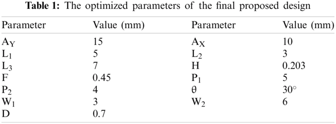
At last, in step-3, another rectangular strip is added to one end of a modified T-shaped radiator at an angle of θ = 30°. The angle between two arms of the radiator was numerically investigated and an optimized value of θ = 30° is chosen to get maximum bandwidth and gain in end-fire direction. In [26] researcher provides a detail discussion on theoretical and mathematical analysis on choosing the angle between two arms and its effect on various performance parameters. The resultant geometry is inspired by a single turn planar helical antenna without utilizing any vias. The resultant antenna shows a −10 dB impedance bandwidth of 26.15 to 29.8 GHz, as depicted in Fig. 2a. It is worth noting that the dimension of the ground plane at the back of the substrate remains unchanged for all three steps. Tab. 1 presents the various parameters of the optimized antenna.

Figure 2: (a) Predicted |S11| comparison of various steps in evolution of the proposed antenna (b) Parametric analysis of the angle (θ) between two arms of the proposed antenna design
The angle (θ) between the arms of the helix, also known as pitch angle, is one of the key parameters in designing helix antennas. A parametric analysis of the pitch angle is performed to investigate its effects on the performance of the design. It is observed from Fig. 2b, that when the pitch angle is shifted from 30° to 15°, the resonance of the antenna is shifted to higher frequencies. Contrary to this, when the angle is changed from 30° to 45°, the antenna shifts its resonance toward the lower side and a small decrement in bandwidth along with the impedance mismatch is also noted. Mismatch and frequency shift towards the lower side is also noted when pitch angle is further changed to 60° and 90°. Thus, it can be concluded from the analysis that for desired applications the optimized pitch angle is 30°, as depicted in Fig. 2b.
To validate the performance of the proposed broadband antenna a sample prototype is fabricated and tested, as shown in the inset of Fig. 3. The s-parameters for the simulated and measured case of the proposed antenna are shown in Fig. 3. The simulated −10 dB impedance bandwidth is observed to be 3.65 GHz ranging from 26.15 to 29.8 GHz while the measured bandwidth is observed to 3.89 GHz ranging 26.25 – 30.14 GHz, as depicted in Fig. 3. It is worth noting that the operational bandwidth of the antenna covers the frequency band spectrum (26.5–29.5 GHz) allocated for 5G mm-wave applications.

Figure 3: Comparison of simulated and measured return loss of proposed antenna
Fig. 4 show the current distribution on the antenna. It can be noted that the stronger currents are present at the longer edge of the T-shaped radiator and extended radiator connected to it at the pitch angle. It can also be deduced from the parametric analysis presented in Fig. 2 that with the smaller pitch angle (i.e., 15°) the currents in the arms of the vertex becomes more parallel and with opposing impact. For other values, the current has less coupling between the arms of the vertex, thus strong resonance is observed.
Fig. 5 presents the comparison among numerically predicted and measured radiation patterns of the proposed antenna. It can be seen from the Fig. 5 that the antenna exhibits end-fire radiation pattern at 28 GHz with the main beam pointed toward θ = 255° in principle E-Plane (Φ = 0°) while the main beam is pointed toward θ = 235° in principle H-plane (Φ = 90°). The antenna has simulated peak gain of 5.92 dB. Fig. 6 illustrates the comparison among simulated and measured peak gain along with numerically calculated radiation efficiency. The proposed broadband antenna exhibits a peak gain of 5.83 dB at 28 GHz while the radiation efficiency up to 85% is noted.

Figure 4: Current distribution of the proposed antenna at 28 GHz

Figure 5: Comparison of simulated and measured radiation pattern at 28 GHz (a) E-plane (b) H-plane
The proposed design has further been analyzed for linear array configurations where higher gain will be desired. The linear array will be more suitable for applications with size constraints in one dimension. Linear array of 2 and 4 elements with in-phase feed and side-by-side arrangement as shown in Fig. 7 has been investigated. The distance (d) is half wavelength from edge of the radiating element to the edge of the other adjacent radiating element. Center to center distance (d) is not considered due to the size of the connector. By controlling the phase delay in feeding the elements, the radiation beam can be tilted. MIMO (Multiple Input Multiple Output) configurations with side-by-side and orthogonal arrangements are suitable for diversity applications [29–32]. As shown in Fig. 8a gain of 8.23 dB and 11.10 dB has been noted for linear array of 2 and 4 elements, respectively.

Figure 6: Comparison of simulated and measured peak gain of the proposed antenna along with its radiation efficiency

Figure 7: Array configuration for (a) 2 elements array (b) 4 elements array

Figure 8: Predicted radiation pattern at 28 GHz for (a) 2 elements array (b) 4 elements array
3.5 Comparison with State of the Art Work
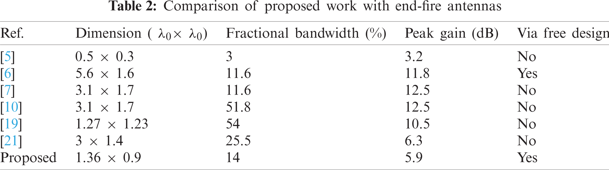
Tab. 2 summarizes the comparison of the proposed antenna with recently reported antennas exhibiting analogous features. It is evident from this comparison that the antenna proposed in this work outperforms the other similar antennas by demonstrating compact size with large fractional bandwidth and sufficient gain. In addition, the proposed design is via free, whereas the other designs incorporated vias which increases the structural complexity and thus limits the suitability of these design for future communication systems.
A planar single turn helix inspired antenna having a wideband operation with an end-fire radiation pattern is presented for 5G mm-wave applications. The antenna was extracted from a T-shaped shaped monopole antenna, where T-shaped is modified to asymmetric geometry to get a directional radiation pattern along with wideband. A prototype is fabricated for measurement results. The antenna has overall compact dimensions of 1.36 λ0 × 0.9 λ0 × 0.0189 λ0. The antenna offers a wide measured impedance bandwidth ranging from 26.25–30.14 GHz along with measured gain up to 5.83 dB and measured radiation efficiency up to 85%. For applications with size constraints in one-dimension, linear array with 2 and 4 elements have been analyzed to demonstrate high gain.
Funding Statement: The authors received no specific funding for this study.
Conflicts of Interest: The authors declare that they have no conflicts of interest to report regarding the present study.
1. J. G. Andrews, S. Buzzi, W. Choi, S. V. Hanly, A. Lozano et al., “What will 5G be?,” IEEE Journal on Selected Areas in Communications, vol. 32, no. 6, pp. 1065–1082, 2014. [Google Scholar]
2. M. Bozic, M. Cabarkapa, D. Barjamovic and D. Budimir, “Waveform comparison and PA nonlinearity effects on CP-OFDM and 5G FBMC wireless systems,” Microwave and Optical Technology Letters, vol. 60, no. 8, pp. 1952–1956, 2018. [Google Scholar]
3. N. Hussain, M. Jeong, A. Abbas, T. Kim and N. Kim, “A metasurface-based low-profile wideband circularly polarized patch antenna for 5G millimeter-wave systems,” IEEE Access, vol. 8, pp. 22127–22135, 2020. [Google Scholar]
4. S. F. Jilani, Q. H. Abbasi, Z. U. Khan, T. H. Loh and A. Alomainy, “A Ka-band antenna based on an enhanced franklin model for 5G cellular networks,” Microwave and Optical Technology Letters, vol. 60, no. 6, pp. 1562–1566, 2018. [Google Scholar]
5. J. Park, D. Choi and W. Hong, “28 GHz 5G dual-polarized end-fire antenna with electrically-small profile,” in 12th European Conf. on Antennas and Propagation (EuCAP 2018London, UK, pp. 1–4, 2018. [Google Scholar]
6. A. R. Guraliuc, N. Chahat, C. Leduc, M. Zhadobov and R. Sauleau, “End-fire antenna for BAN at 60 GHz: Impact of bending, on-body performances, and study of an on to off-body scenario,” Electronics, vol. 3, no. 2, pp. 221–233, 2014. [Google Scholar]
7. A. Dadgarpour, B. Zarghooni, B. S. Virdee and T. A. Denidni, “Millimeter-wave high-gain SIW end-fire bow-tie antenna,” IEEE Transactions on Antennas and Propagation, vol. 63, no. 5, pp. 2337–2342, 2015. [Google Scholar]
8. A. H. Naqvi, J. H. Park, C. W. Baek and S. Lim, “Via-monopole based quasi yagi-uda antenna for W-band applications using through glass silicon via (TGSV) technology,” IEEE Access, vol. 8, pp. 9513–9519, 2020. [Google Scholar]
9. Q. Wu, J. Hirokawa, J. Yin, C. Yu, H. Wang et al., “Millimeter-wave multibeam endfire dual-circularly polarized antenna array for 5G wireless applications,” IEEE Transactions on Antennas and Propagation, vol. 66, no. 9, pp. 4930–4935, 2018. [Google Scholar]
10. V. Rafiei, S. Karamzadeh and H. Saygin, “Millimetre-wave high-gain circularly polarised SIW end-fire bow-tie antenna by utilising semi-planar helix unit cell,” Electronics Letters, vol. 54, no. 7, pp. 411–412, 2018. [Google Scholar]
11. J. Zhang, K. Zhao, L. Wang, S. Zhang and G. F. Pedersen, “Dual-polarized phased array with end-fire radiation for 5G handset applications,” IEEE Transactions on Antennas and Propagation, vol. 68, no. 4, pp. 3277–3282, 2020. [Google Scholar]
12. J. Zhang, S. Zhang, X. Lin, Y. Fan and G. Pedersen, “3D radiation pattern reconfigurable phased array for transmission angle sensing in 5G mobile communication,” Sensors, vol. 18, no. 12, pp. 4204, 2018. [Google Scholar]
13. J. Zhang, S. Zhang, Z. Ying, A. S. Morris and G. F. Pedersen, “Radiation-pattern reconfigurable phased array with p-i-n diodes controlled for 5G mobile terminals,” IEEE Transactions on Microwave Theory and Techniques, vol. 68, no. 3, pp. 1103–1117, 2020. [Google Scholar]
14. W. Hong, K. Baek, Y. Lee and Y. G. Kim, “Design and analysis of a low-profile 28 GHz beam steering antenna solution for future 5G cellular applications,” in IEEE MTT-S Int. Microwave Symp. (IMS2014Tampa, FL, USA, pp. 1–4, 2014. [Google Scholar]
15. S. X. Ta, H. Choo and I. Park, “Broadband printed-dipole antenna and its arrays for 5G applications,” IEEE Antennas and Wireless Propagation Letters, vol. 16, pp. 2183–2186, 2017. [Google Scholar]
16. H. M. Marzouk, M. I. Ahmed and A. A. Shaalan, “A novel dual-band 28/38 GHz AFSL MIMO antenna for 5G smartphone applications,” Journal of Physics: Conference Series, vol. 1447, pp. 012025, 2020. [Google Scholar]
17. C. Liu, Y. X. Guo and S. Xiao, “Circularly polarized helical antenna for ISM-band ingestible capsule endoscope systems,” IEEE Transactions on Antennas and Propagation, vol. 62, no. 12, pp. 6027–39, 2014. [Google Scholar]
18. Z. Ren, S. S. Qi, Z. Hu, Z. Shen and W. Wu, “Wideband water helical antenna of circular polarization,” IEEE Transactions on Antennas and Propagation, vol. 67, no. 11, pp. 6770–77, 2019. [Google Scholar]
19. Z. Z. Chen and Z. Shen, “Planar helical antenna of circular polarization,” IEEE Transactions on Antennas and Propagation, vol. 63, no. 10, pp. 4315–4323, 2015. [Google Scholar]
20. Y. Yang, B. Sun and J. Guo, “A single-layer wideband circularly polarized antenna for millimeter-wave applications,” IEEE Transactions on Antennas and Propagation, vol. 68, no. 6, pp. 4925–4929, 2020. [Google Scholar]
21. A. H. Naqvi, J. H. Park, C. W. Baek and S. Lim, “V-band end-fire radiating planar micromachined helical antenna using through-glass silicon via (TGSV) technology,” IEEE Access, 7, pp. 87907–87915, 2019. [Google Scholar]
22. Y. Mao and E. Shiju, “A compact wideband 24 GHz end-fire helix antenna with high gain turn ratio in planar technology,” Progress in Electromagnetics Research Letters, vol. 89, pp. 121–125, 2020. [Google Scholar]
23. R. A. Alhalabi and G. M. Rebeiz, “High-efficiency angled-dipole antennas for millimeter-wave phased array applications,” IEEE Transactions on Antennas and Propagation, vol. 56, no. 10, pp. 3136–3142, 2008. [Google Scholar]
24. K. Muzaffar, M. I. Magray, G. S. Karthikeya and S. K. Koul, “Wideband high aperture efficiency antennas with beam switching for mmWave 5G base stations,” International Journal of RF and Microwave Computer-Aided Engineering, vol. 30, no. 8, pp. e22254, 2020. [Google Scholar]
25. S. K. Koul, G. S. Karthikeya, A. K. Poddar and U. L. Rohde, “Compact antenna designs for future mmWave 5G smart phones,” Microwave Journal, vol. 63, no. 11, pp. 22–40, 2020. [Google Scholar]
26. G. S. Karthikeya, M. P. Abegaonkar and S. K. Koul, “CPW fed wideband corner bent antenna for 5G mobile terminals,” IEEE Access, vol. 7, pp. 10967–10975, 2019. [Google Scholar]
27. G. S. Karthikeya, S. K. Koul, A. K. Poddar and U. Rohde, “Ultra-compact orthogonal pattern diversity antenna module for 5G smartphones,” Microwave Optical Technology Letters, vol. 63, no. 8, pp. 2003–2012, 2020. [Google Scholar]
28. A. Zaidi, W. A. Awan, A. Baghdad, N. Hussain, A. Ballouk et al., “Compact size T-shaped patch antenna for E-band applications,” in Int. Conf. on Wireless Networks and Mobile Communications (WINCOMFez, Morocco, pp. 1–3, 2019. [Google Scholar]
29. H. Zahra, W. A. Awan, W. A. E. Ali, N. Hussain, S. M. Abbas et al., “A 28 GHz broadband helical inspired End-fire antenna and Its MIMO configuration for 5G pattern diversity applications,” Electronics, vol. 10, no. 4, pp. 405, 2021. [Google Scholar]
30. H. Lin and Y. Lin, “Millimeter-wave MIMO antennas with polarization and pattern diversity for 5G mobile communications: The corner design,” in IEEE Int. Symp. on Antennas and Propagation & USNC/URSI National Radio Science Meeting, San Diego, CA, USA, pp. 2577–2578, 2017. [Google Scholar]
31. I. Elfergani, J. Rodriguez, A. Iqbal, M. Sajedin, C. Zebiri et al., “Compact millimeter-wave MIMO antenna for 5G applications,” in European Conf. on Antennas and Propagation (EuCAPCopenhagen, Denmark, pp. 1–5, 2020. [Google Scholar]
32. M. Khalid, S. Iffat Naqvi, N. Hussain, M. Rahman, Fawad et al., “4-Port MIMO antenna with defected ground structure for 5G millimeter wave applications,” Electronics, vol. 9, no. 1, pp. 71, 2020. [Google Scholar]
 | This work is licensed under a Creative Commons Attribution 4.0 International License, which permits unrestricted use, distribution, and reproduction in any medium, provided the original work is properly cited. |